2008 INFINITI FX35 power steering
[x] Cancel search: power steeringPage 3707 of 3924

SE-68
< SERVICE INFORMATION >
AUTOMATIC DRIVE POSITIONER
OK >> GO TO 3.
NG >> Repair or replace harness between driver seat control unit and power seat switch.
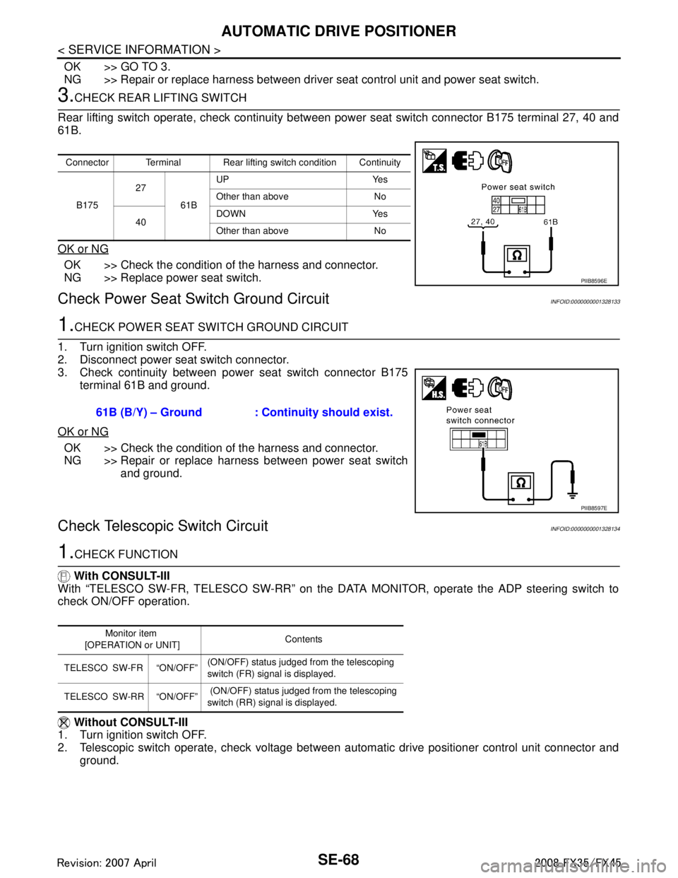
3.CHECK REAR LIFTING SWITCH
Rear lifting switch operate, check continuity betw een power seat switch connector B175 terminal 27, 40 and
61B.
OK or NG
OK >> Check the condition of the harness and connector.
NG >> Replace power seat switch.
Check Power Seat Switch Ground CircuitINFOID:0000000001328133
1.CHECK POWER SEAT SWITCH GROUND CIRCUIT
1. Turn ignition switch OFF.
2. Disconnect power seat switch connector.
3. Check continuity between power seat switch connector B175 terminal 61B and ground.
OK or NG
OK >> Check the condition of the harness and connector.
NG >> Repair or replace harness between power seat switch and ground.
Check Telescopic Switch CircuitINFOID:0000000001328134
1.CHECK FUNCTION
With CONSULT-III
With “TELESCO SW-FR, TELESCO SW-RR” on the DA TA MONITOR, operate the ADP steering switch to
check ON/OFF operation.
Without CONSULT-III
1. Turn ignition switch OFF.
2. Telescopic switch operate, check voltage between aut omatic drive positioner control unit connector and
ground.
Connector Terminal Rear lifting switch condition Continuity
B175 27
61BUP Yes
Other than above No
40 DOWN Yes
Other than above No
PIIB8596E
61B (B/Y) – Ground : Continuity should exist.
PIIB8597E
Monitor item
[OPERATION or UNIT] Contents
TELESCO SW-FR “ON/OFF” (ON/OFF) status judged from the telescoping
switch (FR) signal is displayed.
TELESCO SW-RR “ON/OFF” (ON/OFF) status judged from the telescoping
switch (RR) signal is displayed.
3AA93ABC3ACD3AC03ACA3AC03AC63AC53A913A773A893A873A873A8E3A773A983AC73AC93AC03AC3
3A893A873A873A8F3A773A9D3AAF3A8A3A8C3A863A9D3AAF3A8B3A8C
Page 3787 of 3924

TF-1
DRIVELINE/AXLE
CEF
G H
I
J
K L
M
SECTION TF
A
B
TF
N
O P
CONTENTS
TRANSFER
SERVICE INFORMATION .. ..........................3
DTC INDEX ..................................................... .....3
C1201-C1210, U1000 ......................................... ......3
PRECAUTIONS ...................................................4
Precaution for Supplemental Restraint System
(SRS) "AIR BAG" and "SEAT BELT PRE-TEN-
SIONER" ............................................................. ......
4
Precaution .................................................................4
Service Notice or Precaution .....................................5
PREPARATION ...................................................6
Special Service Tool ........................................... ......6
Commercial Service Tool ..........................................7
NOISE, VIBRATION AND HARSHNESS
(NVH) TROUBLESHOOTING .............................
9
NVH Troubleshooting Chart ................................ ......9
TRANSFER FLUID .............................................10
Replacement ....................................................... ....10
Inspection ................................................................10
AWD SYSTEM ................................................ ....11
Power Transfer Diagram ..................................... ....11
System Description .................................................11
Schematic ...............................................................13
CAN Communication ...............................................13
TROUBLE DIAGNOSIS .....................................14
Fail-Safe Function ............................................... ....14
How to Perform Trouble Diagnosis .........................14
Location of Electrical Parts ......................................15
Circuit Diagram .......................................................16
Wiring Diagram - AWD - ..........................................17
Trouble Diagnosis Chart by Symptom ....................20
AWD Control Unit Input/Output Signal Reference
Value ................................................................... ....
20
CONSULT-III Function (ALL MODE AWD/4WD) ....21
TROUBLE DIAGNOSIS FOR SYSTEM .............24
DTC C1201 CONTROLLER FAILURE ................ ....24
DTC C1203 ABS SYSTEM ......................................24
DTC C1204 4WD SOLENOID ............................. ....25
DTC C1205 4WD ACTUATOR RLY ........................27
DTC C1210 ENGINE SIGNAL 1 ..............................28
DTC U1000 CAN COMM CIRCUIT .........................28
Power Supply Circuit for AWD Control Unit .............28
TROUBLE DIAGNOSIS FOR SYMPTOMS ......30
AWD Warning Lamp Does Not Turn ON When the
Ignition Switch Is Turned to ON ...............................
30
AWD Warning Lamp Does Not Turn OFF Several
Seconds after Engine Started ..................................
30
Heavy Tight-Corner Braking Symptom Occurs
When the Vehicle Is Driven and the Steering
Wheel Is Turned Fully to Either Side after the En-
gine Is Started .........................................................
32
Vehicle Does Not Enter AWD Mode Even Though
AWD Warning Lamp Turned to OFF .......................
33
While Driving, AWD Warning Lamp Flashes Rap-
idly (When Flashing in Approx. 1 Minute and Then
Turning OFF) ....................................................... ....
33
While Driving, AWD Warning Lamp Flashes Slow-
ly (When Continuing to Flash until Turning Ignition
Switch OFF) .............................................................
33
AWD CONTROL UNIT ......................................35
Removal and Installation .........................................35
FRONT OIL SEAL .............................................36
Removal and Installation .........................................36
REAR OIL SEAL ...............................................37
Removal and Installation .........................................37
AIR BREATHER HOSE ....................................39
Removal and Installation .........................................39
TRANSFER ASSEMBLY ..................................40
Removal and Installation .........................................40
Disassembly and Assembly .....................................40
3AA93ABC3ACD3AC03ACA3AC03AC63AC53A913A773A893A873A873A8E3A773A983AC73AC93AC03AC3
3A893A873A873A8F3A773A9D3AAF3A8A3A8C3A863A9D3AAF3A8B3A8C
Page 3806 of 3924

TF-20
< SERVICE INFORMATION >
TROUBLE DIAGNOSIS
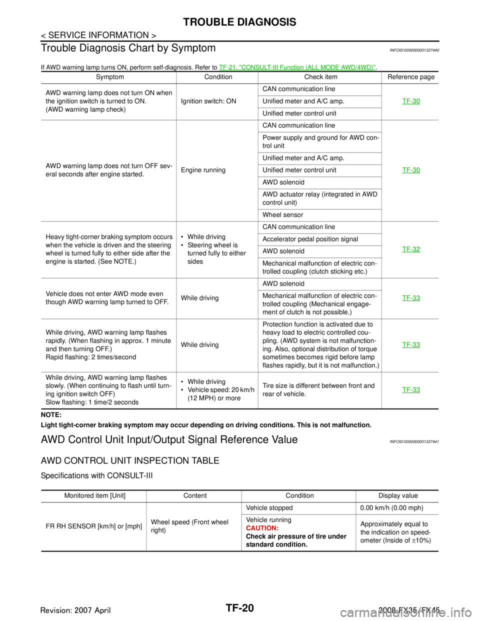
Trouble Diagnosis Chart by Symptom
INFOID:0000000001327440
If AWD warning lamp turns ON, perform self-diagnosis. Refer to TF-21, "CONSULT-III Function (ALL MODE AWD/4WD)".
NOTE:
Light tight-corner braking symptom may occur depending on driving conditions. This is not malfunction.
AWD Control Unit Input/Output Signal Reference ValueINFOID:0000000001327441
AWD CONTROL UNIT INSPECTION TABLE
Specifications with CONSULT-III
Symptom Condition Check item Reference page
AWD warning lamp does not turn ON when
the ignition switch is turned to ON.
(AWD warning lamp check) Ignition switch: ONCAN communication line
TF-30
Unified meter and A/C amp.
Unified meter control unit
AWD warning lamp does not turn OFF sev-
eral seconds after engine started. Engine runningCAN communication line
TF-30
Power supply and ground for AWD con-
trol unit
Unified meter and A/C amp.
Unified meter control unit
AWD solenoid
AWD actuator relay (integrated in AWD
control unit)
Wheel sensor
Heavy tight-corner braking symptom occurs
when the vehicle is driven and the steering
wheel is turned fully to either side after the
engine is started. (See NOTE.) While driving
Steering wheel is
turned fully to either
sides CAN communication line
TF-32
Accelerator pedal position signal
AWD solenoid
Mechanical malfunction of electric con-
trolled coupling (clutch sticking etc.)
Vehicle does not enter AWD mode even
though AWD warning lamp turned to OFF. While drivingAWD solenoid
TF-33
Mechanical malfunction of electric con-
trolled coupling (Mechanical engage-
ment of clutch is not possible.)
While driving, AWD warning lamp flashes
rapidly. (When flashing in approx. 1 minute
and then turning OFF.)
Rapid flashing: 2 times/second While drivingProtection function is activated due to
heavy load to electric controlled cou-
pling. (AWD system is not malfunction-
ing. Also, optional distribution of torque
sometimes becomes rigid before lamp
flashes rapidly, but it is not malfunction.) TF-33
While driving, AWD warning lamp flashes
slowly. (When continuing to flash until turn-
ing ignition switch OFF)
Slow flashing: 1 time/2 seconds While driving
Vehicle speed: 20 km/h
(12 MPH) or more Tire size is different between front and
rear of vehicle.
TF-33
Monitored item [Unit] Content Condition Display value
FR RH SENSOR [km/h] or [mph] Wheel speed (Front wheel
right)Vehicle stopped 0.00 km/h (0.00 mph)
Vehicle running
CAUTION:
Check air pressure of tire under
standard condition.
Approximately equal to
the indication on speed-
ometer (Inside of
±10%)
3AA93ABC3ACD3AC03ACA3AC03AC63AC53A913A773A893A873A873A8E3A773A983AC73AC93AC03AC3
3A893A873A873A8F3A773A9D3AAF3A8A3A8C3A863A9D3AAF3A8B3A8C