2008 INFINITI FX35 power steering
[x] Cancel search: power steeringPage 3636 of 3924
CHARGING SYSTEMSC-27
< SERVICE INFORMATION >
C
DE
F
G H
I
J
L
M A
B
SC
N
O P
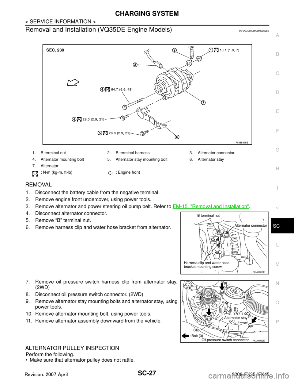
Removal and Installation (VQ35DE Engine Models)INFOID:0000000001328258
REMOVAL
1. Disconnect the battery cabl e from the negative terminal.
2. Remove engine front undercover, using power tools.
3. Remove alternator and power steering oil pump belt. Refer to EM-15, "
Removal and Installation".
4. Disconnect alternator connector.
5. Remove “B” terminal nut.
6. Remove harness clip and water hose bracket from alternator.
7. Remove oil pressure switch harness clip from alternator stay. (2WD)
8. Disconnect oil pressure switch connector. (2WD)
9. Remove alternator stay mounting bolts and alternator stay, using power tools.
10. Remove alternator mounting bolt, using power tools.
11. Remove alternator assembly downward from the vehicle.
ALTERNATOR PULLEY INSPECTION
Perform the following.
Make sure that alternator pulley does not rattle.
1. B terminal nut 2. B terminal harness 3. Alternator connector
4. Alternator mounting bolt 5. Alternator stay mounting bolt 6. Alternator stay
7. Alternator
: N·m (kg-m, ft-lb) : Engine front
PKIB8815E
PKIA2358E
PKIA1923E
3AA93ABC3ACD3AC03ACA3AC03AC63AC53A913A773A893A873A873A8E3A773A983AC73AC93AC03AC3
3A893A873A873A8F3A773A9D3AAF3A8A3A8C3A863A9D3AAF3A8B3A8C
Page 3640 of 3924
SE-1
BODY
C
DE
F
G H
J
K L
M
SECTION SE
A
B
SE
N
O P
CONTENTS
SEAT
SERVICE INFORMATION .. ..........................3
DTC INDEX ..................................................... .....3
U1000 .................................................................. ......3
B2112-B2128 ............................................................3
PRECAUTIONS ...................................................4
Precaution for Supplemental Restraint System
(SRS) "AIR BAG" and "SEAT BELT PRE-TEN-
SIONER" ............................................................. ......
4
Service Notice ...........................................................4
PREPARATION ...................................................5
Special Service Tool ........................................... ......5
Commercial Service Tool ..........................................5
SQUEAK AND RATTLE TROUBLE DIAG-
NOSES ................................................................
6
Work Flow ........................................................... ......6
Generic Squeak and Rattle Troubleshooting ............8
Diagnostic Worksheet .............................................10
AUTOMATIC DRIVE POSITIONER ...................12
System Description ............................................. ....12
Component Parts and Harness Connector Loca-
tion ..........................................................................
16
CAN Communication System Description ...............17
CAN Communication Unit .......................................17
Schematic ...............................................................18
Wiring Diagram - AUT/DP - .....................................20
Terminal and Reference Value for BCM .................32
Terminal and Reference Value for Automatic
Drive Positioner Control Unit ...................................
32
Terminal and Reference Value for Driver Seat
Control Unit .............................................................
34
Work Flow ...............................................................37
Preliminary Check ...................................................37
CONSULT-III Function (AUTO DRIVE POS.) .........40
Check CAN Communication System ......................42
Symptom Chart .......................................................43
Check Sliding Motor Circuit .....................................44
Check Reclining Motor Circuit ............................. ....45
Check Front Lifting Motor Circuit .............................46
Check Rear Lifting Motor Circuit ..............................47
Check Telescopic Motor Circuit ...............................48
Check Tilt Motor Circuit ...........................................49
Check Driver Side Mirror Motor Circuit ....................50
Check Passenger Side Mirror Motor Circuit ............52
Check Sliding Sensor Circuit ...................................53
Check Reclining Sensor Circuit ...............................54
Check Front Lifting Sensor Circuit ...........................55
Check Rear Lifting Sensor Circuit ...........................56
Check Telescopic Sensor Circuit .............................57
Check Tilt Sensor Circuit .........................................58
Check Driver Side Mirror Sensor Circuit ..................59
Check Passenger Side Mirror Sensor Circuit ..........60
Check Steering and Door Mirror Sensor Power
Supply and Ground Circuit .................................. ....
61
Check Front Door Switch (Driver Side) Circuit ........62
Check Sliding Switch Circuit ....................................63
Check Reclining Switch Circuit ................................64
Check Front Lifting Switch Circuit ............................66
Check Rear Lifting Switch Circuit ............................67
Check Power Seat Switch Ground Circuit ...............68
Check Telescopic Switch Circuit .............................68
Check Tilt Switch Circuit ..........................................70
Check Door Mirror Remote Control Switch
(Changeover Switch) Circuit ................................ ....
71
Check Door Mirror Remote Control Switch (Mirror
Switch) Circuit ...................................................... ....
73
Check A/T Device (Park Position Switch) Circuit ....74
Check Key Switch Circuit (With Intelligent Key) ......76
Check Key Switch Circuit (Without Intelligent Key) ....77
Check Seat Memory Switch Circuit ..................... ....78
Check Seat Memory Indicator Lamp Circuit ............79
Check UART Communication Line Circuit ...............80
Check Lumbar Support Circuit ............................ ....82
POWER SEAT ...................................................84
Wiring Diagram - SEAT - .........................................84
HEATED SEAT .................................................86
3AA93ABC3ACD3AC03ACA3AC03AC63AC53A913A773A893A873A873A8E3A773A983AC73AC93AC03AC3
3A893A873A873A8F3A773A9D3AAF3A8A3A8C3A863A9D3AAF3A8B3A8C
Page 3651 of 3924

SE-12
< SERVICE INFORMATION >
AUTOMATIC DRIVE POSITIONER
AUTOMATIC DRIVE POSITIONER
System DescriptionINFOID:0000000001328097
The system automatically moves the driver seat to facilitate entry/exit to/from the vehicle. The automatic
drive positioner control unit can also store the optimum driving positions (driver seat, steering wheel position
(tilt, telescopic) and door mirror position) for 2 people. If the driver is changes, one-touch operation allows
changing to the other driving position.
The settings (ON/OFF) of the automatic sliding s eat (Entry/Exiting operation) at entry/exit can be changed
as desired, using the display unit in the center of the instrument panel. The set content is transmitted by
CAN communication, from display contro l unit to driver seat control unit.
Using CONSULT-III, the seat slide and steering wheel amount at entry/exit setting can be changed.
MANUAL OPERATION
The driving position [seat position, steering wheel posit ion (tilt, telescopic) and door mirror position] can be
adjusted with the power seat switch or ADP steering switch or door mirror remote control switch.
NOTE:
The seat can be manually operated with the ignition switch OFF.
The door mirrors can be manually operated with the ignition switch turned ACC or ON.
AUTOMATIC OPERATION
NOTE:
Disconnecting the battery erases the stored memory.
After connecting the battery, insert the key into the ignition cylinder and turn the driver door switch ON (open) →OFF (close) →ON
(open), the Entry/ Exiting operation becomes possible.
After exiting operation is carried out, return operation can be operated.
NOTE:
During automatic operation, if the ignition switch is turned ON →START, the automatic operation is suspended. When the ignition switch
returns to ON, it resumes.
MEMORY STORING AND KEYFOB INTERLOCK STORING
Store the 2 driving positions and shifts to t he stored driving position with the memory switch.
Function Description
Memory switch operation The seat, steering and door mirror move to the stored driving position by pushing
memory switch (1 or 2).
Entry/Exiting function Exiting operation At exit, the seat moves backward and steering wheel moves forward/upward.
Entry operation
At entry, the seat and steering wheel returns from the exiting position to the previous
driving position.
keyfob interlock operation Perform memory operation, exiting operation and entry operation by pressing keyfob
unlock button.
Auto operation temporary stop
conditions. When ignition switch turned to START during memory switch operation and return opera-
tion, memory switch operation and entry operation is stopped.
Auto operation stop conditions. When the vehicle speed becomes 7 km/h (4 MPH) or higher.
When the setting switch, memory switch 1, or 2 are pressed.
When A/T selector lever is in any position other than P.
When the door mirror remote control switch is operated (when ignition switch turned to
ON or ACC).
When power seat switch turned ON.
When ADP steering switch turned ON (telescopic operation or tilt operation).
When door mirror operates (only memory switch operation).
When driver seat sliding Entry/Exiting setting is OFF (only entry/exiting operation).
When steering wheel tilt and telescopic Entry/Exiting setting is OFF (only entry/exiting op-
eration).
When the tilt and telescopic sensor malfunction is detected.
3AA93ABC3ACD3AC03ACA3AC03AC63AC53A913A773A893A873A873A8E3A773A983AC73AC93AC03AC3
3A893A873A873A8F3A773A9D3AAF3A8A3A8C3A863A9D3AAF3A8B3A8C
Page 3656 of 3924
AUTOMATIC DRIVE POSITIONERSE-17
< SERVICE INFORMATION >
C
DE
F
G H
J
K L
M A
B
SE
N
O P
CAN Communication System DescriptionINFOID:0000000001328099
CAN (Controller Area Network) is a serial communication li ne for real time application. It is an on-vehicle mul-
tiplex communication line with high data communication speed and excellent error detection ability. Many elec-
tronic control units are equipped onto a vehicle, and each control unit shares information and links with other
control units during operation (not independent). In CAN communication, control units are connected with 2
communication lines (CAN H line, CAN L line) allowing a high rate of information transmission with less wiring.
Each control unit transmits/receives data but selectively reads required data only.
CAN Communication UnitINFOID:0000000001328100
Refer to LAN-43, "CAN System Specification Chart".
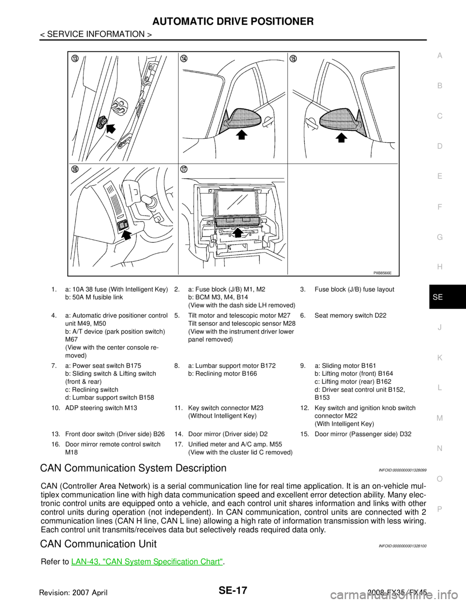
1. a: 10A 38 fuse (With Intelligent Key)
b: 50A M fusible link 2. a: Fuse block (J/B) M1, M2
b: BCM M3, M4, B14
(View with the dash side LH removed) 3. Fuse block (J/B) fuse layout
4. a: Automatic drive positioner control unit M49, M50
b: A/T device (park position switch)
M67
(View with the center console re-
moved) 5. Tilt motor and telescopic motor M27
Tilt sensor and telescopic sensor M28
(View with the instrument driver lower
panel removed) 6. Seat memory switch D22
7. a: Power seat switch B175 b: Sliding switch & Lifting switch
(front & rear)
c: Reclining switch
d: Lumbar support switch B158 8. a: Lumbar support motor B172
b: Reclining motor B166 9. a: Sliding motor B161
b: Lifting motor (front) B164
c: Lifting motor (rear) B162
d: Driver seat control unit B152,
B153
10. ADP steering switch M13 11. Key switch connector M23 (Without Intelligent Key)12. Key switch and ignition knob switch
connector M22
(With Intelligent Key)
13. Front door switch (Driver side) B26 14. Door mirro r (Driver side) D2 15. Door mirror (Passenger side) D32
16. Door mirror remote control switch M18 17. Unified meter and A/C amp. M55
(View with the clus ter lid C removed)
PIIB8566E
3AA93ABC3ACD3AC03ACA3AC03AC63AC53A913A773A893A873A873A8E3A773A983AC73AC93AC03AC3
3A893A873A873A8F3A773A9D3AAF3A8A3A8C3A863A9D3AAF3A8B3A8C
Page 3677 of 3924
SE-38
< SERVICE INFORMATION >
AUTOMATIC DRIVE POSITIONER
NOTE:
After the setting is registered, the new setting is effective, even if the battery is disconnected.
CHECK POWER SUPPLY AND GROUND
1.CHECK FUSE
Check if any of the following fuses in the BCM are blown.
Check 50A fusible link (letter M, located in the fuse and fusible link box.)
Check 15A fuse [No.22, located in the fuse block (J/B)]
Check 10A fuse [No.1, located in the fuse block (J/B)]
Check 10A fuse [No.6, located in the fuse block (J/B)]
NOTE:
Refer to SE-16, "
Component Parts and Harness Connector Location".
OK or NG
OK >> GO TO 2.
NG >> If fuse is blown out, be sure to eliminate cause of malfunction before installing new fuse. Refer to SE-16, "
Component Parts and Harness Connector Location".
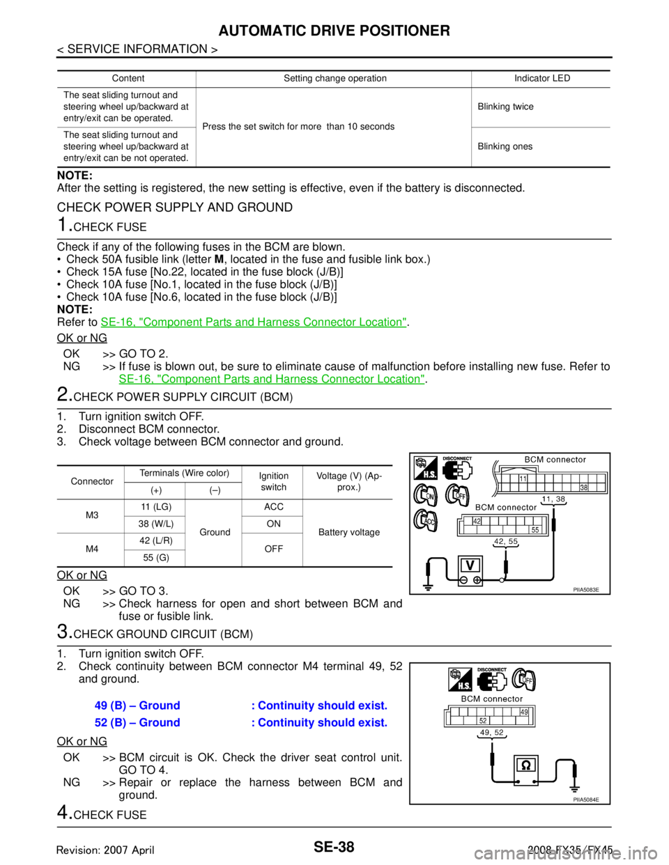
2.CHECK POWER SUPPLY CIRCUIT (BCM)
1. Turn ignition switch OFF.
2. Disconnect BCM connector.
3. Check voltage between BCM connector and ground.
OK or NG
OK >> GO TO 3.
NG >> Check harness for open and short between BCM and fuse or fusible link.
3.CHECK GROUND CIRCUIT (BCM)
1. Turn ignition switch OFF.
2. Check continuity between BCM connector M4 terminal 49, 52 and ground.
OK or NG
OK >> BCM circuit is OK. Check the driver seat control unit. GO TO 4.
NG >> Repair or replace the harness between BCM and ground.
4.CHECK FUSE
Content Setting change operation Indicator LED
The seat sliding turnout and
steering wheel up/backward at
entry/exit can be operated. Press the set switch for more than 10 seconds Blinking twice
The seat sliding turnout and
steering wheel up/backward at
entry/exit can be not operated. Blinking ones
Connector
Terminals (Wire color)
Ignition
switch Voltage (V) (Ap-
prox.)
(+) (–)
M3 11 ( L G )
Ground ACC
Battery voltage
38 (W/L) ON
M4 42 (L/R)
OFF
55 (G)
PIIA5083E
49 (B) – Ground : Continuity should exist.
52 (B) – Ground : Continuity should exist.
PIIA5084E
3AA93ABC3ACD3AC03ACA3AC03AC63AC53A913A773A893A873A873A8E3A773A983AC73AC93AC03AC3
3A893A873A873A8F3A773A9D3AAF3A8A3A8C3A863A9D3AAF3A8B3A8C
Page 3682 of 3924
AUTOMATIC DRIVE POSITIONERSE-43
< SERVICE INFORMATION >
C
DE
F
G H
J
K L
M A
B
SE
N
O P
Is “CAN COMM CIRCUIT” displayed?
YES >> Refer to LAN-14, "Trouble Diagnosis Flow Chart".
NO >> INSPECTION END.
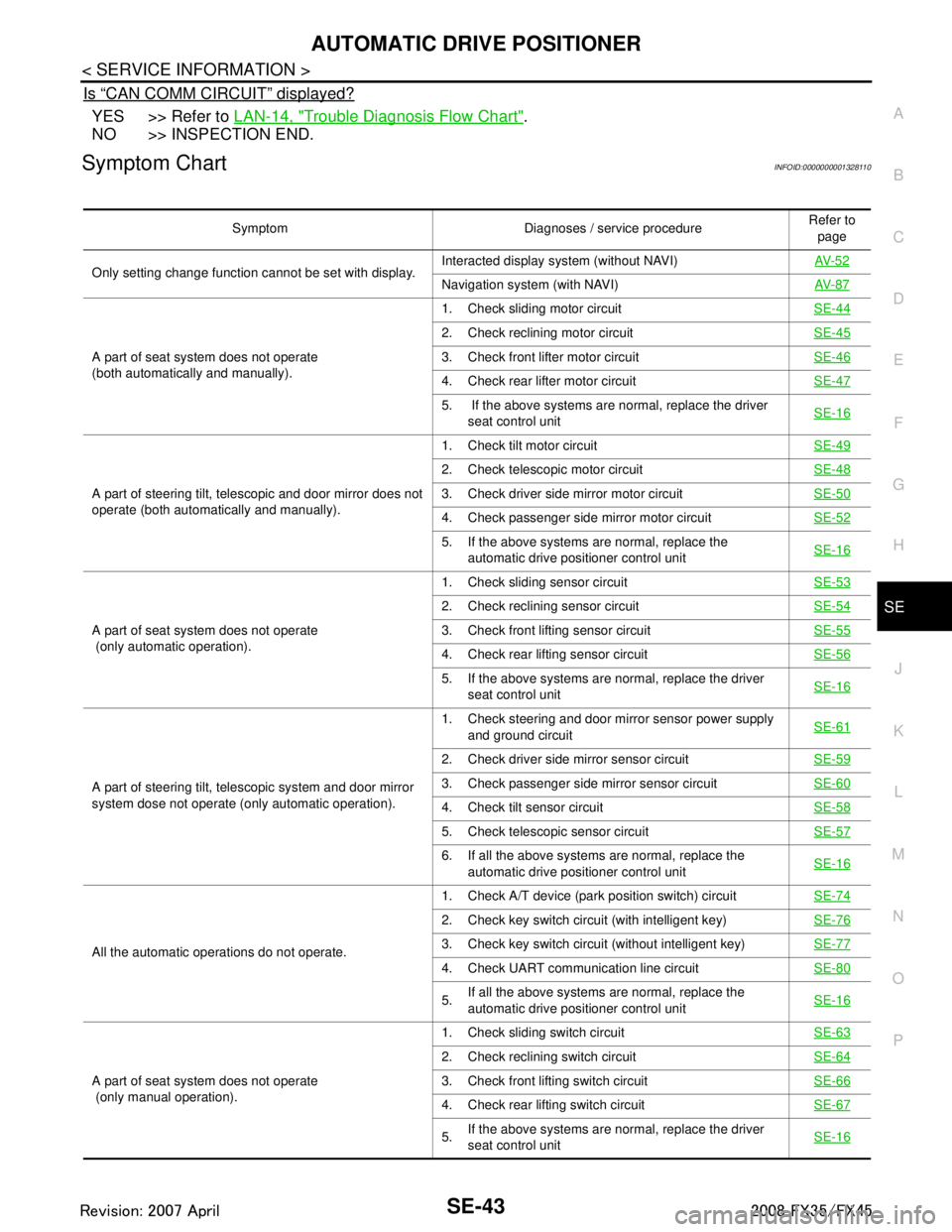
Symptom ChartINFOID:0000000001328110
Symptom Diagnoses / service procedure Refer to
page
Only setting change function cannot be set with display. Interacted display system (without NAVI)
AV- 5 2
Navigation system (with NAVI)AV- 8 7
A part of seat system does not operate
(both automatically and manually).1. Check sliding motor circuit
SE-44
2. Check reclining motor circuit SE-45
3. Check front lifter motor circuitSE-46
4. Check rear lifter motor circuitSE-47
5. If the above systems are normal, replace the driver
seat control unit SE-16
A part of steering tilt, telescopic and door mirror does not
operate (both automatically and manually). 1. Check tilt motor circuit
SE-49
2. Check telescopic motor circuitSE-48
3. Check driver side mirror motor circuit SE-50
4. Check passenger side mirror motor circuit SE-52
5. If the above systems are normal, replace the
automatic drive positioner control unit SE-16
A part of seat system does not operate
(only automatic operation). 1. Check sliding sensor circuit
SE-53
2. Check reclining sensor circuitSE-54
3. Check front lifting sensor circuitSE-55
4. Check rear lifting sensor circuitSE-56
5. If the above systems are normal, replace the driver
seat control unit SE-16
A part of steering tilt, telescopic system and door mirror
system dose not operate (only automatic operation). 1. Check steering and door mirror sensor power supply
and ground circuit SE-61
2. Check driver side mirror sensor circuit
SE-59
3. Check passenger side mirror sensor circuitSE-60
4. Check tilt sensor circuitSE-58
5. Check telescopic sensor circuitSE-57
6. If all the above systems are normal, replace the
automatic drive positioner control unit SE-16
All the automatic operations do not operate. 1. Check A/T device (park position switch) circuit
SE-74
2. Check key switch circuit (with intelligent key)SE-76
3. Check key switch circuit (without intelligent key)SE-77
4. Check UART communication line circuitSE-80
5.If all the above systems are normal, replace the
automatic drive positioner control unit
SE-16
A part of seat system does not operate
(only manual operation). 1. Check sliding switch circuit
SE-63
2. Check reclining switch circuitSE-64
3. Check front lifting switch circuitSE-66
4. Check rear lifting switch circuitSE-67
5.If the above systems are normal, replace the driver
seat control unit SE-16
3AA93ABC3ACD3AC03ACA3AC03AC63AC53A913A773A893A873A873A8E3A773A983AC73AC93AC03AC3
3A893A873A873A8F3A773A9D3AAF3A8A3A8C3A863A9D3AAF3A8B3A8C
Page 3683 of 3924
SE-44
< SERVICE INFORMATION >
AUTOMATIC DRIVE POSITIONER
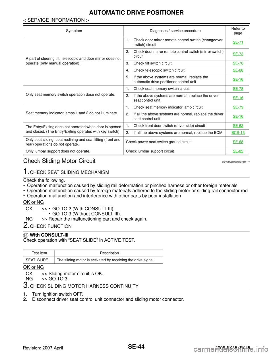
Check Sliding Motor Circuit
INFOID:0000000001328111
1.CHECK SEAT SLIDING MECHANISM
Check the following.
Operation malfunction caused by sliding rail deformation or pinched harness or other foreign materials
Operation malfunction caused by foreign materials adhered to the sliding motor or sliding rail connector rod
Operation malfunction and interference wit h other parts by poor installation
OK or NG
OK >> GO TO 2 (With CONSULT-III). GO TO 3 (Without CONSULT-III).
NG >> Repair the malfunctioning part and check again.
2.CHECK FUNCTION
With CONSULT-III
Check operation with “SEAT SLIDE” in ACTIVE TEST.
OK or NG
OK >> Sliding motor circuit is OK.
NG >> GO TO 3.
3.CHECK SLIDING MOTOR HARNESS CONTINUITY
1. Turn ignition switch OFF.
2. Disconnect driver seat control unit connector and sliding motor connector.
A part of steering tilt, telescopic and door mirror does not
operate (only manual operation). 1. Check door mirror remote
control switch (changeover
switch) circuit SE-71
2. Check door mirror remote co
ntrol switch (mirror switch)
circuit SE-73
3. Check tilt switch circuit
SE-70
4. Check telescopic switch circuitSE-68
5. If the above systems are normal, replace the
automatic drive positioner control unit SE-16
Only seat memory switch operation dose not operate. 1. Check seat memory switch circuit
SE-782. If the above systems are normal, replace the driver
seat control unit SE-16
Seat memory indicator lamps 1 and 2 do not illuminate. 1. Check seat memory indicator lamp circuit
SE-792. If all the above systems are normal, replace the driver
seat control unit SE-16
The Entry/Exiting does not operated when door is opened
and closed. (The Entry/Exiting operates with key switch) 1. Check front door switch
(driver side) circuit SE-62
2. If all the above systems are normal, replace the BCM BCS-13
Only seat sliding, seat reclining and seat lifting (front and
rear) operations do not operate.Check power seat switch ground circuit
SE-68
Only lumbar support does not operate. Check lumbar support circuit SE-82
Symptom Diagnoses / service procedureRefer to
page
Test item Description
SEAT SLIDE The sliding motor is activated by receiving the drive signal.
3AA93ABC3ACD3AC03ACA3AC03AC63AC53A913A773A893A873A873A8E3A773A983AC73AC93AC03AC3
3A893A873A873A8F3A773A9D3AAF3A8A3A8C3A863A9D3AAF3A8B3A8C
Page 3700 of 3924
AUTOMATIC DRIVE POSITIONERSE-61
< SERVICE INFORMATION >
C
DE
F
G H
J
K L
M A
B
SE
N
O P
NG >> GO TO 3.
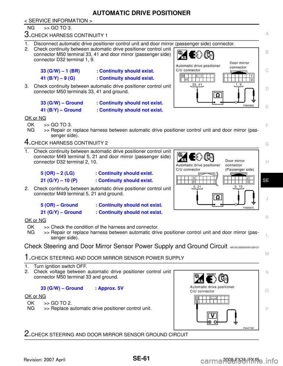
3.CHECK HARNESS CONTINUITY 1
1. Disconnect automatic drive positioner contro l unit and door mirror (passenger side) connector.
2. Check continuity between automat ic drive positioner control unit
connector M50 terminal 33, 41 and door mirror (passenger side)
connector D32 terminal 1, 9.
3. Check continuity between automat ic drive positioner control unit
connector M50 terminals 33, 41 and ground.
OK or NG
OK >> GO TO 3.
NG >> Repair or replace harness between automatic drive positioner control unit and door mirror (pas-
senger side).
4.CHECK HARNESS CONTINUITY 2
1. Check continuity between automat ic drive positioner control unit
connector M49 terminal 5, 21 and door mirror (passenger side)
connector D32 terminal 2, 10.
2. Check continuity between automat ic drive positioner control unit
connector M49 terminal 5, 21 and ground.
OK or NG
OK >> Check the condition of the harness and connector.
NG >> Repair or replace harness between automatic drive positioner control unit and door mirror (pas-
senger side).
Check Steering and Door Mirror Sensor Power Supp ly and Ground CircuitINFOID:0000000001328127
1.CHECK STEERING AND DOOR MIRROR SENSOR POWER SUPPLY
1. Turn ignition switch OFF.
2. Check voltage between automatic drive positioner control unit
connector M50 terminal 33 and ground.
OK or NG
OK >> GO TO 2.
NG >> Replace automatic drive positioner control unit.
2.CHECK STEERING AND DOOR MIRROR SENSOR GROUND CIRCUIT
33 (G/W) – 1 (BR) : Continuity should exist.
41 (B/Y) – 9 (G) : Continuity should exist.
33 (G/W) – Ground : Continuity should not exist.
41 (B/Y) – Ground : Continuity should not exist.
PIIB8586E
5 (OR) – 2 (LG) : Continuity should exist.
21 (G/Y) – 10 (P) : Cont
inuity should exist.
5 (OR) – Ground : Continuity should not exist.
21 (G/Y) – Ground : Contin uity should not exist.
PIIB8587E
33 (G/W) – Ground : Approx. 5V
PIIA4778E
3AA93ABC3ACD3AC03ACA3AC03AC63AC53A913A773A893A873A873A8E3A773A983AC73AC93AC03AC3
3A893A873A873A8F3A773A9D3AAF3A8A3A8C3A863A9D3AAF3A8B3A8C