2008 INFINITI FX35 fuse
[x] Cancel search: fusePage 3719 of 3924
SE-80
< SERVICE INFORMATION >
AUTOMATIC DRIVE POSITIONER
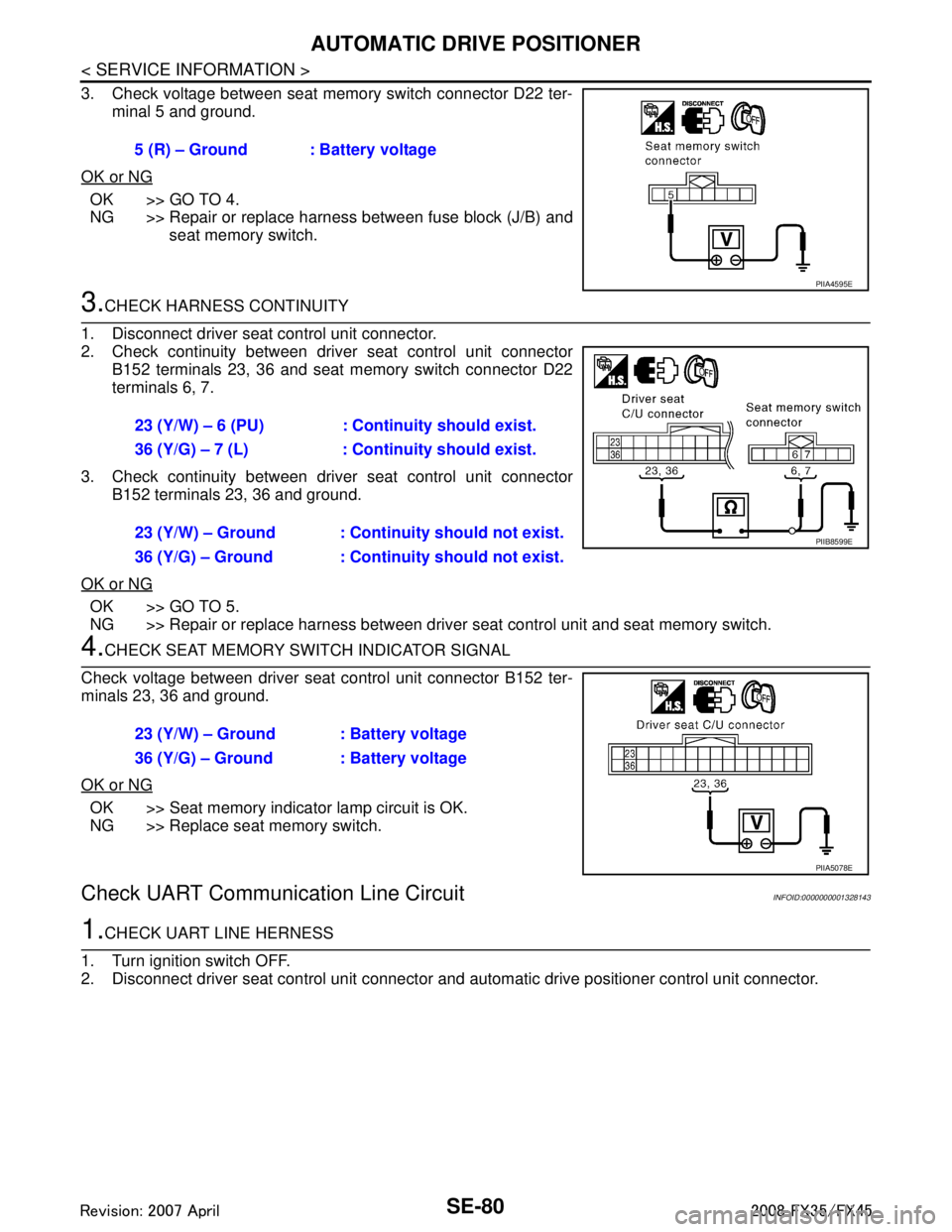
3. Check voltage between seat memory switch connector D22 ter-minal 5 and ground.
OK or NG
OK >> GO TO 4.
NG >> Repair or replace harness between fuse block (J/B) and seat memory switch.
3.CHECK HARNESS CONTINUITY
1. Disconnect driver seat control unit connector.
2. Check continuity between driv er seat control unit connector
B152 terminals 23, 36 and seat memory switch connector D22
terminals 6, 7.
3. Check continuity between driv er seat control unit connector
B152 terminals 23, 36 and ground.
OK or NG
OK >> GO TO 5.
NG >> Repair or replace harness between driver seat control unit and seat memory switch.
4.CHECK SEAT MEMORY SWITCH INDICATOR SIGNAL
Check voltage between driver seat control unit connector B152 ter-
minals 23, 36 and ground.
OK or NG
OK >> Seat memory indicator lamp circuit is OK.
NG >> Replace seat memory switch.
Check UART Communication Line CircuitINFOID:0000000001328143
1.CHECK UART LINE HERNESS
1. Turn ignition switch OFF.
2. Disconnect driver seat control unit connector and automatic drive positioner control unit connector.
5 (R) – Ground : Battery voltage
PIIA4595E
23 (Y/W) – 6 (PU) : Continuity should exist.
36 (Y/G) – 7 (L) : Continuity should exist.
23 (Y/W) – Ground : Continuity should not exist.
36 (Y/G) – Ground : Continuity should not exist.
PIIB8599E
23 (Y/W) – Ground : Battery voltage
36 (Y/G) – Ground : Battery voltage
PIIA5078E
3AA93ABC3ACD3AC03ACA3AC03AC63AC53A913A773A893A873A873A8E3A773A983AC73AC93AC03AC3
3A893A873A873A8F3A773A9D3AAF3A8A3A8C3A863A9D3AAF3A8B3A8C
Page 3721 of 3924
SE-82
< SERVICE INFORMATION >
AUTOMATIC DRIVE POSITIONER
When voltage signal dose not appear with a constant voltage (approx. 5V), replace automatic
driver seat control unit.
When voltage signal dose not appear with a constant voltage (approx. 0V), replace driver seat
control unit.
4.CHECK DRIVER SEAT CONTROL UNIT
Dose the automatic drive positioner operate, when the driver seat control unit exchanged?
Does seat memory function operate?
YES >> Replace automatic drive positioner control unit.
NG >> Replace driver seat control unit.
Check Lumbar Support CircuitINFOID:0000000001328144
1.CHECK LUMBAR SUPPORT SWITCH
1. Turn ignition switch OFF.
2. Disconnect lumbar support switch connector.
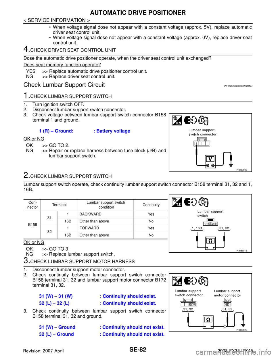
3. Check voltage between lumbar support switch connector B158 terminal 1 and ground.
OK or NG
OK >> GO TO 2.
NG >> Repair or replace harness between fuse block (J/B) and lumbar support switch.
2.CHECK LUMBAR SUPPORT SWITCH
Lumbar support switch operate, check continuity lum bar support switch connector B158 terminal 31, 32 and 1,
16B.
OK or NG
OK >> GO TO 3.
NG >> Replace lumbar support switch.
3.CHECK LUMBAR SUPPORT MOTOR HARNESS
1. Disconnect lumbar support motor connector.
2. Check continuity between lumbar support switch connector B158 terminal 31, 32 and lumbar support motor connector B172
terminal 31, 32.
3. Check continuity between lumbar support switch connector B158 terminal 31, 32 and ground.1 (R) – Ground: : Battery voltage
PIIB8600E
Con-
nector Te r m i n a l
Lumbar support switch
condition Continuity
B158 31
1 BACKWARD Yes
16B Other than above No
32 1FORWARD Yes
16B Other than above No
PIIB8601E
31 (W) − 31 (W) : Continuity should exist.
32 (L) − 32 (L) : Continuity should exist.
31 (W) − Ground : Continuity should not exist.
32 (L) − Ground : Continuity should not exist.
PIIB8602E
3AA93ABC3ACD3AC03ACA3AC03AC63AC53A913A773A893A873A873A8E3A773A983AC73AC93AC03AC3
3A893A873A873A8F3A773A9D3AAF3A8A3A8C3A863A9D3AAF3A8B3A8C
Page 3729 of 3924
SE-90
< SERVICE INFORMATION >
FRONT SEAT
REMOVAL
When removing or installing the seat trim, carefully handle it to keep dirt out and avoid damage.
CAUTION:
Before removing the front seat, turn ignition switch OFF, disconnect both battery cables and wait at
least 3 minutes.
When checking the power seat circuit for continuity using a circuit tester, do not confuse its connec-
tor with the side air bag modul e connector. Such an error may cause the air bag to deploy.
Do not drop, tilt, or bump the side air bag module installing in the seat. Always handle it with care.
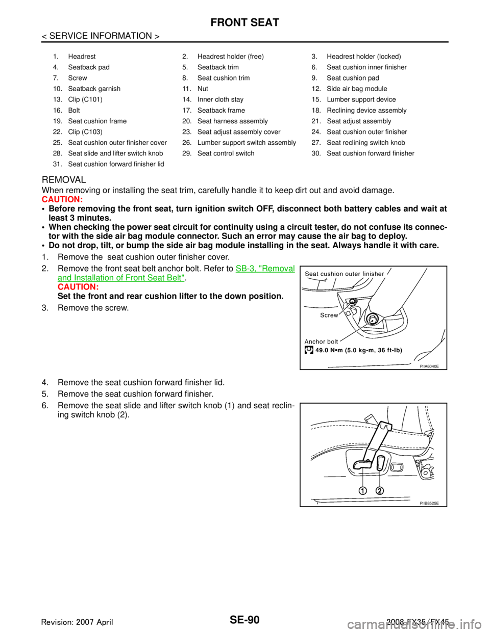
1. Remove the seat cushion outer finisher cover.
2. Remove the front seat belt anchor bolt. Refer to SB-3, "
Removal
and Installation of Front Seat Belt".
CAUTION:
Set the front and rear cushion lifter to the down position.
3. Remove the screw.
4. Remove the seat cushion forward finisher lid.
5. Remove the seat cushion forward finisher.
6. Remove the seat slide and lifter switch knob (1) and seat reclin- ing switch knob (2).
1. Headrest 2. Headrest holder (free) 3. Headrest holder (locked)
4. Seatback pad 5. Seatback trim 6. Seat cushion inner finisher
7. Screw 8. Seat cushion trim 9. Seat cushion pad
10. Seatback garnish 11. Nut 12. Side air bag module
13. Clip (C101) 14. Inner cloth stay 15. Lumber support device
16. Bolt 17. Seatback frame 18. Reclining device assembly
19. Seat cushion frame 20. Seat harness assembly 21. Seat adjust assembly
22. Clip (C103) 23. Seat adjust assembly cover 24. Seat cushion outer finisher
25. Seat cushion outer finisher cover 26. Lumber support switch assembly 27. Seat reclining switch knob
28. Seat slide and lifter switch knob 29. Seat control switch 30. Seat cushion forward finisher
31. Seat cushion forward finisher lid
PIIA6040E
PIIB8525E
3AA93ABC3ACD3AC03ACA3AC03AC63AC53A913A773A893A873A873A8E3A773A983AC73AC93AC03AC3
3A893A873A873A8F3A773A9D3AAF3A8A3A8C3A863A9D3AAF3A8B3A8C
Page 3749 of 3924

SRS-12
< SERVICE INFORMATION >
TROUBLE DIAGNOSIS
TROUBLE DIAGNOSIS
Trouble Diagnosis IntroductionINFOID:0000000001524161
CAUTION:
Do not use electrical test equipment on any circuit related to the SRS unless instructed in this Ser-
vice Manual. SRS wiring harnesses can be identifi ed by yellow and/or orange harnesses or harness
connectors.
Do not repair, splice or modify the SRS wiring harn ess. If the harness is damaged, replace it with a
new one.
Keep ground portion clean.
DIAGNOSIS FUNCTION
The SRS self-diagnostic results can be read by us ing “AIR BAG” warning lamp and/or CONSULT-III.
The User mode is exclusively prepared for the customer (driver). This mode warns the driver of a system mal-
function through the operation of the “AIR BAG” warning lamp.
The Diagnosis mode allows the technician to locate and inspect the malfunctioning part.
The mode applications for the “AIR BAG” wa rning lamp and CONSULT-III are as follows:
HOW TO PERFORM TROUBLE DIAGNOSIS FOR QUICK AND ACCURATE REPAIR
A good understanding of the malfunction conditions can make troubleshooting faster and more accurate.
In general, each customer feels differently about a malf unction. It is important to fully understand the symp-
toms or conditions for a customer complaint.
Information from Customer
WHAT..... Vehicle model
WHEN..... Date, Frequencies
WHERE..... Road conditions
HOW..... Operating conditions, Symptoms
Preliminary Check
Make sure the following parts are in good order.
Battery (Refer to SC-4, "
How to Handle Battery".)
Fuse (Refer to SRS-16, "
Wiring Diagram - SRS -".)
System component-to-harness connections
Work Flow
OVERALL SEQUENCE
User mode Diagnosis mode Display type
“AIR BAG” warning lamp X X ON-OFF operation CONSULT-III — X Monitoring
3AA93ABC3ACD3AC03ACA3AC03AC63AC53A913A773A893A873A873A8E3A773A983AC73AC93AC03AC3
3A893A873A873A8F3A773A9D3AAF3A8A3A8C3A863A9D3AAF3A8B3A8C
Page 3750 of 3924
TROUBLE DIAGNOSISSRS-13
< SERVICE INFORMATION >
C
DE
F
G
I
J
K L
M A
B
SRS
N
O P
DETAILED FLOW
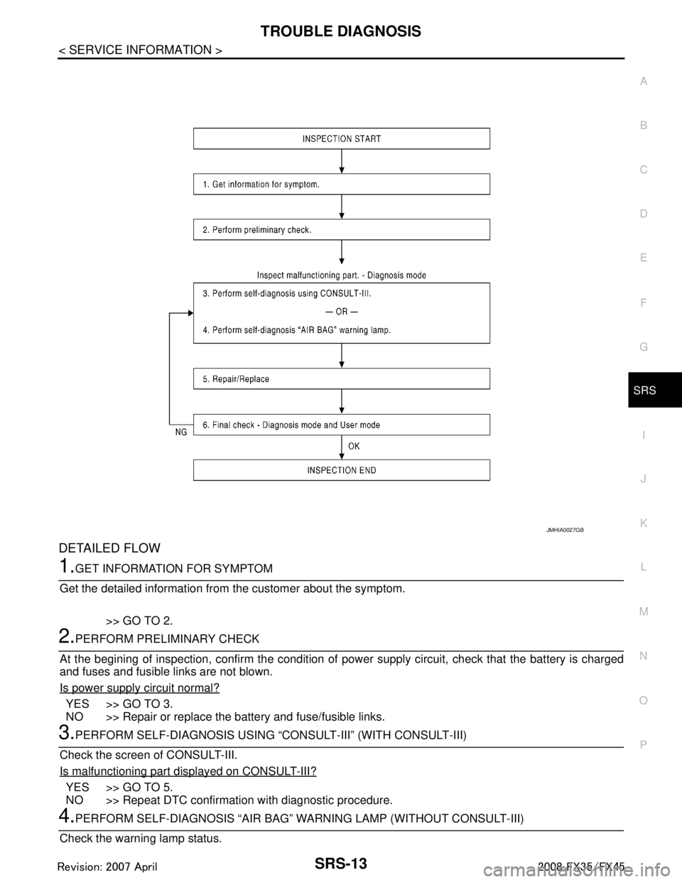
1.GET INFORMATION FOR SYMPTOM
Get the detailed information from the customer about the symptom.
>> GO TO 2.
2.PERFORM PRELIMINARY CHECK
At the begining of inspection, confirm the condition of pow er supply circuit, check that the battery is charged
and fuses and fusible links are not blown.
Is power supply circuit normal?
YES >> GO TO 3.
NO >> Repair or replace the battery and fuse/fusible links.
3.PERFORM SELF-DIAGNOSIS USING “C ONSULT-III” (WITH CONSULT-III)
Check the screen of CONSULT-III.
Is malfunctioning part displayed on CONSULT-III?
YES >> GO TO 5.
NO >> Repeat DTC confirmation with diagnostic procedure.
4.PERFORM SELF-DIAGNOSIS “AIR BAG” WA RNING LAMP (WITHOUT CONSULT-III)
Check the warning lamp status.
JMHIA0027GB
3AA93ABC3ACD3AC03ACA3AC03AC63AC53A913A773A893A873A873A8E3A773A983AC73AC93AC03AC3
3A893A873A873A8F3A773A9D3AAF3A8A3A8C3A863A9D3AAF3A8B3A8C
Page 3769 of 3924
SRS-32
< SERVICE INFORMATION >
TROUBLE DIAGNOSIS
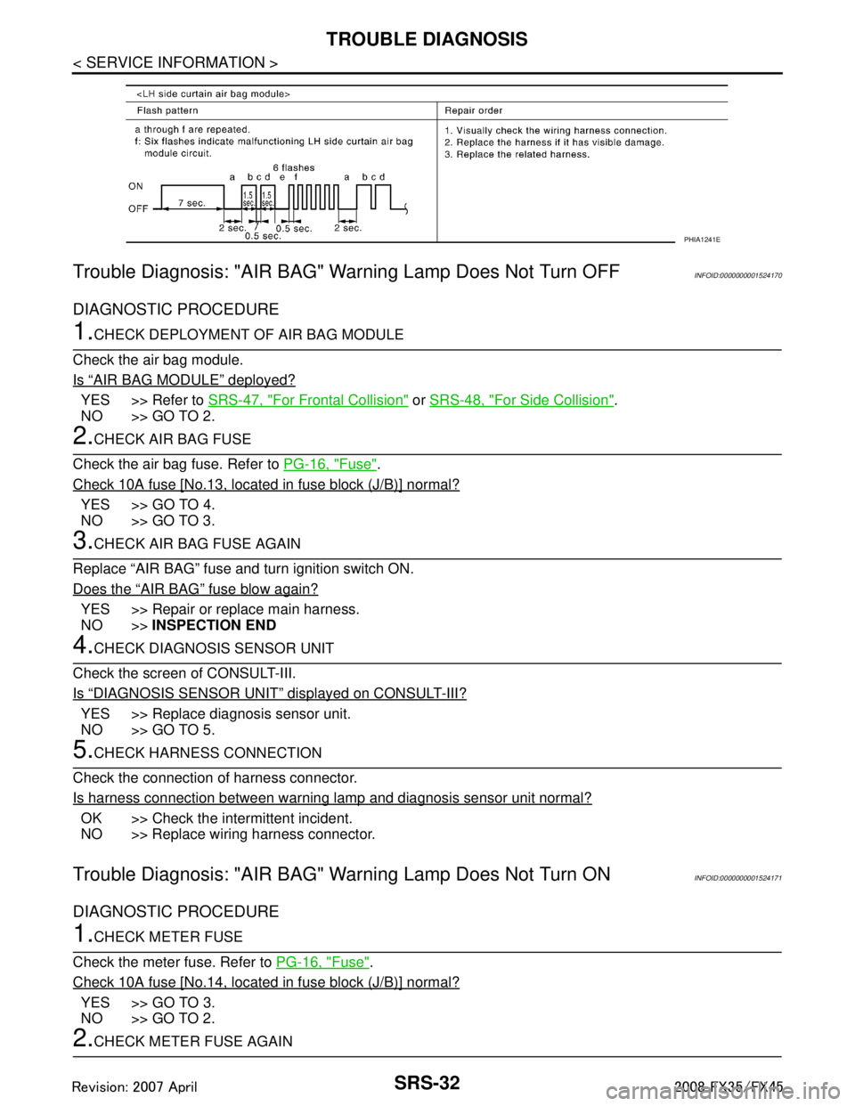
Trouble Diagnosis: "AIR BAG" Warning Lamp Does Not Turn OFF
INFOID:0000000001524170
DIAGNOSTIC PROCEDURE
1.CHECK DEPLOYMENT OF AIR BAG MODULE
Check the air bag module.
Is
“AIR BAG MODULE” deployed?
YES >> Refer to SRS-47, "For Frontal Collision" or SRS-48, "For Side Collision".
NO >> GO TO 2.
2.CHECK AIR BAG FUSE
Check the air bag fuse. Refer to PG-16, "
Fuse".
Check 10A fuse [No.13, located in fuse block (J/B)] normal?
YES >> GO TO 4.
NO >> GO TO 3.
3.CHECK AIR BAG FUSE AGAIN
Replace “AIR BAG” fuse and turn ignition switch ON.
Does the
“AIR BAG” fuse blow again?
YES >> Repair or replace main harness.
NO >> INSPECTION END
4.CHECK DIAGNOSIS SENSOR UNIT
Check the screen of CONSULT-III.
Is
“DIAGNOSIS SENSOR UNIT” displayed on CONSULT-III?
YES >> Replace diagnosis sensor unit.
NO >> GO TO 5.
5.CHECK HARNESS CONNECTION
Check the connection of harness connector.
Is harness connection between warning lamp and diagnosis sensor unit normal?
OK >> Check the intermittent incident.
NO >> Replace wiring harness connector.
Trouble Diagnosis: "AIR BAG" Warning Lamp Does Not Turn ONINFOID:0000000001524171
DIAGNOSTIC PROCEDURE
1.CHECK METER FUSE
Check the meter fuse. Refer to PG-16, "
Fuse".
Check 10A fuse [No.14, located in fuse block (J/B)] normal?
YES >> GO TO 3.
NO >> GO TO 2.
2.CHECK METER FUSE AGAIN
PHIA1241E
3AA93ABC3ACD3AC03ACA3AC03AC63AC53A913A773A893A873A873A8E3A773A983AC73AC93AC03AC3
3A893A873A873A8F3A773A9D3AAF3A8A3A8C3A863A9D3AAF3A8B3A8C
Page 3770 of 3924
![INFINITI FX35 2008 Service Manual
TROUBLE DIAGNOSISSRS-33
< SERVICE INFORMATION >
C
DE
F
G
I
J
K L
M A
B
SRS
N
O P
Replace 10A fuse [No. 14, located in fuse block (J/B)] and turn ignition switch ON.
Does the meter fuse blow again?
YE INFINITI FX35 2008 Service Manual
TROUBLE DIAGNOSISSRS-33
< SERVICE INFORMATION >
C
DE
F
G
I
J
K L
M A
B
SRS
N
O P
Replace 10A fuse [No. 14, located in fuse block (J/B)] and turn ignition switch ON.
Does the meter fuse blow again?
YE](/manual-img/42/57017/w960_57017-3769.png)
TROUBLE DIAGNOSISSRS-33
< SERVICE INFORMATION >
C
DE
F
G
I
J
K L
M A
B
SRS
N
O P
Replace 10A fuse [No. 14, located in fuse block (J/B)] and turn ignition switch ON.
Does the meter fuse blow again?
YES >> Repair or replace the related harness.
NO >> INSPECTION END
3.CHECK HARNESS CONNECTION BETWEEN DIAGNO SIS SENSOR UNIT AND COMBINATION METER
Disconnect diagnosis sensor unit connec tor and turn ignition switch ON.
Does AIR BAG warning lamp turn ON?
YES >> Replace diagnosis sensor unit.
NO >> Replace combination meter assembly.
Passenger Seatbelt Warning System (Seatbelt reminder).
1.CHECK THE SYSTEM 1
Check seatbelt warning lamp function.
Seatbelt warning lamp turns ON in the following conditions.
Driver seatbelt is fastened.
Occupant is on passenger seat.
Passenger seatbelt is not fasten.
OK or NG
OK >> GO TO 2.
NG >> Check the followings. Harness between air bag diagnosis sensor unit and combination meter.
Seatbelt buckle switch (passenger side) circuit.
Seatbelt buckle switch (passenger side).If these are OK, replace air bag diagnosis sensor unit.
2.CHECK THE SYSTEM 2
Check seatbelt warning lamp function.
Seatbelt warning lamp turns OFF in the following conditions.
Driver seatbelt is fastened.
Occupant is on passenger seat.
Passenger seatbelt is fastened.
OK or NG
OK >> System is OK.
NG >> Check the followings. Seatbelt buckle switch (passenger side) circuit.
Seatbelt buckle switch (passenger side).
If these are OK, replace air bag diagnosis sensor unit.
3AA93ABC3ACD3AC03ACA3AC03AC63AC53A913A773A893A873A873A8E3A773A983AC73AC93AC03AC3
3A893A873A873A8F3A773A9D3AAF3A8A3A8C3A863A9D3AAF3A8B3A8C
Page 3811 of 3924
TROUBLE DIAGNOSIS FOR SYSTEMTF-25
< SERVICE INFORMATION >
CEF
G H
I
J
K L
M A
B
TF
N
O P
DTC C1204 4WD SOLENOIDINFOID:0000000001327446
CONSULT-III REFERENCE VALUE IN DATA MONITOR MODE
Data are reference value.
*: The values are changed by throttle opening and engine speed.
DIAGNOSTIC PROCEDURE
Check the following if “4WD SOLENOID [C1204]” is di splayed in self-diagnostic results of CONSULT-III.
1.CHECK AWD SOLENOID SIGNAL
With CONSULT-III
1. Start engine.
2. Select “DATA MONITOR” mode for “A LL MODE AWD/4WD” with CONSULT-III.
3. Read out the value of “ETS SOLENOID”.
*: The values are changed by throttle opening and engine speed.
OK or NG
OK >> GO TO 6.
NG >> GO TO 2.
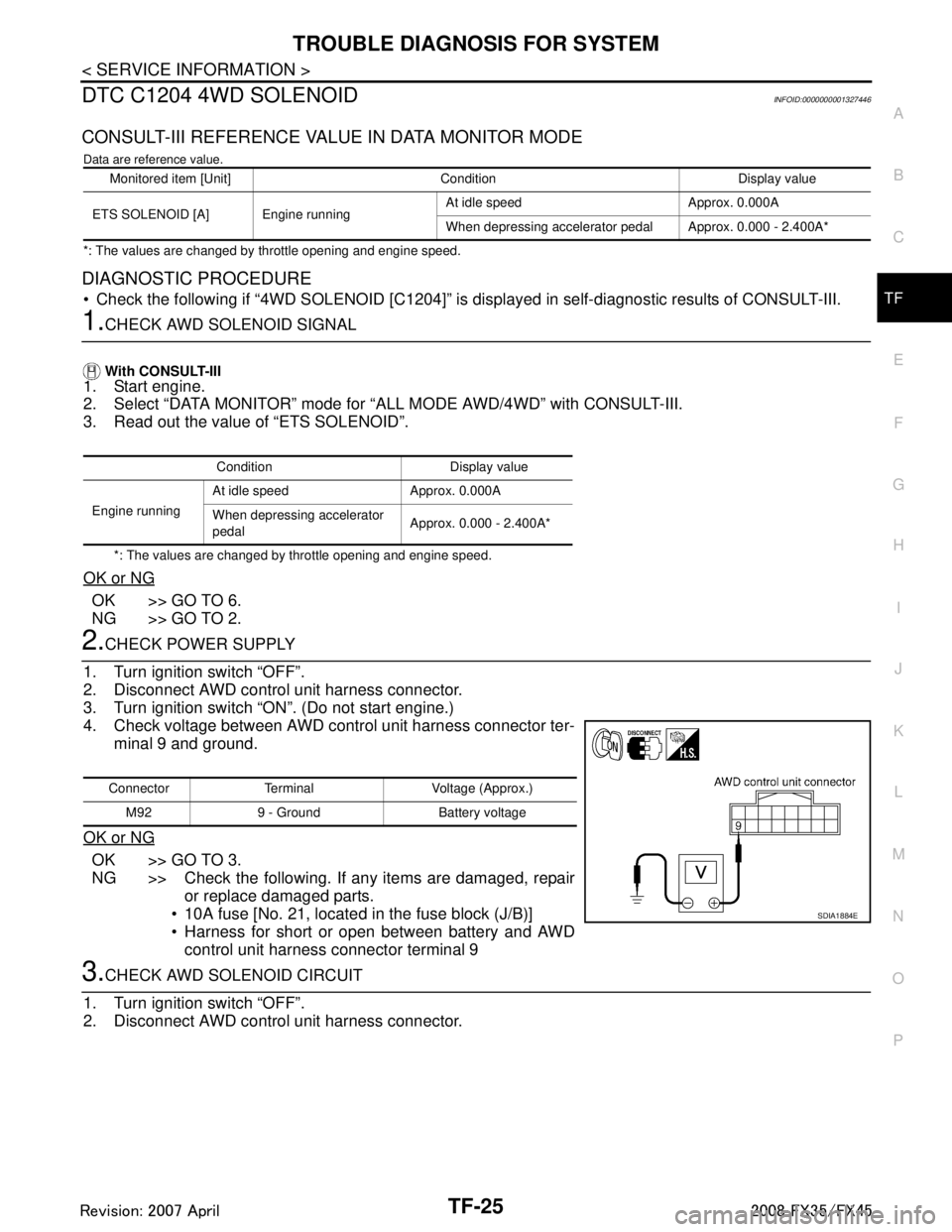
2.CHECK POWER SUPPLY
1. Turn ignition switch “OFF”.
2. Disconnect AWD control unit harness connector.
3. Turn ignition switch “ON”. (Do not start engine.)
4. Check voltage between AWD control unit harness connector ter- minal 9 and ground.
OK or NG
OK >> GO TO 3.
NG >> Check the following. If any items are damaged, repair or replace damaged parts.
10A fuse [No. 21, located in the fuse block (J/B)]
Harness for short or open between battery and AWD control unit harness connector terminal 9
3.CHECK AWD SOLENOID CIRCUIT
1. Turn ignition switch “OFF”.
2. Disconnect AWD control unit harness connector.
Monitored item [Unit] Condition Display value
ETS SOLENOID [A] Engine running At idle speed Approx. 0.000A
When depressing accelerator pedal Approx. 0.000 - 2.400A*
Condition Display value
Engine running At idle speed Approx. 0.000A
When depressing accelerator
pedal
Approx. 0.000 - 2.400A*
Connector Terminal Voltage (Approx.)
M92 9 - Ground Battery voltage
SDIA1884E
3AA93ABC3ACD3AC03ACA3AC03AC63AC53A913A773A893A873A873A8E3A773A983AC73AC93AC03AC3
3A893A873A873A8F3A773A9D3AAF3A8A3A8C3A863A9D3AAF3A8B3A8C