Page 2827 of 3924
FFD-36
< SERVICE INFORMATION >
FRONT FINAL DRIVE ASSEMBLY
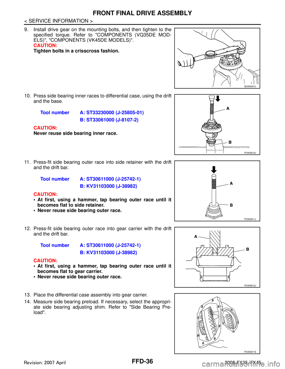
9. Install drive gear on the mounting bolts, and then tighten to thespecified torque. Refer to "COMPONENTS (VQ35DE MOD-
ELS)", "COMPONENTS (VK45DE MODELS)".
CAUTION:
Tighten bolts in a crisscross fashion.
10. Press side bearing inner races to differential case, using the drift and the base.
CAUTION:
Never reuse side bearing inner race.
11. Press-fit side bearing outer race into side retainer with the drift and the drift bar.
CAUTION:
At first, using a hammer, tap bearing outer race until itbecomes flat to side retainer.
Never reuse side bearing outer race.
12. Press-fit side bearing outer race into gear carrier with the drift and the drift bar.
CAUTION:
At first, using a hammer, tap bearing outer race until itbecomes flat to gear carrier.
Never reuse side bearing outer race.
13. Place the differential case assembly into gear carrier.
14. Measure side bearing preload. If necessary, select the appropri-
ate side bearing adjusting shim. Refer to "Side Bearing Pre-
load".
SDIA0247J
Tool number A: ST33230000 (J-25805-01)
B: ST33061000 (J-8107-2)
PDIA0810J
Tool number A: ST30611000 (J-25742-1)B: KV31103000 (J-38982)
PDIA0811J
Tool number A: ST30611000 (J-25742-1)B: KV31103000 (J-38982)
PDIA0812J
PDIA0671E
3AA93ABC3ACD3AC03ACA3AC03AC63AC53A913A773A893A873A873A8E3A773A983AC73AC93AC03AC3
3A893A873A873A8F3A773A9D3AAF3A8A3A8C3A863A9D3AAF3A8B3A8C
Page 2828 of 3924
FRONT FINAL DRIVE ASSEMBLYFFD-37
< SERVICE INFORMATION >
CEF
G H
I
J
K L
M A
B
FFD
N
O P
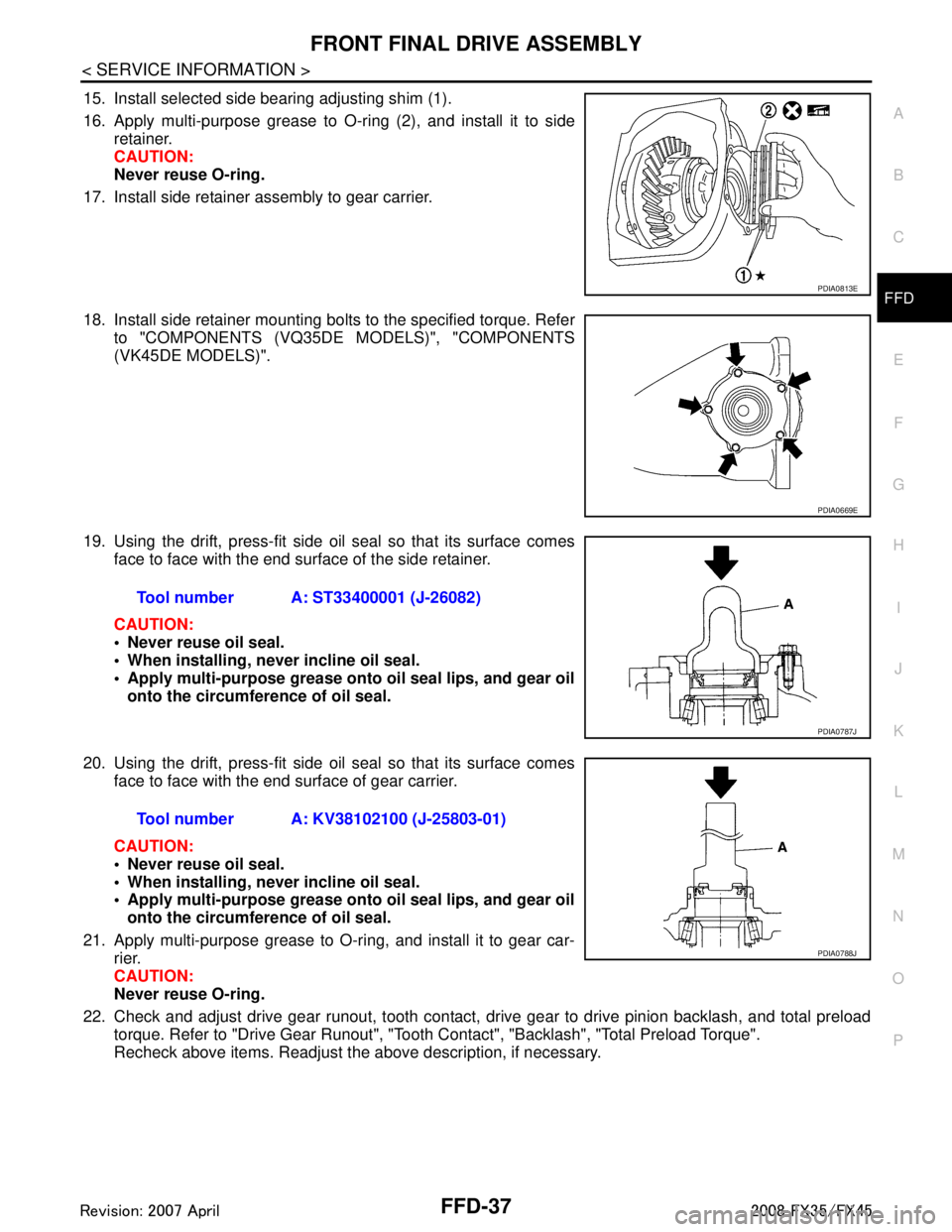
15. Install selected side bearing adjusting shim (1).
16. Apply multi-purpose grease to O-ring (2), and install it to side retainer.
CAUTION:
Never reuse O-ring.
17. Install side retainer assembly to gear carrier.
18. Install side retainer mounting bolts to the specified torque. Refer to "COMPONENTS (VQ35DE MODELS)", "COMPONENTS
(VK45DE MODELS)".
19. Using the drift, press-fit side oil seal so that its surface comes face to face with the end surface of the side retainer.
CAUTION:
Never reuse oil seal.
When installing, never incline oil seal.
Apply multi-purpose grease onto oil seal lips, and gear oilonto the circumference of oil seal.
20. Using the drift, press-fit side oil seal so that its surface comes face to face with the end surface of gear carrier.
CAUTION:
Never reuse oil seal.
When installing, never incline oil seal.
Apply multi-purpose grease onto oil seal lips, and gear oilonto the circumference of oil seal.
21. Apply multi-purpose grease to O-ring, and install it to gear car- rier.
CAUTION:
Never reuse O-ring.
22. Check and adjust drive gear runout, tooth contact, dr ive gear to drive pinion backlash, and total preload
torque. Refer to "Drive Gear Runout", "Tooth Contact", "Backlash", "Total Preload Torque".
Recheck above items. Readjust the above description, if necessary.
PDIA0813E
PDIA0669E
Tool number A: ST33400001 (J-26082)
PDIA0787J
Tool number A: KV38102100 (J-25803-01)
PDIA0788J
3AA93ABC3ACD3AC03ACA3AC03AC63AC53A913A773A893A873A873A8E3A773A983AC73AC93AC03AC3
3A893A873A873A8F3A773A9D3AAF3A8A3A8C3A863A9D3AAF3A8B3A8C
Page 2829 of 3924
FFD-38
< SERVICE INFORMATION >
FRONT FINAL DRIVE ASSEMBLY
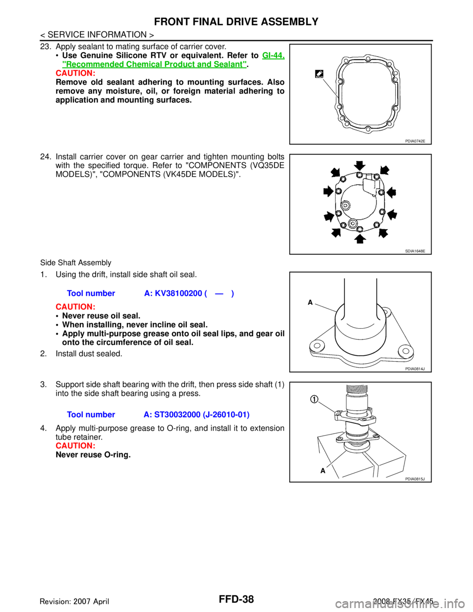
23. Apply sealant to mating surface of carrier cover.Use Genuine Silicone RTV or equivalent. Refer to GI-44,
"Recommended Chemical Product and Sealant".
CAUTION:
Remove old sealant adhering to mounting surfaces. Also
remove any moisture, oil, or foreign material adhering to
application and mounting surfaces.
24. Install carrier cover on gear carrier and tighten mounting bolts with the specified torque. Refer to "COMPONENTS (VQ35DE
MODELS)", "COMPONENT S (VK45DE MODELS)".
Side Shaft Assembly
1. Using the drift, install side shaft oil seal.
CAUTION:
Never reuse oil seal.
When installing, n ever incline oil seal.
Apply multi-purpose grease onto oil seal lips, and gear oil
onto the circumference of oil seal.
2. Install dust sealed.
3. Support side shaft bearing with the drift, then press side shaft (1) into the side shaft bearing using a press.
4. Apply multi-purpose grease to O-ring, and install it to extension tube retainer.
CAUTION:
Never reuse O-ring.
PDIA0742E
SDIA1648E
Tool number A: KV38100200 ( — )
PDIA0814J
Tool number A: ST30032000 (J-26010-01)
PDIA0815J
3AA93ABC3ACD3AC03ACA3AC03AC63AC53A913A773A893A873A873A8E3A773A983AC73AC93AC03AC3
3A893A873A873A8F3A773A9D3AAF3A8A3A8C3A863A9D3AAF3A8B3A8C
Page 2830 of 3924
SERVICE DATA AND SPECIFICATIONS (SDS)
FFD-39
< SERVICE INFORMATION >
C EF
G H
I
J
K L
M A
B
FFD
N
O P
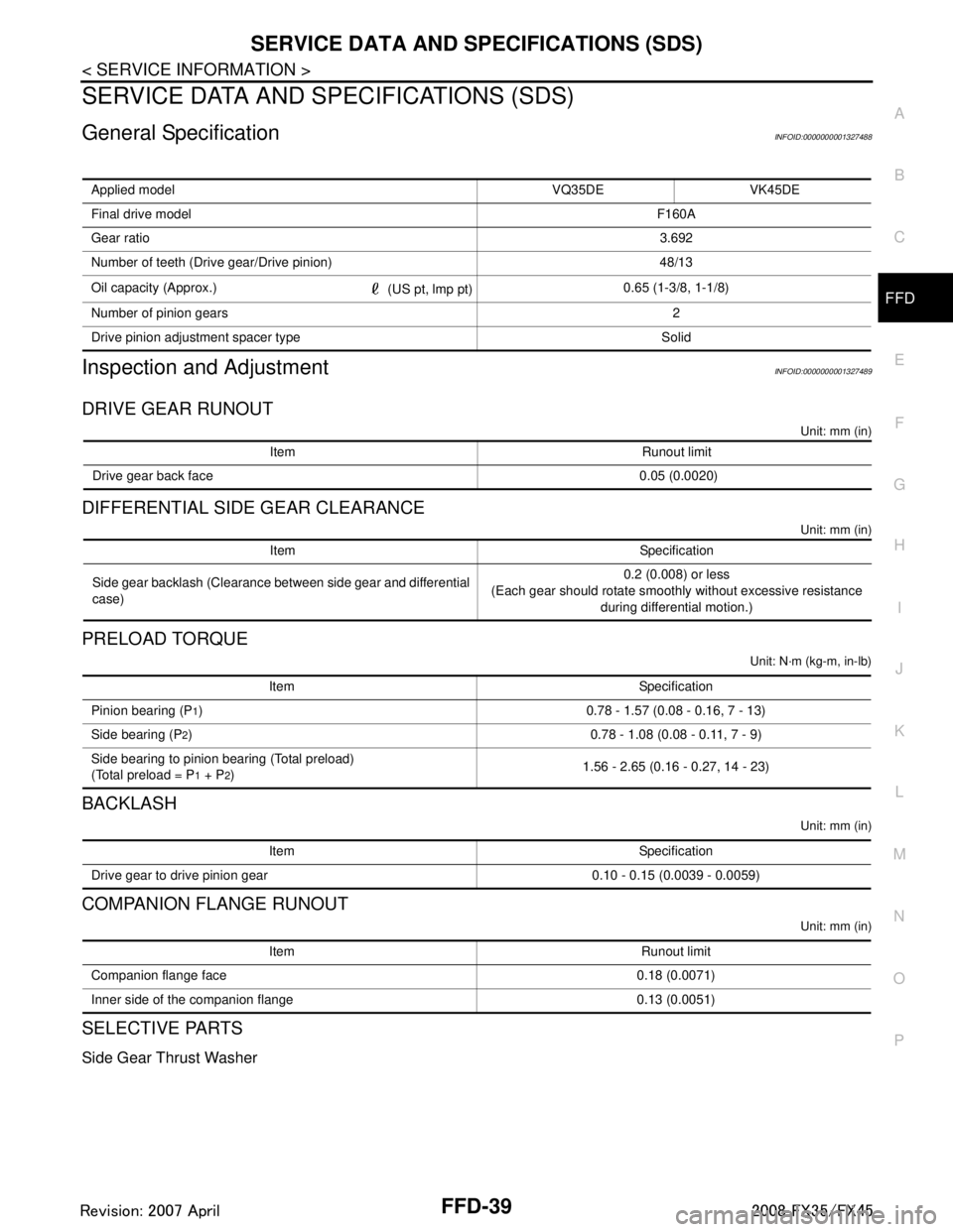
SERVICE DATA AND SPECIFICATIONS (SDS)
General SpecificationINFOID:0000000001327488
Inspection and AdjustmentINFOID:0000000001327489
DRIVE GEAR RUNOUT
Unit: mm (in)
DIFFERENTIAL SIDE GEAR CLEARANCE
Unit: mm (in)
PRELOAD TORQUE
Unit: N·m (kg-m, in-lb)
BACKLASH
Unit: mm (in)
COMPANION FLANGE RUNOUT
Unit: mm (in)
SELECTIVE PARTS
Side Gear Thrust Washer
Applied model VQ35DE VK45DE
Final drive model F160A
Gear ratio 3.692
Number of teeth (Drive gear/Drive pinion) 48/13
Oil capacity (Approx.) (US pt, lmp pt)0.65 (1-3/8, 1-1/8)
Number of pinion gears 2
Drive pinion adjustment spacer type Solid
Item Runout limit
Drive gear back face 0.05 (0.0020)
Item Specification
Side gear backlash (Clearance between side gear and differential
case) 0.2 (0.008) or less
(Each gear should rotate smoothly without excessive resistance during differential motion.)
Item Specification
Pinion bearing (P
1) 0.78 - 1.57 (0.08 - 0.16, 7 - 13)
Side bearing (P
2) 0.78 - 1.08 (0.08 - 0.11, 7 - 9)
Side bearing to pinion bearing (Total preload)
(Total preload = P
1 + P2) 1.56 - 2.65 (0.16 - 0.27, 14 - 23)
Item Specification
Drive gear to drive pinion gear 0.10 - 0.15 (0.0039 - 0.0059)
Item Runout limit
Companion flange face 0.18 (0.0071)
Inner side of the companion flange 0.13 (0.0051)
3AA93ABC3ACD3AC03ACA3AC03AC63AC53A913A773A893A873A873A8E3A773A983AC73AC93AC03AC3
3A893A873A873A8F3A773A9D3AAF3A8A3A8C3A863A9D3AAF3A8B3A8C
Page 2847 of 3924
PREPARATIONFSU-3
< SERVICE INFORMATION >
C
DF
G H
I
J
K L
M A
B
FSU
N
O P
PREPARATION
Special Service ToolINFOID:0000000001327534
The actual shapes of Kent-Moore tools may differ fr om those of special service tools illustrated here.
Commercial Service ToolINFOID:0000000001327535
Tool number
(Kent-Moore No.)
Tool name Description
HT72520000
(J-25730-A)
Ball joint remover
a: 33 mm (1.30 in)
b: 50 mm (1.97 in)
r: 11.5 mm (0.453 in) Removing steering outer socket
Removing transverse link
ST35652000
( — )
Strut attachment Disassembling and assembling strut
ST3127 S000
(See J-25765-A)
Preload gauge Measuring rotating torque of ball joint
NT546
ZZA0807D
ZZA0806D
Tool name
Description
Spring compressor Removing coil spring
Power tool Loosening bolts and nuts
S-NT717
PBIC0190E
3AA93ABC3ACD3AC03ACA3AC03AC63AC53A913A773A893A873A873A8E3A773A983AC73AC93AC03AC3
3A893A873A873A8F3A773A9D3AAF3A8A3A8C3A863A9D3AAF3A8B3A8C
Page 2853 of 3924
FRONT SUSPENSION ASSEMBLYFSU-9
< SERVICE INFORMATION >
C
DF
G H
I
J
K L
M A
B
FSU
N
O P
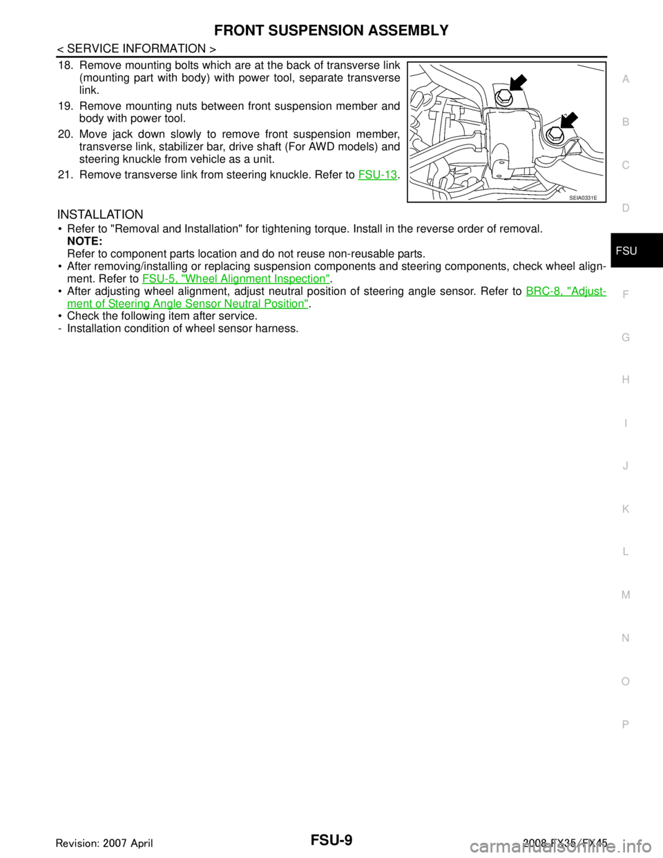
18. Remove mounting bolts which are at the back of transverse link (mounting part with body) with power tool, separate transverse
link.
19. Remove mounting nuts between front suspension member and body with power tool.
20. Move jack down slowly to remove front suspension member, transverse link, stabilizer bar, drive shaft (For AWD models) and
steering knuckle from vehicle as a unit.
21. Remove transverse link from steering knuckle. Refer to FSU-13
.
INSTALLATION
Refer to "Removal and Installation" for tightening torque. Install in the reverse order of removal.
NOTE:
Refer to component parts location and do not reuse non-reusable parts.
After removing/installing or replacing suspensi on components and steering components, check wheel align-
ment. Refer to FSU-5, "
Wheel Alignment Inspection".
After adjusting wheel alignment, adjust neutral position of steering angle sensor. Refer to BRC-8, "
Adjust-
ment of Steering Angle Sensor Neutral Position".
Check the following item after service.
- Installation condition of wheel sensor harness.
SEIA0331E
3AA93ABC3ACD3AC03ACA3AC03AC63AC53A913A773A893A873A873A8E3A773A983AC73AC93AC03AC3
3A893A873A873A8F3A773A9D3AAF3A8A3A8C3A863A9D3AAF3A8B3A8C
Page 2854 of 3924
FSU-10
< SERVICE INFORMATION >
COIL SPRING AND STRUT
COIL SPRING AND STRUT
Removal and InstallationINFOID:0000000001327540
REMOVAL
1. Remove tires from vehicle with power tool.
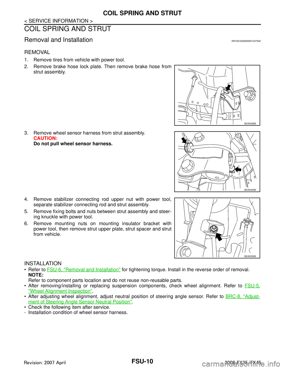
2. Remove brake hose lock plate. Then remove brake hose fromstrut assembly.
3. Remove wheel sensor harness from strut assembly. CAUTION:
Do not pull wheel sensor harness.
4. Remove stabilizer connecting rod upper nut with power tool, separate stabilizer connecting rod and strut assembly.
5. Remove fixing bolts and nuts between strut assembly and steer- ing knuckle with power tool.
6. Remove mounting nuts on mounting insulator bracket with power tool, then remove strut upper plate, strut spacer and strut
from vehicle.
INSTALLATION
Refer to FSU-6, "Removal and Installation" for tightening torque. Install in the reverse order of removal.
NOTE:
Refer to component parts location and do not reuse non-reusable parts.
After removing/installing or replacing suspension components, check wheel alignment. Refer to FSU-5,
"Wheel Alignment Inspection".
After adjusting wheel alignment, adjust neutral position of steering angle sensor. Refer to BRC-8, "
Adjust-
ment of Steering Angle Sensor Neutral Position".
Check the following item after service.
- Installation condition of wheel sensor harness.
SEIA0328E
SEIA0329E
SEIA0330E
3AA93ABC3ACD3AC03ACA3AC03AC63AC53A913A773A893A873A873A8E3A773A983AC73AC93AC03AC3
3A893A873A873A8F3A773A9D3AAF3A8A3A8C3A863A9D3AAF3A8B3A8C
Page 2856 of 3924
FSU-12
< SERVICE INFORMATION >
COIL SPRING AND STRUT
Make sure piston rod on strut is not damaged when attaching components to strut.
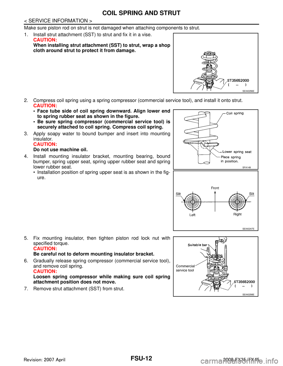
1. Install strut attachment (SST) to strut and fix it in a vise.CAUTION:
When installing strut attachment (SST) to strut, wrap a shop
cloth around strut to protect it from damage.
2. Compress coil spring using a spring compressor (c ommercial service tool), and install it onto strut.
CAUTION:
Face tube side of coil spri ng downward. Align lower end
to spring rubber seat as shown in the figure.
Be sure spring compressor (commercial service tool) is securely attached to coil sp ring. Compress coil spring.
3. Apply soapy water to bound bumper and insert into mounting insulator.
CAUTION:
Do not use machine oil.
4. Install mounting insulator bracket, mounting bearing, bound bumper, spring upper seat, spring upper rubber seat and spring
lower rubber seat.
Installation position of spring upper seat is as shown in the fig-ure.
5. Fix mounting insulator, then tighten piston rod lock nut with specified torque.
CAUTION:
Be careful not to deform mounting insulator bracket.
6. Gradually release spring compressor (commercial service tool), and remove coil spring.
CAUTION:
Loosen spring compressor whil e making sure coil spring
attachment position does not move.
7. Remove strut attachment (SST) from strut.
SEIA0296E
SFA149
SEIA0247E
SEIA0298E
3AA93ABC3ACD3AC03ACA3AC03AC63AC53A913A773A893A873A873A8E3A773A983AC73AC93AC03AC3
3A893A873A873A8F3A773A9D3AAF3A8A3A8C3A863A9D3AAF3A8B3A8C