2008 INFINITI FX35 torque
[x] Cancel search: torquePage 2801 of 3924
FFD-10
< SERVICE INFORMATION >
FRONT OIL SEAL
INSTALLATION
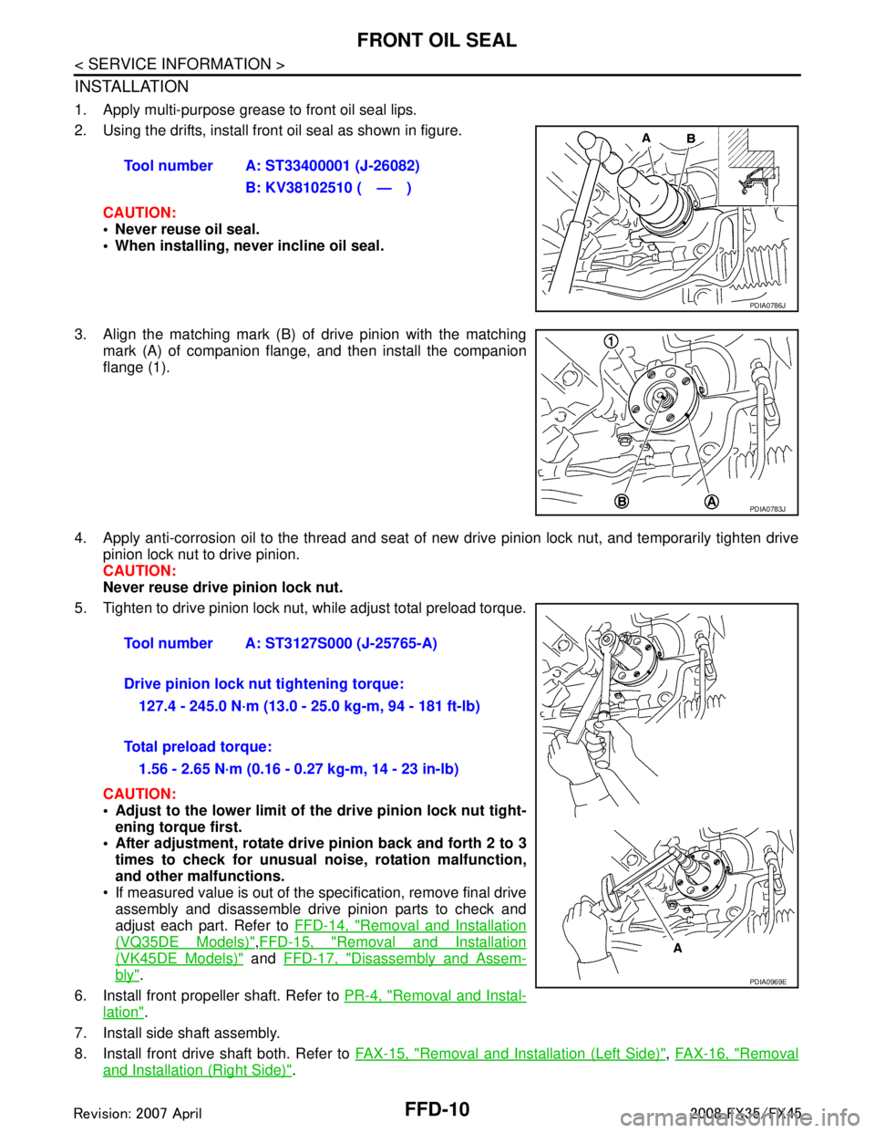
1. Apply multi-purpose grease to front oil seal lips.
2. Using the drifts, install front oil seal as shown in figure.CAUTION:
• Never reuse oil seal.
When installing, n ever incline oil seal.
3. Align the matching mark (B) of drive pinion with the matching mark (A) of companion flange, and then install the companion
flange (1).
4. Apply anti-corrosion oil to the thread and seat of new drive pinion lock nut, and temporarily tighten drive
pinion lock nut to drive pinion.
CAUTION:
Never reuse drive pinion lock nut.
5. Tighten to drive pinion lock nut, while adjust total preload torque.
CAUTION:
Adjust to the lower limit of the drive pinion lock nut tight-
ening torque first.
After adjustment, rotate dri ve pinion back and forth 2 to 3
times to check for unusual no ise, rotation malfunction,
and other malfunctions.
If measured value is out of the specification, remove final drive assembly and disassemble drive pinion parts to check and
adjust each part. Refer to FFD-14, "
Removal and Installation
(VQ35DE Models)",FFD-15, "Removal and Installation
(VK45DE Models)" and FFD-17, "Disassembly and Assem-
bly".
6. Install front propeller shaft. Refer to PR-4, "
Removal and Instal-
lation".
7. Install side shaft assembly.
8. Install front drive shaft both. Refer to FAX-15, "
Removal and Installation (Left Side)", FAX-16, "Removal
and Installation (Right Side)".
Tool number A: ST33400001 (J-26082)
B: KV38102510 ( — )
PDIA0786J
PDIA0783J
Tool number A: ST3127S000 (J-25765-A)
Drive pinion lock nut tightening torque:127.4 - 245.0 N·m (13.0 - 25.0 kg-m, 94 - 181 ft-lb)
Total preload torque: 1.56 - 2.65 N·m (0.16 - 0.27 kg-m, 14 - 23 in-lb)
PDIA0969E
3AA93ABC3ACD3AC03ACA3AC03AC63AC53A913A773A893A873A873A8E3A773A983AC73AC93AC03AC3
3A893A873A873A8F3A773A9D3AAF3A8A3A8C3A863A9D3AAF3A8B3A8C
Page 2805 of 3924
FFD-14
< SERVICE INFORMATION >
FRONT FINAL DRIVE ASSEMBLY
FRONT FINAL DRIVE ASSEMBLY
Removal and Installation (VQ35DE Models)INFOID:0000000001327485
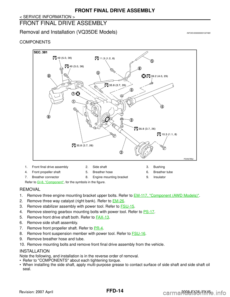
COMPONENTS
REMOVAL
1. Remove three engine mounting bracket upper bolts. Refer to EM-117, "Component (AWD Models)".
2. Remove three way catalyst (right bank). Refer to EM-26
.
3. Remove stabilizer assembly with power tool. Refer to FSU-15
.
4. Remove steering gearbox mounting bolts with power tool. Refer to PS-17
.
5. Remove front drive shaft both. Refer to FA X - 1 3
.
6. Remove side shaft assembly.
7. Remove front propeller shaft. Refer to PR-4
.
8. Remove front suspension member with power tool. Refer to FSU-16
.
9. Remove breather hose and tube.
10. Remove mounting bolts and remove front final drive assembly from the vehicle.
INSTALLATION
Note the following, and installation is in the reverse order of removal.
Refer to "COMPONENTS" about each tightening torque.
When installing the side shaft, apply multi-purpose grease to contact surface of side shaft and side shaft oil
seal.
1. Front final drive assembly 2. Side shaft 3. Bushing
4. Front propeller shaft 5. Breather hose 6. Breather tube
7. Breather connector 8. Engine mounting bracket 9. Insulator
Refer to GI-8, "
Component", for the symbols in the figure.
PDIA0789J
3AA93ABC3ACD3AC03ACA3AC03AC63AC53A913A773A893A873A873A8E3A773A983AC73AC93AC03AC3
3A893A873A873A8F3A773A9D3AAF3A8A3A8C3A863A9D3AAF3A8B3A8C
Page 2807 of 3924
FFD-16
< SERVICE INFORMATION >
FRONT FINAL DRIVE ASSEMBLY
REMOVAL
1. Remove three way catalyst (right bank). Refer to EM-179.
2. Remove stabilizer assembly with power tool. Refer to FSU-15
.
3. Remove steering gearbox mounting bolts with power tool. Refer to PS-17
.
4. Remove front drive shaft both. Refer to FA X - 1 3
.
5. Remove side shaft assembly.
6. Remove front propeller shaft. Refer to PR-4
.
7. Remove front suspension member with power tool. Refer to FSU-16
.
8. Remove engine wire harness clamp bolts from front final drive.
9. Remove breather hose and tube.
10. Remove mounting bolts and remove front final drive assembly from the vehicle.
INSTALLATION
Note the following, and installation is in the reverse order of removal.
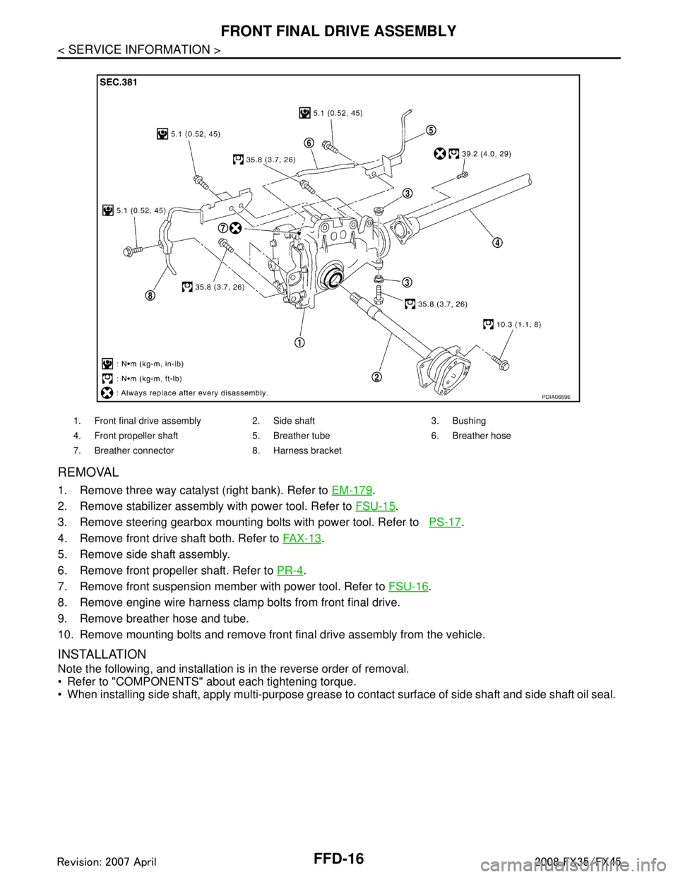
Refer to "COMPONENTS" about each tightening torque.
When installing side shaft, apply multi-purpose grease to contact surface of side shaft and side shaft oil seal.
1. Front final drive assembly 2. Side shaft 3. Bushing
4. Front propeller shaft 5. Breather tube 6. Breather hose
7. Breather connector 8. Harness bracket
PDIA0659E
3AA93ABC3ACD3AC03ACA3AC03AC63AC53A913A773A893A873A873A8E3A773A983AC73AC93AC03AC3
3A893A873A873A8F3A773A9D3AAF3A8A3A8C3A863A9D3AAF3A8B3A8C
Page 2811 of 3924
FFD-20
< SERVICE INFORMATION >
FRONT FINAL DRIVE ASSEMBLY
ASSEMBLY INSPECTION AND ADJUSTMENT
Before inspection and adjustment, drain gear oil.
Total Preload Torque
1. Rotate drive pinion back and forth 2 to 3 times to check for unusual noise and rotation malfunction.
2. Rotate drive pinion at least 20 times to check for smooth operation of the bearing.
3. Measure total preload with preload gauge.NOTE:
Total preload torque = Pinion bearing preload torque + Side
bearing preload torque
If measured value is out of the specification, disassemble it to check and adjust each part. Adjust the pinion bearing preload and
side bearing preload.
Adjust the pinion bearing preload first, then adjust the side bearing preload.
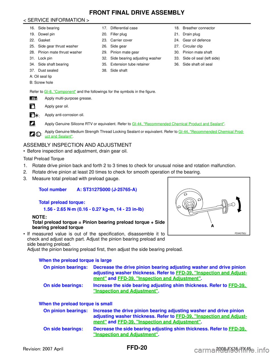
16. Side bearing 17. Differential case 18. Breather connector
19. Dowel pin 20. Filler plug 21. Drain plug
22. Gasket 23. Carrier cover 24. Gear oil defence
25. Side gear thrust washer 26. Side gear 27. Circular clip
28. Pinion mate thrust washer 29. Pinion mate gear 30. Pinion mate shaft
31. Lock pin 32. Side bearing adjusting washer 33. Side oil seal (left side)
34. Side shaft bearing 35. Extension tube retainer 36. Side shaft oil seal
37. Dust sealed 38. Side shaft
A: Oil seal lip
B: Screw hole
Refer to GI-8, "
Component" and the followings for the symbols in the figure.
: Apply multi-purpose grease.
: Apply gear oil.
: Apply anti-corrosion oil.
: Apply Genuine Silicone RTV or equivalent. Refer to
GI-44, "
Recommended Chemical Product and Sealant".
: Apply Genuine Medium Strength Thread Locking Sealant or equivalent. Refer to
GI-44, "
Recommended Chemical Prod-
uct and Sealant".
Tool number A: ST3127S000 (J-25765-A)
Total preload torque:
1.56 - 2.65 N·m (0.16 - 0.27 kg-m, 14 - 23 in-lb)
PDIA0792J
When the preload torque is largeOn pinion bearings: Decrease the drive pinion bearing adjusting washer and drive pinion
adjusting washer thickness. Refer to FFD-39, "
Inspection and Adjust-
ment" and FFD-39, "Inspection and Adjustment".
On side bearings: Increase the side bear ing adjusting shim thickness. Refer to FFD-39,
"Inspection and Adjustment".
When the preload torque is small On pinion bearings: Increase the drive pinion bearing adjusting washer and drive pinion
adjusting washer thickness. Refer to FFD-39, "
Inspection and Adjust-
ment" and FFD-39, "Inspection and Adjustment".
On side bearings: Decrease the side bearin g adjusting shim thickness. Refer to FFD-39,
"Inspection and Adjustment".
3AA93ABC3ACD3AC03ACA3AC03AC63AC53A913A773A893A873A873A8E3A773A983AC73AC93AC03AC3
3A893A873A873A8F3A773A9D3AAF3A8A3A8C3A863A9D3AAF3A8B3A8C
Page 2821 of 3924
FFD-30
< SERVICE INFORMATION >
FRONT FINAL DRIVE ASSEMBLY
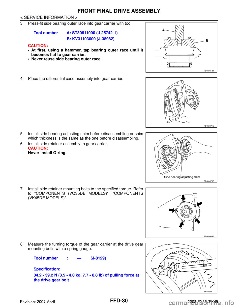
3. Press-fit side bearing outer race into gear carrier with tool.CAUTION:
At first, using a hammer, tap bearing outer race until itbecomes flat to gear carrier.
Never reuse side bearing outer race.
4. Place the differential case assembly into gear carrier.
5. Install side bearing adjusting shim before disassembling or shim which thickness is the same as the one before disassembling.
6. Install side retainer assembly to gear carrier. CAUTION:
Never install O-ring.
7. Install side retainer mounting bolts to the specified torque. Refer to "COMPONENTS (VQ35DE MODELS)", "COMPONENTS
(VK45DE MODELS)".
8. Measure the turning torque of the gear carrier at the drive gear
mounting bolts with a spring gauge. Tool number A: ST30611000 (J-25742-1)
B: KV31103000 (J-38982)
PDIA0812J
PDIA0671E
PDIA0678E
PDIA0669E
Tool number : — (J-8129)
Specification:
34.2 - 39.2 N (3.5 - 4.0 kg, 7.7 - 8.8 lb) of pulling force at
the drive gear bolt
SPD194A
3AA93ABC3ACD3AC03ACA3AC03AC63AC53A913A773A893A873A873A8E3A773A983AC73AC93AC03AC3
3A893A873A873A8F3A773A9D3AAF3A8A3A8C3A863A9D3AAF3A8B3A8C
Page 2822 of 3924
FRONT FINAL DRIVE ASSEMBLYFFD-31
< SERVICE INFORMATION >
CEF
G H
I
J
K L
M A
B
FFD
N
O P
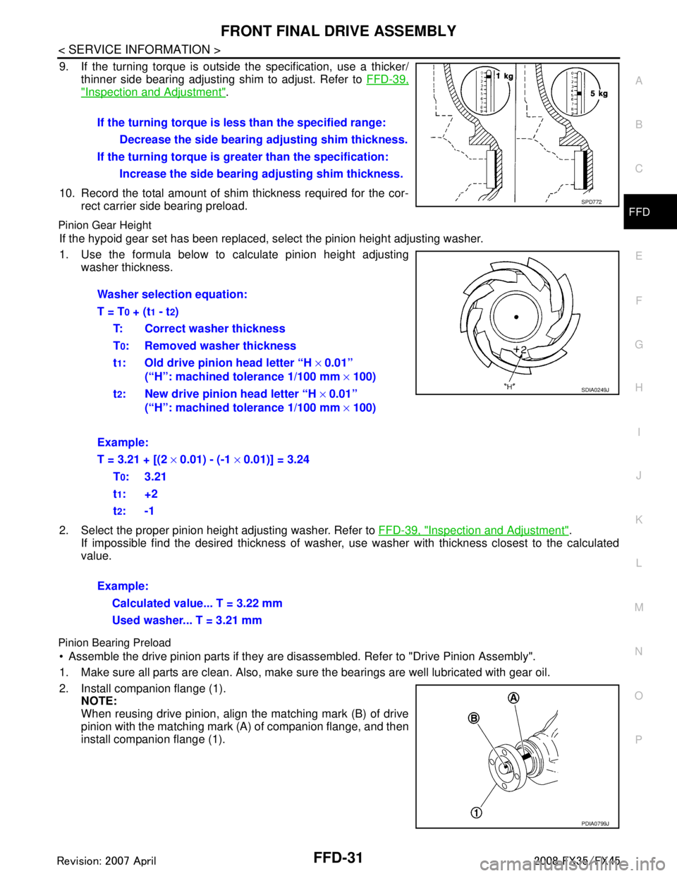
9. If the turning torque is outside the specification, use a thicker/ thinner side bearing adjusting shim to adjust. Refer to FFD-39,
"Inspection and Adjustment".
10. Record the total amount of shim thickness required for the cor- rect carrier side bearing preload.
Pinion Gear Height
If the hypoid gear set has been replaced, se lect the pinion height adjusting washer.
1. Use the formula below to calculate pinion height adjusting washer thickness.
2. Select the proper pinion height adjusting washer. Refer to FFD-39, "
Inspection and Adjustment".
If impossible find the desired thickness of washer, us e washer with thickness closest to the calculated
value.
Pinion Bearing Preload
Assemble the drive pinion parts if they are disassembled. Refer to "Drive Pinion Assembly".
1. Make sure all parts are clean. Also, make sure the bearings are well lubricated with gear oil.
2. Install companion flange (1). NOTE:
When reusing drive pinion, align the matching mark (B) of drive
pinion with the matching mark (A) of companion flange, and then
install companion flange (1).If the turning torque is l
ess than the specified range:
Decrease the side bearing adjusting shim thickness.
If the turning torque is gr eater than the specification:
Increase the side bearing adjusting shim thickness.
SPD772
Washer selection equation:
T = T
0 + (t1 - t2)
T: Correct washer thickness
T
0: Removed washer thickness
t
1: Old drive pinion head letter “H × 0.01”
(“H”: machined tolerance 1/100 mm × 100)
t
2: New drive pinion head letter “H × 0.01”
(“H”: machined tolerance 1/100 mm × 100)
Example:
T = 3.21 + [(2 × 0.01) - (-1 × 0.01)] = 3.24
T
0:3.21
t
1:+2
t
2:-1
Example: Calculated value... T = 3.22 mm
Used washer... T = 3.21 mm
SDIA0249J
PDIA0799J
3AA93ABC3ACD3AC03ACA3AC03AC63AC53A913A773A893A873A873A8E3A773A983AC73AC93AC03AC3
3A893A873A873A8F3A773A9D3AAF3A8A3A8C3A863A9D3AAF3A8B3A8C
Page 2823 of 3924
FFD-32
< SERVICE INFORMATION >
FRONT FINAL DRIVE ASSEMBLY
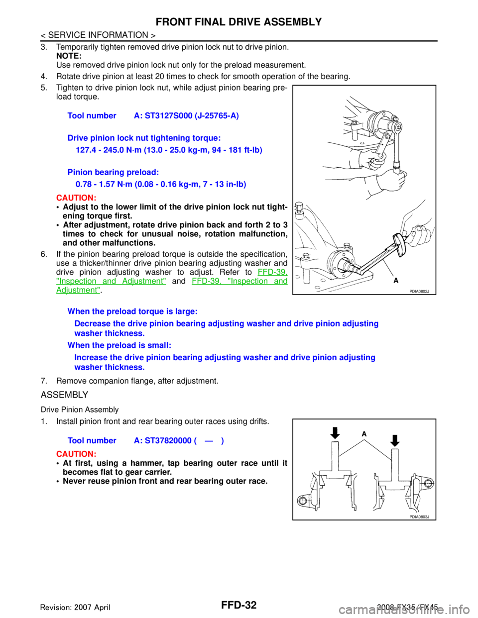
3. Temporarily tighten removed drive pinion lock nut to drive pinion.NOTE:
Use removed drive pinion lock nut only for the preload measurement.
4. Rotate drive pinion at least 20 times to check for smooth operation of the bearing.
5. Tighten to drive pinion lock nut, while adjust pinion bearing pre- load torque.
CAUTION:
Adjust to the lower limit of the drive pinion lock nut tight-
ening torque first.
After adjustment, rotate dri ve pinion back and forth 2 to 3
times to check for unusual no ise, rotation malfunction,
and other malfunctions.
6. If the pinion bearing preload torque is outside the specification, use a thicker/thinner drive pinion bearing adjusting washer and
drive pinion adjusting washer to adjust. Refer to FFD-39,
"Inspection and Adjustment" and FFD-39, "Inspection and
Adjustment".
7. Remove companion flange, after adjustment.
ASSEMBLY
Drive Pinion Assembly
1. Install pinion front and rear bearing outer races using drifts. CAUTION:
At first, using a hammer, tap bearing outer race until itbecomes flat to gear carrier.
Never reuse pinion front and rear bearing outer race. Tool number A: ST3127S000 (J-25765-A)
Drive pinion lock nut tightening torque:
127.4 - 245.0 N·m (13.0 - 25.0 kg-m, 94 - 181 ft-lb)
Pinion bearing preload: 0.78 - 1.57 N·m (0.08 - 0.16 kg-m, 7 - 13 in-lb)
When the preload torque is large: Decrease the drive pinion b earing adjusting washer and drive pinion adjusting
washer thickness.
When the preload is small: Increase the drive pinion bearing adjusti ng washer and drive pinion adjusting
washer thickness.
PDIA0802J
Tool number A: ST37820000 ( — )
PDIA0803J
3AA93ABC3ACD3AC03ACA3AC03AC63AC53A913A773A893A873A873A8E3A773A983AC73AC93AC03AC3
3A893A873A873A8F3A773A9D3AAF3A8A3A8C3A863A9D3AAF3A8B3A8C
Page 2825 of 3924
FFD-34
< SERVICE INFORMATION >
FRONT FINAL DRIVE ASSEMBLY
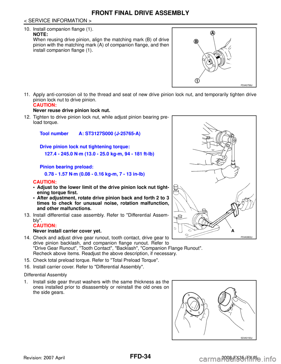
10. Install companion flange (1).NOTE:
When reusing drive pinion, align the matching mark (B) of drive
pinion with the matching mark (A) of companion flange, and then
install companion flange (1).
11. Apply anti-corrosion oil to the thread and seat of new drive pinion lock nut, and temporarily tighten drive
pinion lock nut to drive pinion.
CAUTION:
Never reuse drive pinion lock nut.
12. Tighten to drive pinion lock nut, while adjust pinion bearing pre- load torque.
CAUTION:
Adjust to the lower limit of the drive pinion lock nut tight-
ening torque first.
After adjustment, rotate dri ve pinion back and forth 2 to 3
times to check for unusual no ise, rotation malfunction,
and other malfunctions.
13. Install differential case assembly. Refer to "Differential Assem- bly".
CAUTION:
Never install carrier cover yet.
14. Check and adjust drive gear runout, tooth contact, drive gear to drive pinion backlash, and companion flange runout. Refer to
"Drive Gear Runout", "Tooth Contact" , "Backlash", "Companion Flange Runout".
Recheck above items. Readjust the above description, if necessary.
15. Check total preload torque. Refer to "Total Preload Torque".
16. Install carrier cover. Refer to "Differential Assembly".
Differential Assembly
1. Install side gear thrust washers with the same thickness as the ones installed prior to disassembly or reinstall the old ones on
the side gears.
PDIA0799J
Tool number A: ST3127S000 (J-25765-A)
Drive pinion lock nut tightening torque:
127.4 - 245.0 N·m (13.0 - 25.0 kg-m, 94 - 181 ft-lb)
Pinion bearing preload: 0.78 - 1.57 N·m (0.08 - 0.16 kg-m, 7 - 13 in-lb)
PDIA0802J
SDIA0193J
3AA93ABC3ACD3AC03ACA3AC03AC63AC53A913A773A893A873A873A8E3A773A983AC73AC93AC03AC3
3A893A873A873A8F3A773A9D3AAF3A8A3A8C3A863A9D3AAF3A8B3A8C