2008 INFINITI FX35 power supply
[x] Cancel search: power supplyPage 1232 of 3924
DI-106
< SERVICE INFORMATION >
REAR VIEW MONITOR
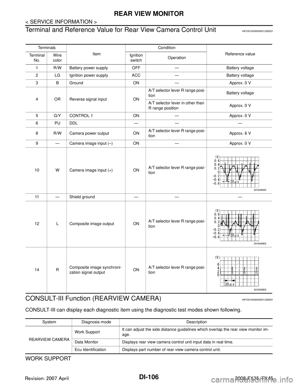
Terminal and Reference Value for Rear View Camera Control Unit
INFOID:0000000001328533
CONSULT-III Function (REARVIEW CAMERA)INFOID:0000000001328534
CONSULT-III can display each diagnostic item using the diagnostic test modes shown following.
WORK SUPPORT
Te r m i n a l s
Item Condition
Reference value
Te r m i n a l
No. Wire
color Ignition
switch Operation
1 R/W Battery power supply OFF — Battery voltage
2 LG Ignition power supply ACC — Battery voltage
3 B Ground ON — Approx. 0 V
4 OR Reverse signal input ON A/T selector lever R range posi-
tion
Battery voltage
A/T selector lever in other than
R range position Approx. 0 V
5 G/Y CONTROL 1 ON — Approx. 0 V
6PUDDL — — —
8 R/W Camera power output ON A/T selector lever R range posi-
tion
Approx. 6 V
9 — Camera image input (–) ON — Approx. 0 V
10 W Camera image input (+) ON A/T selector lever R range posi-
tion
11 — Shield ground — — —
12 L Composite image output ON A/T selector lever R range posi-
tion
14 R Composite image synchroni-
zation signal output ONA/T selector lever R range posi-
tion
SKIA4894E
SKIA4896E
SKIA5896E
System Diagnosis mode Description
REARVIEW CAMERA Work Support
It can adjust the side distance guidelines which overlap the rear view monitor im-
age.
Data Monitor Displays rear view camera control unit input data in real time.
Ecu Identification Displays part number of rear view camera control unit.
3AA93ABC3ACD3AC03ACA3AC03AC63AC53A913A773A893A873A873A8E3A773A983AC73AC93AC03AC3
3A893A873A873A8F3A773A9D3AAF3A8A3A8C3A863A9D3AAF3A8B3A8C
Page 1234 of 3924
DI-108
< SERVICE INFORMATION >
REAR VIEW MONITOR
6. Select “SAVE”, and confirm the guide line.
7. Select “End”.
8. Select “ADJ GUIDELINE POSITION”.
9. Adjust the guide line selecting “X UP”, “X DOWN”, “Y UP” or “Y DOWN” so that the corrected line can fit
the guide line.
10. Touch “SAVE”, and confirm the guide line.
11. Touch “End” to finish correcting.
Power Supply and Ground Circuit InspectionINFOID:0000000001328536
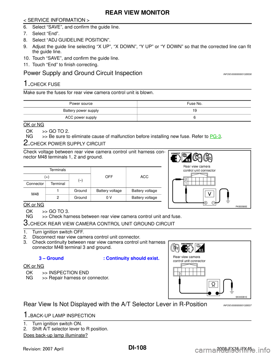
1.CHECK FUSE
Make sure the fuses for rear view camera control unit is blown.
OK or NG
OK >> GO TO 2.
NG >> Be sure to eliminate cause of malfunction before installing new fuse. Refer to PG-3
.
2.CHECK POWER SUPPLY CIRCUIT
Check voltage between rear view camera control unit harness con-
nector M48 terminals 1, 2 and ground.
OK or NG
OK >> GO TO 3.
NG >> Check harness between rear view camera control unit and fuse.
3.CHECK REAR VIEW CAMERA CONTROL UNIT GROUND CIRCUIT
1. Turn ignition switch OFF.
2. Disconnect rear view camera control unit connector.
3. Check continuity between rear view camera control unit harness connector M48 terminal 3 and ground.
OK or NG
OK >> INSPECTION END
NG >> Repair harness or connector.
Rear View Is Not Displayed with the A/T Selector Lever in R-PositionINFOID:0000000001328537
1.BACK-UP LAMP INSPECTION
1. Turn ignition switch ON.
2. Shift A/T selector lever to R position.
Does back-up lamp illuminate?
Power source Fuse No.
Battery power supply 19 ACC power supply 6
Te r m i n a l s OFF ACC
(+)
(–)
Connector Terminal
M48 1 Ground Battery voltage Battery voltage
2 Ground 0 V Battery voltage
PKIB3580E
3 – Ground : Continuity should exist.
SKIA5081E
3AA93ABC3ACD3AC03ACA3AC03AC63AC53A913A773A893A873A873A8E3A773A983AC73AC93AC03AC3
3A893A873A873A8F3A773A9D3AAF3A8A3A8C3A863A9D3AAF3A8B3A8C
Page 1236 of 3924
DI-110
< SERVICE INFORMATION >
REAR VIEW MONITOR
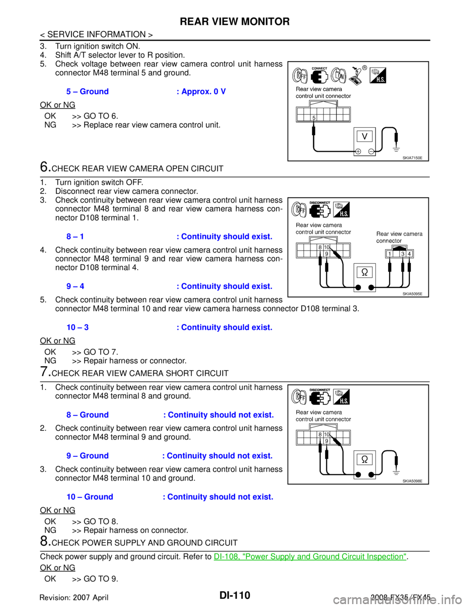
3. Turn ignition switch ON.
4. Shift A/T selector lever to R position.
5. Check voltage between rear view camera control unit harnessconnector M48 terminal 5 and ground.
OK or NG
OK >> GO TO 6.
NG >> Replace rear view camera control unit.
6.CHECK REAR VIEW CAMERA OPEN CIRCUIT
1. Turn ignition switch OFF.
2. Disconnect rear view camera connector.
3. Check continuity between rear view camera control unit harness connector M48 terminal 8 and rear view camera harness con-
nector D108 terminal 1.
4. Check continuity between rear view camera control unit harness connector M48 terminal 9 and rear view camera harness con-
nector D108 terminal 4.
5. Check continuity between rear view camera control unit harness connector M48 terminal 10 and rear view ca mera harness connector D108 terminal 3.
OK or NG
OK >> GO TO 7.
NG >> Repair harness or connector.
7.CHECK REAR VIEW CAMERA SHORT CIRCUIT
1. Check continuity between rear view camera control unit harness connector M48 terminal 8 and ground.
2. Check continuity between rear view camera control unit harness connector M48 terminal 9 and ground.
3. Check continuity between rear view camera control unit harness connector M48 terminal 10 and ground.
OK or NG
OK >> GO TO 8.
NG >> Repair harness on connector.
8.CHECK POWER SUPPLY AND GROUND CIRCUIT
Check power supply and ground circuit. Refer to DI-108, "
Power Supply and Ground Circuit Inspection".
OK or NG
OK >> GO TO 9. 5 – Ground : Approx. 0 V
SKIA7150E
8 – 1 : Continuity should exist.
9 – 4 : Continuity should exist.
10 – 3 : Continuity should exist.
SKIA5095E
8 – Ground : Continuity should not exist.
9 – Ground : Continuity should not exist.
10 – Ground : Continuity should not exist.
SKIA5098E
3AA93ABC3ACD3AC03ACA3AC03AC63AC53A913A773A893A873A873A8E3A773A983AC73AC93AC03AC3
3A893A873A873A8F3A773A9D3AAF3A8A3A8C3A863A9D3AAF3A8B3A8C
Page 1237 of 3924
REAR VIEW MONITORDI-111
< SERVICE INFORMATION >
C
DE
F
G H
I
J
L
M A
B
DI
N
O P
NG >> Repair or replace power supply and ground circuit.
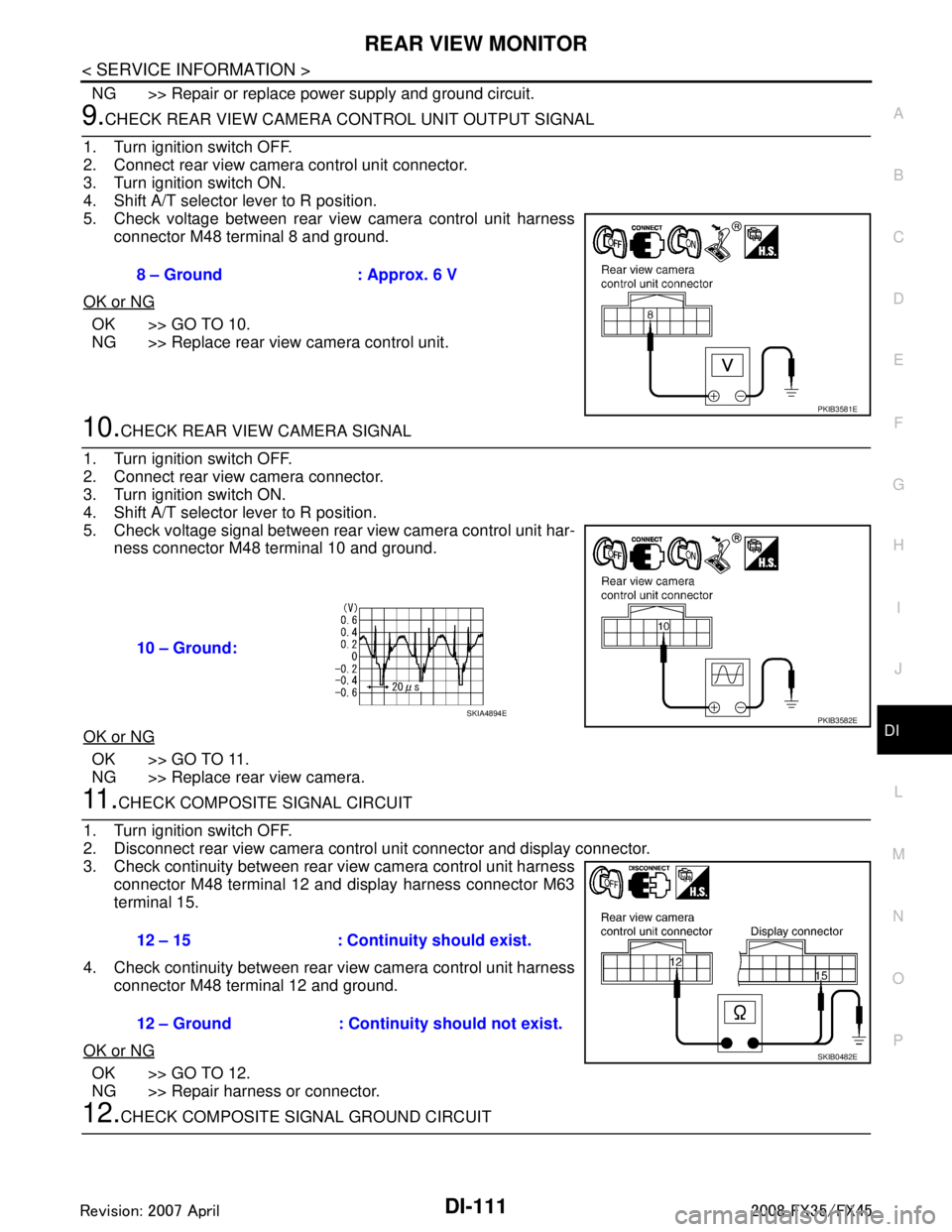
9.CHECK REAR VIEW CAMERA CONTROL UNIT OUTPUT SIGNAL
1. Turn ignition switch OFF.
2. Connect rear view camera control unit connector.
3. Turn ignition switch ON.
4. Shift A/T selector lever to R position.
5. Check voltage between rear view camera control unit harness connector M48 terminal 8 and ground.
OK or NG
OK >> GO TO 10.
NG >> Replace rear view camera control unit.
10.CHECK REAR VIEW CAMERA SIGNAL
1. Turn ignition switch OFF.
2. Connect rear view camera connector.
3. Turn ignition switch ON.
4. Shift A/T selector lever to R position.
5. Check voltage signal between rear view camera control unit har- ness connector M48 terminal 10 and ground.
OK or NG
OK >> GO TO 11.
NG >> Replace rear view camera.
11 .CHECK COMPOSITE SIGNAL CIRCUIT
1. Turn ignition switch OFF.
2. Disconnect rear view camera control unit connector and display connector.
3. Check continuity between rear view camera control unit harness connector M48 terminal 12 and display harness connector M63
terminal 15.
4. Check continuity between rear view camera control unit harness connector M48 terminal 12 and ground.
OK or NG
OK >> GO TO 12.
NG >> Repair harness or connector.
12.CHECK COMPOSITE SI GNAL GROUND CIRCUIT
8 – Ground : Approx. 6 V
PKIB3581E
10 – Ground:
PKIB3582ESKIA4894E
12 – 15 : Continuity should exist.
12 – Ground : Continuity should not exist.
SKIB0482E
3AA93ABC3ACD3AC03ACA3AC03AC63AC53A913A773A893A873A873A8E3A773A983AC73AC93AC03AC3
3A893A873A873A8F3A773A9D3AAF3A8A3A8C3A863A9D3AAF3A8B3A8C
Page 1242 of 3924

EC-2
Circuit Diagram ......................................................107
ECM Harness Connector Terminal Layout ............109
ECM Terminal and Reference Value .....................109
CONSULT-III Function (ENGINE) .........................117
Generic Scan Tool (GST) Function .......................125
CONSULT-III Reference Value in Data Monitor
Mode .................................................................... ..
127
TROUBLE DIAGNOSIS - SPECIFICATION
VALUE .............................................................
131
Description ........................................................... ..131
Testing Condition ...................................................131
Inspection Procedure .............................................131
Diagnosis Procedure .............................................131
TROUBLE DIAGNOSIS FOR INTERMITTENT
INCIDENT ........................................................
139
Description ........................................................... ..139
Diagnosis Procedure .............................................139
POWER SUPPLY AND GROUND CIRCUIT ...140
Wiring Diagram .................................................... ..140
Diagnosis Procedure .............................................141
Ground Inspection .................................................144
DTC U1000, U1001 CAN COMMUNICATION
LINE .................................................................
146
Description ........................................................... ..146
On Board Diagnosis Logic .....................................146
DTC Confirmation Procedure ................................146
Wiring Diagram ......................................................147
Diagnosis Procedure .............................................147
DTC U1010 CAN COMMUNICATION .............148
Description ........................................................... ..148
On Board Diagnosis Logic .....................................148
DTC Confirmation Procedure ................................148
Diagnosis Procedure .............................................148
DTC P0011, P0021 IVT CONTROL .................149
Description ........................................................... ..149
CONSULT-III Reference Value in Data Monitor
Mode .................................................................... ..
149
On Board Diagnosis Logic .....................................150
DTC Confirmation Procedure ................................150
Diagnosis Procedure .............................................151
Component Inspection ...........................................152
Removal and Installation .......................................152
DTC P0031, P0032, P0051, P0052 A/F SEN-
SOR 1 HEATER ...............................................
153
Description ........................................................... ..153
CONSULT-III Reference Value in Data Monitor
Mode .................................................................... ..
153
On Board Diagnosis Logic .....................................153
DTC Confirmation Procedure ................................153
Wiring Diagram ......................................................154
Diagnosis Procedure .............................................157
Component Inspection ...........................................158
Removal and Installation .......................................159
DTC P0037, P0038, P0057, P0058 HO2S2
HEATER ...........................................................
160
Description ........................................................... .160
CONSULT-III Reference Value in Data Monitor
Mode .....................................................................
160
On Board Diagnosis Logic ....................................160
DTC Confirmation Procedure ................................160
Wiring Diagram .....................................................162
Diagnosis Procedure .............................................165
Component Inspection ..........................................166
Removal and Installation .......................................167
DTC P0075, P0081 IVT CONTROL SOLE-
NOID VALVE ....................................................
168
Component Description ....................................... .168
CONSULT-III Reference Value in Data Monitor
Mode .....................................................................
168
On Board Diagnosis Logic ....................................168
DTC Confirmation Procedure ................................168
Wiring Diagram .....................................................169
Diagnosis Procedure .............................................172
Component Inspection ..........................................173
Removal and Installation .......................................174
DTC P0101 MAF SENSOR ..............................175
Component Description ....................................... .175
CONSULT-III Reference Value in Data Monitor
Mode .....................................................................
175
On Board Diagnosis Logic ....................................175
DTC Confirmation Procedure ................................175
Overall Function Check .........................................176
Wiring Diagram .....................................................177
Diagnosis Procedure .............................................178
Component Inspection ..........................................180
Removal and Installation .......................................181
DTC P0102, P0103 MAF SENSOR ..................182
Component Description ....................................... .182
CONSULT-III Reference Value in Data Monitor
Mode .....................................................................
182
On Board Diagnosis Logic ....................................182
DTC Confirmation Procedure ................................182
Wiring Diagram .....................................................184
Diagnosis Procedure .............................................185
Component Inspection ..........................................187
Removal and Installation .......................................188
DTC P0112, P0113 IAT SENSOR ....................189
Component Description ....................................... .189
On Board Diagnosis Logic ....................................189
DTC Confirmation Procedure ................................189
Wiring Diagram .....................................................190
Diagnosis Procedure .............................................190
Component Inspection ..........................................192
Removal and Installation .......................................192
DTC P0117, P0118 ECT SENSOR ...................193
Component Description ....................................... .193
On Board Diagnosis Logic ....................................193
DTC Confirmation Procedure ................................194
3AA93ABC3ACD3AC03ACA3AC03AC63AC53A913A773A893A873A873A8E3A773A983AC73AC93AC03AC3
3A893A873A873A8F3A773A9D3AAF3A8A3A8C3A863A9D3AAF3A8B3A8C
Page 1245 of 3924
EC-5
C
DE
F
G H
I
J
K L
M
EC A
N
O P
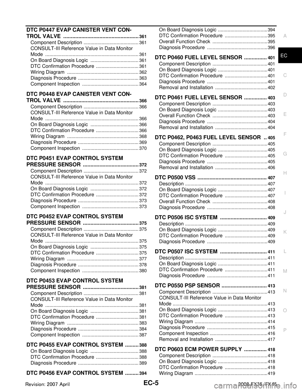
DTC P0447 EVAP CANISTER VENT CON-
TROL VALVE ................................................. ..
361
Component Description ....................................... ..361
CONSULT-III Reference Value in Data Monitor
Mode ................................................................... ..
361
On Board Diagnosis Logic ....................................361
DTC Confirmation Procedure ................................361
Wiring Diagram .....................................................362
Diagnosis Procedure .............................................363
Component Inspection ..........................................364
DTC P0448 EVAP CANISTER VENT CON-
TROL VALVE ...................................................
366
Component Description ....................................... ..366
CONSULT-III Reference Value in Data Monitor
Mode ................................................................... ..
366
On Board Diagnosis Logic ....................................366
DTC Confirmation Procedure ................................366
Wiring Diagram .....................................................368
Diagnosis Procedure .............................................369
Component Inspection ..........................................370
DTC P0451 EVAP CONTROL SYSTEM
PRESSURE SENSOR .................................... ..
372
Component Description ....................................... ..372
CONSULT-III Reference Value in Data Monitor
Mode ................................................................... ..
372
On Board Diagnosis Logic ....................................372
DTC Confirmation Procedure ................................372
Diagnosis Procedure .............................................373
Component Inspection ..........................................373
DTC P0452 EVAP CONTROL SYSTEM
PRESSURE SENSOR .................................... ..
375
Component Description ....................................... ..375
CONSULT-III Reference Value in Data Monitor
Mode ................................................................... ..
375
On Board Diagnosis Logic ....................................375
DTC Confirmation Procedure ................................375
Wiring Diagram .....................................................377
Diagnosis Procedure .............................................378
Component Inspection ..........................................380
DTC P0453 EVAP CONTROL SYSTEM
PRESSURE SENSOR .................................... ..
381
Component Description ....................................... ..381
CONSULT-III Reference Value in Data Monitor
Mode ................................................................... ..
381
On Board Diagnosis Logic ....................................381
DTC Confirmation Procedure ................................381
Wiring Diagram .....................................................383
Diagnosis Procedure .............................................384
Component Inspection ..........................................387
DTC P0455 EVAP CONTROL SYSTEM ..........388
On Board Diagnosis Logic .................................. ..388
DTC Confirmation Procedure ................................388
Diagnosis Procedure .............................................389
DTC P0456 EVAP CONTROL SYSTEM ..........394
On Board Diagnosis Logic ................................... ..394
DTC Confirmation Procedure ................................395
Overall Function Check .........................................395
Diagnosis Procedure .............................................396
DTC P0460 FUEL LEVEL SENSOR ...............401
Component Description .........................................401
On Board Diagnosis Logic .....................................401
DTC Confirmation Procedure ................................401
Diagnosis Procedure .............................................401
Removal and Installation .......................................402
DTC P0461 FUEL LEVEL SENSOR ...............403
Component Description .........................................403
On Board Diagnosis Logic .....................................403
Overall Function Check .........................................403
Diagnosis Procedure .............................................404
Removal and Installation .......................................404
DTC P0462, P0463 FUEL LEVEL SENSOR ..405
Component Description .........................................405
On Board Diagnosis Logic .....................................405
DTC Confirmation Procedure ................................405
Diagnosis Procedure .............................................405
Removal and Installation .......................................406
DTC P0500 VSS ..............................................407
Description .............................................................407
On Board Diagnosis Logic .....................................407
DTC Confirmation Procedure ................................407
Overall Function Check .........................................408
Diagnosis Procedure .............................................408
DTC P0506 ISC SYSTEM ...............................409
Description .............................................................409
On Board Diagnosis Logic .....................................409
DTC Confirmation Procedure ................................409
Diagnosis Procedure .............................................409
DTC P0507 ISC SYSTEM ...............................411
Description .............................................................411
On Board Diagnosis Logic .....................................411
DTC Confirmation Procedure ................................411
Diagnosis Procedure .............................................411
DTC P0550 PSP SENSOR ..............................413
Component Description .........................................413
CONSULT-III Reference Value in Data Monitor
Mode ......................................................................
413
On Board Diagnosis Logic .....................................413
DTC Confirmation Procedure ................................413
Wiring Diagram ......................................................414
Diagnosis Procedure .............................................415
Component Inspection ...........................................416
Removal and Installation .......................................417
DTC P0603 ECM POWER SUPPLY ...............418
Component Description .........................................418
On Board Diagnosis Logic .....................................418
DTC Confirmation Procedure ................................418
Wiring Diagram ......................................................419
3AA93ABC3ACD3AC03ACA3AC03AC63AC53A913A773A893A873A873A8E3A773A983AC73AC93AC03AC3
3A893A873A873A8F3A773A9D3AAF3A8A3A8C3A863A9D3AAF3A8B3A8C
Page 1246 of 3924

EC-6
Diagnosis Procedure .............................................420
DTC P0605 ECM ..............................................422
Component Description ....................................... ..422
On Board Diagnosis Logic .....................................422
DTC Confirmation Procedure ................................422
Diagnosis Procedure .............................................423
DTC P0643 SENSOR POWER SUPPLY ........424
On Board Diagnosis Logic ................................... ..424
DTC Confirmation Procedure ................................424
Wiring Diagram ......................................................425
Diagnosis Procedure .............................................426
DTC P0850 PNP SWITCH ...............................429
Component Description ....................................... ..429
CONSULT-III Reference Value in Data Monitor
Mode .................................................................... ..
429
On Board Diagnosis Logic .....................................429
DTC Confirmation Procedure ................................429
Overall Function Check .........................................430
Wiring Diagram ......................................................431
Diagnosis Procedure .............................................432
DTC P1148, P1168 CLOSED LOOP CON-
TROL ................................................................
434
On Board Diagnosis Logic ................................... ..434
DTC P1211 TCS CONTROL UNIT ..................435
Description ........................................................... ..435
On Board Diagnosis Logic .....................................435
DTC Confirmation Procedure ................................435
Diagnosis Procedure .............................................435
DTC P1212 TCS COMMUNICATION LINE .....436
Description ........................................................... ..436
On Board Diagnosis Logic .....................................436
DTC Confirmation Procedure ................................436
Diagnosis Procedure .............................................436
DTC P1217 ENGINE OVER TEMPERATURE .437
Description ........................................................... ..437
CONSULT-III Reference Value in Data Monitor
Mode .................................................................... ..
438
On Board Diagnosis Logic .....................................438
Overall Function Check .........................................439
Wiring Diagram ......................................................440
Diagnosis Procedure .............................................441
Main 12 Causes of Overheating ............................445
Component Inspection ...........................................446
DTC P1225 TP SENSOR .................................447
Component Description ....................................... ..447
On Board Diagnosis Logic .....................................447
DTC Confirmation Procedure ................................447
Diagnosis Procedure .............................................447
Removal and Installation .......................................448
DTC P1226 TP SENSOR .................................449
Component Description ....................................... ..449
On Board Diagnosis Logic .....................................449
DTC Confirmation Procedure ............................... .449
Diagnosis Procedure .............................................449
Removal and Installation .......................................450
DTC P1421 COLD START CONTROL ............451
Description ........................................................... .451
On Board Diagnosis Logic ....................................451
DTC Confirmation Procedure ................................451
Diagnosis Procedure .............................................451
DTC P1564 ICC STEERING SWITCH ..............453
Component Description ....................................... .453
CONSULT-III Reference Value in Data Monitor
Mode .....................................................................
453
On Board Diagnosis Logic ....................................453
DTC Confirmation Procedure ................................453
Wiring Diagram .....................................................455
Diagnosis Procedure .............................................456
Component Inspection ..........................................458
DTC P1564 ASCD STEERING SWITCH ..........459
Component Description ....................................... .459
CONSULT-III Reference Value in Data Monitor
Mode .....................................................................
459
On Board Diagnosis Logic ....................................459
DTC Confirmation Procedure ................................459
Wiring Diagram .....................................................460
Diagnosis Procedure .............................................461
Component Inspection ..........................................463
DTC P1568 ICC FUNCTION .............................464
On Board Diagnosis Logic ................................... .464
DTC Confirmation Procedure ................................464
Diagnosis Procedure .............................................464
DTC P1572 ICC BRAKE SWITCH ...................465
Component Description ....................................... .465
CONSULT-III Reference Value in Data Monitor
Mode .....................................................................
465
On Board Diagnosis Logic ....................................465
DTC Confirmation Procedure ................................465
Wiring Diagram .....................................................467
Diagnosis Procedure .............................................468
Component Inspection ..........................................472
DTC P1572 ASCD BRAKE SWITCH ...............474
Component Description ....................................... .474
CONSULT-III Reference Value in Data Monitor
Mode .....................................................................
474
On Board Diagnosis Logic ....................................474
DTC Confirmation Procedure ................................474
Wiring Diagram .....................................................476
Diagnosis Procedure .............................................477
Component Inspection ..........................................480
DTC P1574 ICC VEHICLE SPEED SENSOR ..481
Component Description ........................................481
On Board Diagnosis Logic ....................................481
DTC Confirmation Procedure ................................481
Diagnosis Procedure .............................................481
3AA93ABC3ACD3AC03ACA3AC03AC63AC53A913A773A893A873A873A8E3A773A983AC73AC93AC03AC3
3A893A873A873A8F3A773A9D3AAF3A8A3A8C3A863A9D3AAF3A8B3A8C
Page 1249 of 3924

EC-9
C
DE
F
G H
I
J
K L
M
EC A
N
O P
Removal and Installation .....................................
..
622
How to Detect Fuel Vapor Leakage ......................622
ON BOARD REFUELING VAPOR RECOV-
ERY (ORVR) .....................................................
624
System Description ............................................. ..624
Diagnosis Procedure .............................................624
Component Inspection ..........................................626
POSITIVE CRANKCASE VENTILATION ........629
Description .......................................................... ..629
Component Inspection ..........................................629
IVIS (INFINITI VEHICLE IMMOBILIZER SYS-
TEM-NATS) ......................................................
631
Description .......................................................... ..631
ON BOARD DIAGNOSTIC (OBD) SYSTEM ....632
Introduction ......................................................... ..632
Two Trip Detection Logic ......................................632
Emission-related Diagnostic Information ...............633
Malfunction Indicator Lamp (MIL) ..........................649
OBD System Operation Chart ...............................652
BASIC SERVICE PROCEDURE ......................658
Basic Inspection .................................................. ..658
Idle Speed and Ignition Timing Check ..................661
Procedure After Replacing ECM ...........................662
VIN Registration ....................................................662
Accelerator Pedal Released Position Learning .....662
Throttle Valve Closed Position Learning ...............663
Idle Air Volume Learning .......................................663
Fuel Pressure Check .............................................665
TROUBLE DIAGNOSIS ...................................666
Trouble Diagnosis Introduction ........................... ..666
DTC Inspection Priority Chart ...............................670
Fail-Safe Chart ......................................................671
Symptom Matrix Chart ..........................................673
Engine Control Component Parts Location ...........677
Vacuum Hose Drawing .........................................684
Circuit Diagram .....................................................685
ECM Harness Connector Terminal Layout ...........687
ECM Terminal and Reference Value ....................687
CONSULT-III Function (ENGINE) .........................695
Generic Scan Tool (GST) Function .......................704
CONSULT-III Reference Value in Data Monitor
Mode ................................................................... ..
705
TROUBLE DIAGNOSIS - SPECIFICATION
VALUE ..............................................................
709
Description .......................................................... ..709
Testing Condition ..................................................709
Inspection Procedure ............................................709
Diagnosis Procedure .............................................710
TROUBLE DIAGNOSIS FOR INTERMITTENT
INCIDENT .........................................................
717
Description .......................................................... ..717
Diagnosis Procedure .............................................717
POWER SUPPLY AND GROUND CIRCUIT ..718
Wiring Diagram .................................................... ..718
Diagnosis Procedure .............................................719
Ground Inspection .................................................723
DTC U1000, U1001 CAN COMMUNICATION
LINE .................................................................
724
Description .............................................................724
On Board Diagnosis Logic .....................................724
DTC Confirmation Procedure ................................724
Wiring Diagram ......................................................725
Diagnosis Procedure .............................................725
DTC U1010 CAN COMMUNICATION .............726
Description .............................................................726
On Board Diagnosis Logic .....................................726
DTC Confirmation Procedure ................................726
Diagnosis Procedure .............................................726
DTC P0011, P0021 IVT CONTROL ................727
Description .............................................................727
CONSULT-III Reference Value in Data Monitor
Mode ......................................................................
728
On Board Diagnosis Logic .....................................728
DTC Confirmation Procedure ................................728
Wiring Diagram ......................................................730
Diagnosis Procedure .............................................733
Component Inspection ...........................................737
Removal and Installation .......................................738
DTC P0031, P0032, P0051, P0052 A/F SEN-
SOR 1 HEATER ..............................................
739
Description .............................................................739
CONSULT-III Reference Value in Data Monitor
Mode ......................................................................
739
On Board Diagnosis Logic .....................................739
DTC Confirmation Procedure ................................739
Wiring Diagram ......................................................740
Diagnosis Procedure .............................................743
Component Inspection ...........................................744
Removal and Installation .......................................745
DTC P0037, P0038, P0057, P0058 HO2S2
HEATER ..........................................................
746
Description .............................................................746
CONSULT-III Reference Value in Data Monitor
Mode ......................................................................
746
On Board Diagnosis Logic .....................................746
DTC Confirmation Procedure ................................746
Wiring Diagram ......................................................748
Diagnosis Procedure .............................................751
Component Inspection ...........................................752
Removal and Installation .......................................753
DTC P0075, P0081 IVT CONTROL SOLE-
NOID VALVE ...................................................
754
Component Description .........................................754
CONSULT-III Reference Value in Data Monitor
Mode ......................................................................
754
On Board Diagnosis Logic .....................................754
3AA93ABC3ACD3AC03ACA3AC03AC63AC53A913A773A893A873A873A8E3A773A983AC73AC93AC03AC3
3A893A873A873A8F3A773A9D3AAF3A8A3A8C3A863A9D3AAF3A8B3A8C