2008 INFINITI FX35 ESP
[x] Cancel search: ESPPage 3380 of 3924
PG-16
< SERVICE INFORMATION >
POWER SUPPLY ROUTING CIRCUIT
Fuse
INFOID:0000000001328867
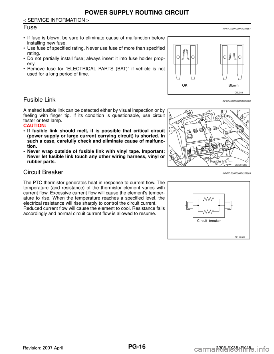
If fuse is blown, be sure to eliminate cause of malfunction before installing new fuse.
Use fuse of specified rating. Never use fuse of more than specified
rating.
Do not partially install fuse; always insert it into fuse holder prop- erly.
Remove fuse for “ELECTRICAL PARTS (BAT)” if vehicle is not used for a long period of time.
Fusible LinkINFOID:0000000001328868
A melted fusible link can be detected either by visual inspection or by
feeling with finger tip. If its condition is questionable, use circuit
tester or test lamp.
CAUTION:
• If fusible link should melt, it is possible that critical circuit
(power supply or large current carrying circuit) is shorted. In
such a case, carefully check an d eliminate cause of malfunc-
tion.
Never wrap outside of fusible li nk with vinyl tape. Important:
Never let fusible link touch an y other wiring harness, vinyl or
rubber parts.
Circuit BreakerINFOID:0000000001328869
The PTC thermistor generates heat in response to current flow. The
temperature (and resistance) of the thermistor element varies with
current flow. Excessive current flow will cause the element's temper-
ature to rise. When the temperature reaches a specified level, the
electrical resistance will rise sharply to control the circuit current.
Reduced current flow will cause the element to cool. Resistance falls
accordingly and normal circuit current flow is allowed to resume.
CEL083
CKIM0195E
SEL109W
3AA93ABC3ACD3AC03ACA3AC03AC63AC53A913A773A893A873A873A8E3A773A983AC73AC93AC03AC3
3A893A873A873A8F3A773A9D3AAF3A8A3A8C3A863A9D3AAF3A8B3A8C
Page 3432 of 3924
PG-68
< SERVICE INFORMATION >
HARNESS CONNECTOR
HARNESS CONNECTOR
DescriptionINFOID:0000000001328885
HARNESS CONNECTOR (TAB-LOCKING TYPE)
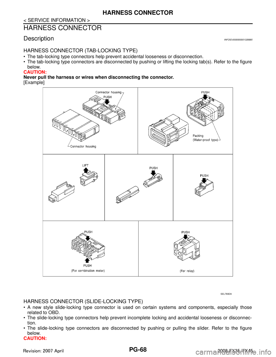
The tab-locking type connectors help prevent accidental looseness or disconnection.
The tab-locking type connectors are disconnected by pushing or lifting the locking tab(s). Refer to the figure
below.
CAUTION:
Never pull the harness or wires wh en disconnecting the connector.
[Example]
HARNESS CONNECTOR (SLIDE-LOCKING TYPE)
A new style slide-locking type connector is used on certain systems and components, especially those
related to OBD.
The slide-locking type connectors help prevent incomplete locking and accidental looseness or disconnec-
tion.
The slide-locking type connectors are disconnected by pushing or pulling the slider. Refer to the figure below.
CAUTION:
SEL769DA
3AA93ABC3ACD3AC03ACA3AC03AC63AC53A913A773A893A873A873A8E3A773A983AC73AC93AC03AC3
3A893A873A873A8F3A773A9D3AAF3A8A3A8C3A863A9D3AAF3A8B3A8C
Page 3477 of 3924
PS-22
< SERVICE INFORMATION >
POWER STEERING GEAR AND LINKAGE
Gear Housing Assembly
Check gear housing assembly for damage and scratches (inner wall). Replace it, if necessary.
Outer Socket and Inner Socket
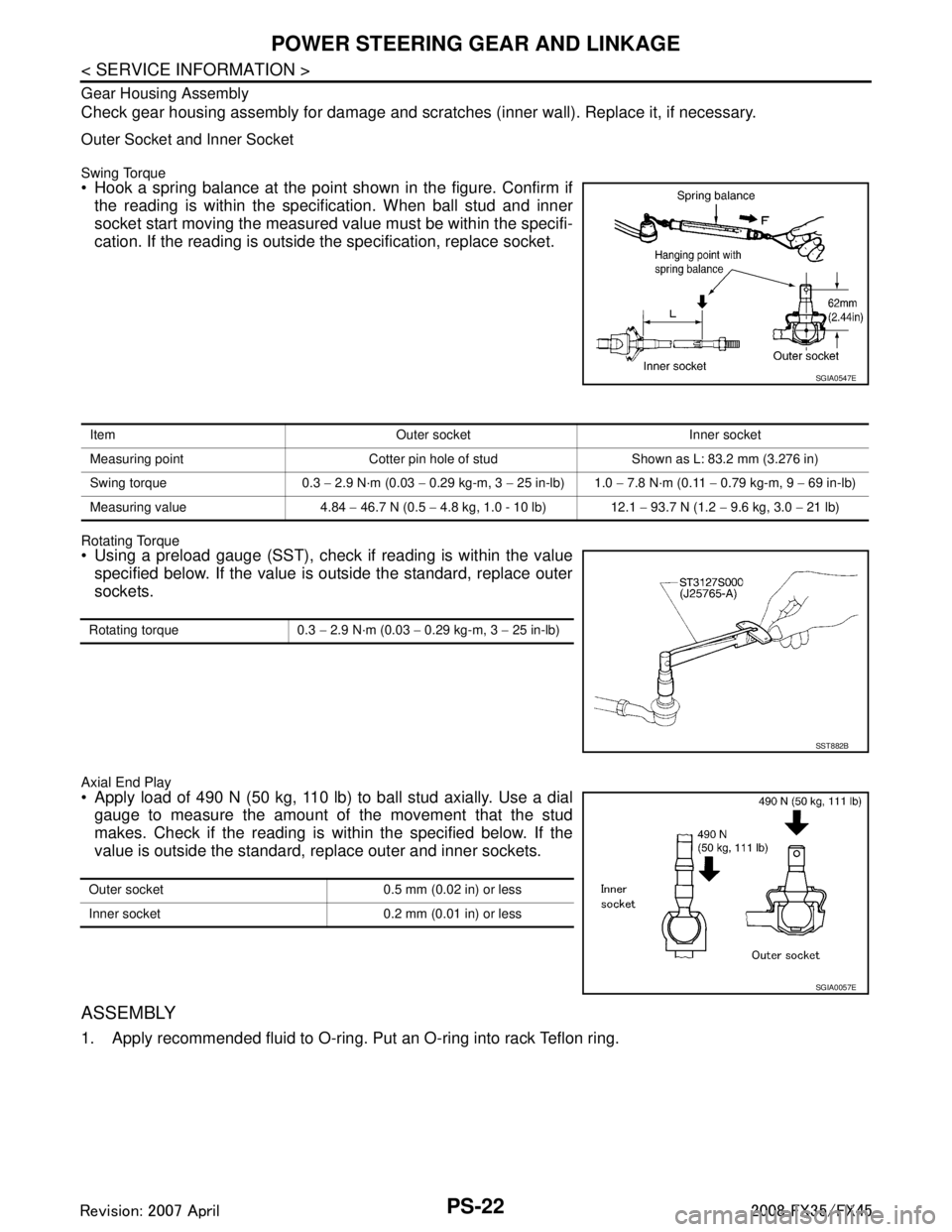
Swing Torque Hook a spring balance at the point shown in the figure. Confirm ifthe reading is within the specification. When ball stud and inner
socket start moving the measured value must be within the specifi-
cation. If the reading is outside the specification, replace socket.
Rotating Torque Using a preload gauge (SST), check if reading is within the valuespecified below. If the value is outside the standard, replace outer
sockets.
Axial End Play Apply load of 490 N (50 kg, 110 lb) to ball stud axially. Use a dialgauge to measure the amount of the movement that the stud
makes. Check if the reading is within the specified below. If the
value is outside the standard, replace outer and inner sockets.
ASSEMBLY
1. Apply recommended fluid to O-ring. Put an O-ring into rack Teflon ring.
SGIA0547E
Item Outer socket Inner socket
Measuring point Cotter pin hole of stud Shown as L: 83.2 mm (3.276 in)
Swing torque 0.3 − 2.9 N·m (0.03 − 0.29 kg-m, 3 − 25 in-lb) 1.0 − 7.8 N·m (0.11 − 0.79 kg-m, 9 − 69 in-lb)
Measuring value 4.84 − 46.7 N (0.5 − 4.8 kg, 1.0 - 10 lb) 12.1 − 93.7 N (1.2 − 9.6 kg, 3.0 − 21 lb)
Rotating torque 0.3 − 2.9 N·m (0.03 − 0.29 kg-m, 3 − 25 in-lb)
SST882B
Outer socket 0.5 mm (0.02 in) or less
Inner socket 0.2 mm (0.01 in) or less
SGIA0057E
3AA93ABC3ACD3AC03ACA3AC03AC63AC53A913A773A893A873A873A8E3A773A983AC73AC93AC03AC3
3A893A873A873A8F3A773A9D3AAF3A8A3A8C3A863A9D3AAF3A8B3A8C
Page 3519 of 3924
RF-4
< SERVICE INFORMATION >
SQUEAK AND RATTLE TROUBLE DIAGNOSES
SQUEAK AND RATTLE TROUBLE DIAGNOSES
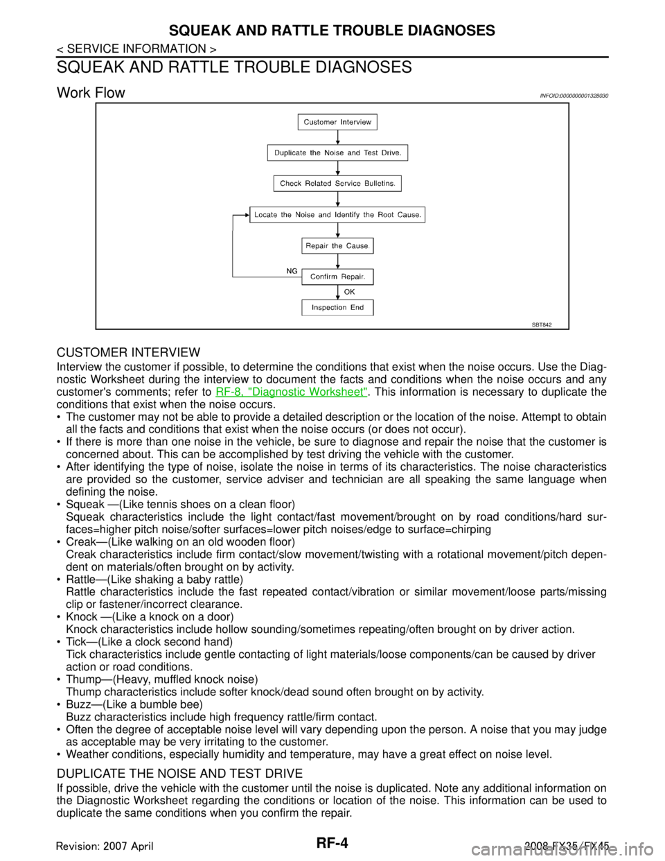
Work FlowINFOID:0000000001328030
CUSTOMER INTERVIEW
Interview the customer if possible, to determine the c onditions that exist when the noise occurs. Use the Diag-
nostic Worksheet during the interview to document the facts and conditions when the noise occurs and any
customer's comments; refer to RF-8, "
Diagnostic Worksheet". This information is necessary to duplicate the
conditions that exist when the noise occurs.
The customer may not be able to provide a detailed description or the location of the noise. Attempt to obtain all the facts and conditions that exist w hen the noise occurs (or does not occur).
If there is more than one noise in the vehicle, be sure to diagnose and repair the noise that the customer is
concerned about. This can be accomplished by test driving the vehicle with the customer.
After identifying the type of noise, isolate the noise in terms of its characteristics. The noise characteristics
are provided so the customer, service adviser and technician are all speaking the same language when
defining the noise.
Squeak —(Like tennis shoes on a clean floor)
Squeak characteristics include the light contact/fa st movement/brought on by road conditions/hard sur-
faces=higher pitch noise/softer surfaces=l ower pitch noises/edge to surface=chirping
Creak—(Like walking on an old wooden floor)
Creak characteristics include firm contact/slow mo vement/twisting with a rotational movement/pitch depen-
dent on materials/often brought on by activity.
Rattle—(Like shaking a baby rattle)
Rattle characteristics include the fast repeated contac t/vibration or similar movement/loose parts/missing
clip or fastener/incorrect clearance.
Knock —(Like a knock on a door)
Knock characteristics include hollow sounding/someti mes repeating/often brought on by driver action.
Tick—(Like a clock second hand) Tick characteristics include gentle contacting of light materials/loose components/can be caused by driver
action or road conditions.
Thump—(Heavy, muffled knock noise) Thump characteristics include softer k nock/dead sound often brought on by activity.
Buzz—(Like a bumble bee)
Buzz characteristics include hi gh frequency rattle/firm contact.
Often the degree of acceptable noise level will vary depending upon the person. A noise that you may judge as acceptable may be very irritating to the customer.
Weather conditions, especially humidity and temperat ure, may have a great effect on noise level.
DUPLICATE THE NOISE AND TEST DRIVE
If possible, drive the vehicle with the customer until the noise is duplicated. Note any additional information on
the Diagnostic Worksheet regarding the conditions or lo cation of the noise. This information can be used to
duplicate the same conditions when you confirm the repair.
SBT842
3AA93ABC3ACD3AC03ACA3AC03AC63AC53A913A773A893A873A873A8E3A773A983AC73AC93AC03AC3
3A893A873A873A8F3A773A9D3AAF3A8A3A8C3A863A9D3AAF3A8B3A8C
Page 3645 of 3924
SE-6
< SERVICE INFORMATION >
SQUEAK AND RATTLE TROUBLE DIAGNOSES
SQUEAK AND RATTLE TROUBLE DIAGNOSES
Work FlowINFOID:0000000001328094
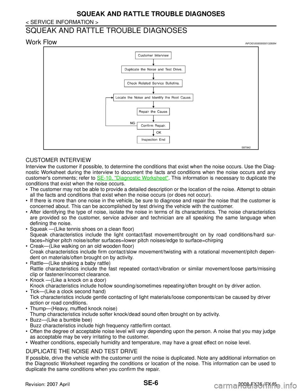
CUSTOMER INTERVIEW
Interview the customer if possible, to determine the c onditions that exist when the noise occurs. Use the Diag-
nostic Worksheet during the interview to document the facts and conditions when the noise occurs and any
customer's comments; refer to SE-10, "
Diagnostic Worksheet". This information is necessary to duplicate the
conditions that exist when the noise occurs.
The customer may not be able to provide a detailed description or the location of the noise. Attempt to obtain all the facts and conditions that exist w hen the noise occurs (or does not occur).
If there is more than one noise in the vehicle, be sure to diagnose and repair the noise that the customer is
concerned about. This can be accomplished by test driving the vehicle with the customer.
After identifying the type of noise, isolate the noise in terms of its characteristics. The noise characteristics
are provided so the customer, service adviser and technician are all speaking the same language when
defining the noise.
Squeak —(Like tennis shoes on a clean floor)
Squeak characteristics include the light contact/fa st movement/brought on by road conditions/hard sur-
faces=higher pitch noise/softer surfaces=l ower pitch noises/edge to surface=chirping
Creak—(Like walking on an old wooden floor)
Creak characteristics include firm contact/slow mo vement/twisting with a rotational movement/pitch depen-
dent on materials/often brought on by activity.
Rattle—(Like shaking a baby rattle)
Rattle characteristics include the fast repeated contac t/vibration or similar movement/loose parts/missing
clip or fastener/incorrect clearance.
Knock —(Like a knock on a door)
Knock characteristics include hollow sounding/someti mes repeating/often brought on by driver action.
Tick—(Like a clock second hand) Tick characteristics include gentle contacting of light materials/loose components/can be caused by driver
action or road conditions.
Thump—(Heavy, muffled knock noise) Thump characteristics include softer k nock/dead sound often brought on by activity.
Buzz—(Like a bumble bee)
Buzz characteristics include hi gh frequency rattle/firm contact.
Often the degree of acceptable noise level will vary depending upon the person. A noise that you may judge as acceptable may be very irritating to the customer.
Weather conditions, especially humidity and temperat ure, may have a great effect on noise level.
DUPLICATE THE NOISE AND TEST DRIVE
If possible, drive the vehicle with the customer until the noise is duplicated. Note any additional information on
the Diagnostic Worksheet regarding the conditions or lo cation of the noise. This information can be used to
duplicate the same conditions when you confirm the repair.
SBT842
3AA93ABC3ACD3AC03ACA3AC03AC63AC53A913A773A893A873A873A8E3A773A983AC73AC93AC03AC3
3A893A873A873A8F3A773A9D3AAF3A8A3A8C3A863A9D3AAF3A8B3A8C
Page 3797 of 3924
AWD SYSTEMTF-11
< SERVICE INFORMATION >
CEF
G H
I
J
K L
M A
B
TF
N
O P
AWD SYSTEM
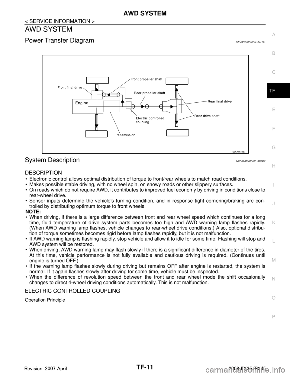
Power Transfer DiagramINFOID:0000000001327431
System DescriptionINFOID:0000000001327432
DESCRIPTION
Electronic control allows optimal distribution of torque to front/rear wheels to match road conditions.
Makes possible stable driving, with no wheel sp in, on snowy roads or other slippery surfaces.
On roads which do not require AWD, it contributes to improved fuel economy by driving in conditions close to
rear-wheel drive.
Sensor inputs determine the vehicle's turning conditi on, and in response tight cornering/braking are con-
trolled by distributing optimum torque to front wheels.
NOTE:
When driving, if there is a large difference between front and rear wheel speed which continues for a long
time, fluid temperature of drive system parts becom es too high and AWD warning lamp flashes rapidly.
(When AWD warning lamp flashes, vehicle changes to r ear-wheel drive conditions.) Also, optional distribu-
tion of torque sometimes becomes rigid before lamp flashes rapidly, but it is not malfunction.
If AWD warning lamp is flashing rapidly, stop vehicle and allow it to idle for some time. Flashing will stop and AWD system will be restored.
When driving, AWD warning lamp may flash slowly if ther e is a significant difference in diameter of the tires.
At this time, vehicle performance is not fully avail able and cautious driving is required. (Continues until
engine is turned OFF.)
If the warning lamp flashes slowly during driving but remains OFF after engine is restarted, the system is
normal. If it again flashes slowly after driving for some time, vehicle must be inspected.
When the difference of revolution speed between the front and rear wheel mode the shift occasionally
changes to direct 4-wheel driving conditions automatically. This is not malfunction.
ELECTRIC CONTROLLED COUPLING
Operation Principle
SDIA1611E
3AA93ABC3ACD3AC03ACA3AC03AC63AC53A913A773A893A873A873A8E3A773A983AC73AC93AC03AC3
3A893A873A873A8F3A773A9D3AAF3A8A3A8C3A863A9D3AAF3A8B3A8C
Page 3798 of 3924
TF-12
< SERVICE INFORMATION >
AWD SYSTEM
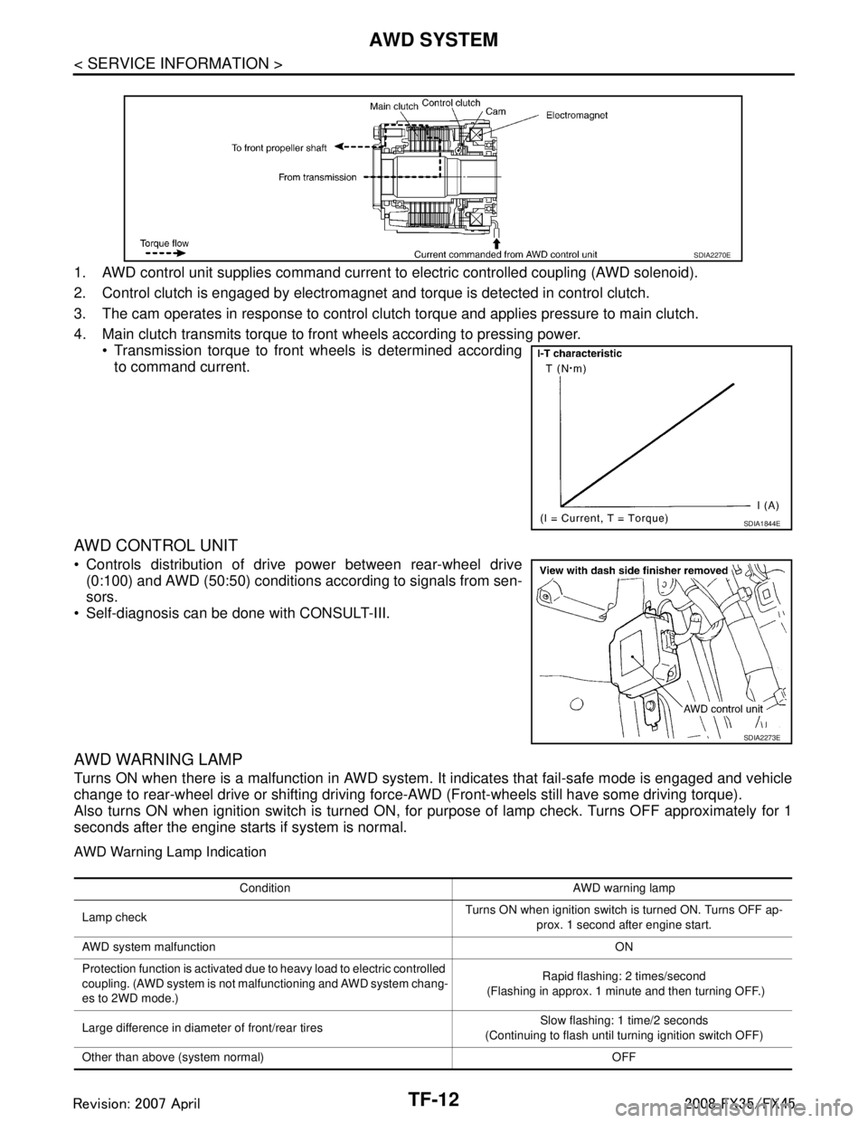
1. AWD control unit supplies command current to electric controlled coupling (AWD solenoid).
2. Control clutch is engaged by electromagnet and torque is detected in control clutch.
3. The cam operates in response to control clutch torque and applies pressure to main clutch.
4. Main clutch transmits torque to front wheels according to pressing power. Transmission torque to front wheels is determined accordingto command current.
AWD CONTROL UNIT
Controls distribution of drive power between rear-wheel drive(0:100) and AWD (50:50) conditions according to signals from sen-
sors.
Self-diagnosis can be done with CONSULT-III.
AWD WARNING LAMP
Turns ON when there is a malfunction in AWD system. It indicates that fail-safe mode is engaged and vehicle
change to rear-wheel drive or shifting driving force- AWD (Front-wheels still have some driving torque).
Also turns ON when ignition switch is turned ON, for purpose of lamp check. Turns OFF approximately for 1
seconds after the engine starts if system is normal.
AWD Warning Lamp Indication
SDIA2270E
SDIA1844E
SDIA2273E
Condition AWD warning lamp
Lamp check Turns ON when ignition switch is turned ON. Turns OFF ap-
prox. 1 second after engine start.
AWD system malfunction ON
Protection function is activated due to heavy load to electric controlled
coupling. (AWD system is not malfunctioning and AWD system chang-
es to 2WD mode.) Rapid flashing: 2 times/second
(Flashing in approx. 1 minute and then turning OFF.)
Large difference in diameter of front/rear tires Slow flashing: 1 time/2 seconds
(Continuing to flash until turning ignition switch OFF)
Other than above (system normal) OFF
3AA93ABC3ACD3AC03ACA3AC03AC63AC53A913A773A893A873A873A8E3A773A983AC73AC93AC03AC3
3A893A873A873A8F3A773A9D3AAF3A8A3A8C3A863A9D3AAF3A8B3A8C
Page 3807 of 3924
TROUBLE DIAGNOSISTF-21
< SERVICE INFORMATION >
CEF
G H
I
J
K L
M A
B
TF
N
O P
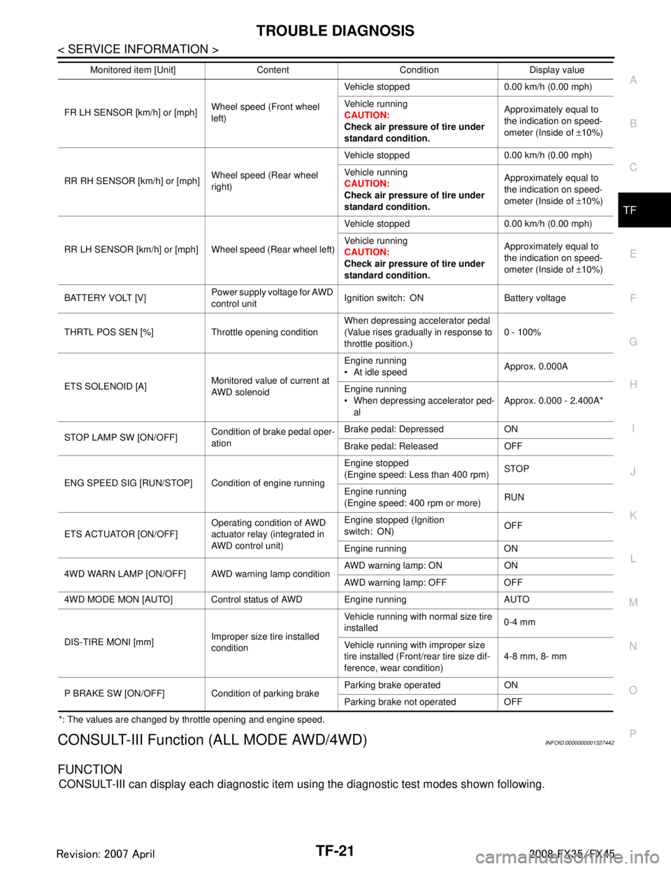
*: The values are changed by throttle opening and engine speed.
CONSULT-III Function (ALL MODE AWD/4WD)INFOID:0000000001327442
FUNCTION
CONSULT-III can display each diagnostic item using the diagnostic test modes shown following.
FR LH SENSOR [km/h] or [mph] Wheel speed (Front wheel
left)Vehicle stopped 0.00 km/h (0.00 mph)
Vehicle running
CAUTION:
Check air pressure of tire under
standard condition.
Approximately equal to
the indication on speed-
ometer (Inside of
±10%)
RR RH SENSOR [km/h] or [mph] Wheel speed (Rear wheel
right)Vehicle stopped 0.00 km/h (0.00 mph)
Vehicle running
CAUTION:
Check air pressure of tire under
standard condition.
Approximately equal to
the indication on speed-
ometer (Inside of
±10%)
RR LH SENSOR [km/h] or [mph] Wheel speed (Rear wheel left) Vehicle stopped 0.00 km/h (0.00 mph)
Vehicle running
CAUTION:
Check air pressure of tire under
standard condition.Approximately equal to
the indication on speed-
ometer (Inside of
±10%)
BATTERY VOLT [V] Power supply voltage for AWD
control unitIgnition switch: ON Battery voltage
THRTL POS SEN [%] Throttle opening condition When depressing accelerator pedal
(Value rises gradually in response to
throttle position.)0 - 100%
ETS SOLENOID [A] Monitored value of current at
AWD solenoidEngine running
At idle speed
Approx. 0.000A
Engine running
When depressing accelerator ped- al Approx. 0.000 - 2.400A*
STOP LAMP SW [ON/OFF] Condition of brake pedal oper-
ationBrake pedal: Depressed ON
Brake pedal: Released OFF
ENG SPEED SIG [RUN/STOP] Condi tion of engine runningEngine stopped
(Engine speed: Less than 400 rpm)
STOP
Engine running
(Engine speed: 400 rpm or more) RUN
ETS ACTUATOR [ON/OFF] Operating condition of AWD
actuator relay (integrated in
AWD control unit)Engine stopped (Ignition
switch: ON)
OFF
Engine running ON
4WD WARN LAMP [ON/OFF] AWD warning lamp conditionAWD warning lamp: ON ON
AWD warning lamp: OFF OFF
4WD MODE MON [AUTO] Control status of AWD Engine running AUTO
DIS-TIRE MONI [mm] Improper size tire installed
conditionVehicle running with normal size tire
installed
0-4 mm
Vehicle running with improper size
tire installed (Front /rear tire size dif-
ference, wear condition) 4-8 mm, 8- mm
P BRAKE SW [ON/OFF] Condition of parking brake Parking brake operated ON
Parking brake not operated OFF
Monitored item [Unit] Content Condition Display value
3AA93ABC3ACD3AC03ACA3AC03AC63AC53A913A773A893A873A873A8E3A773A983AC73AC93AC03AC3
3A893A873A873A8F3A773A9D3AAF3A8A3A8C3A863A9D3AAF3A8B3A8C