2008 INFINITI FX35 ESP
[x] Cancel search: ESPPage 2865 of 3924
PRECAUTIONSGI-3
< SERVICE INFORMATION >
C
DE
F
G H
I
J
K L
M B
GI
N
O P
Precaution for Procedur e without Cowl Top CoverINFOID:0000000001612933
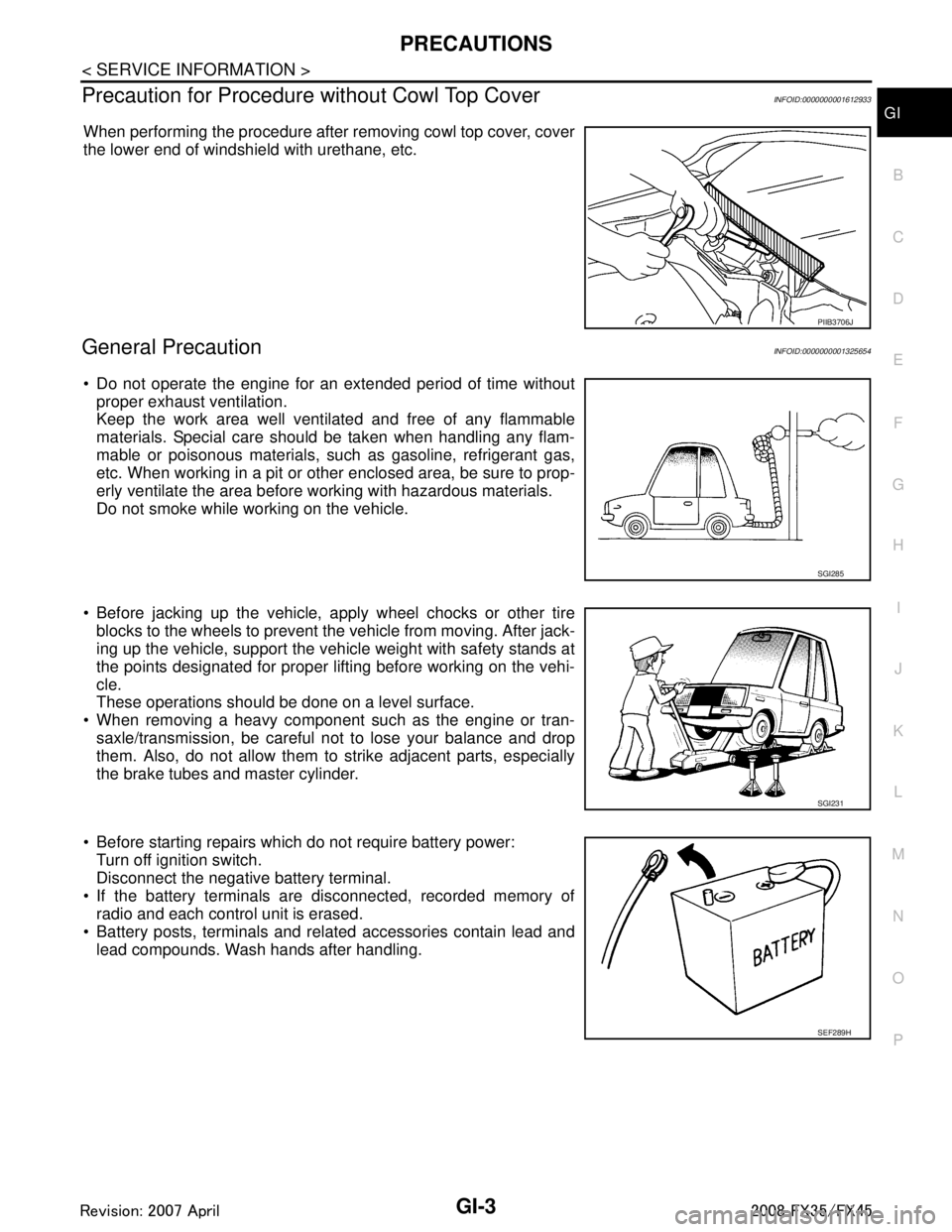
When performing the procedure after removing cowl top cover, cover
the lower end of windshield with urethane, etc.
General PrecautionINFOID:0000000001325654
Do not operate the engine for an extended period of time without
proper exhaust ventilation.
Keep the work area well ventilated and free of any flammable
materials. Special care should be taken when handling any flam-
mable or poisonous materials, such as gasoline, refrigerant gas,
etc. When working in a pit or ot her enclosed area, be sure to prop-
erly ventilate the area before working with hazardous materials.
Do not smoke while working on the vehicle.
Before jacking up the vehicle, apply wheel chocks or other tire
blocks to the wheels to prevent the vehicle from moving. After jack-
ing up the vehicle, support the vehicle weight with safety stands at
the points designated for proper lifting before working on the vehi-
cle.
These operations should be done on a level surface.
When removing a heavy component such as the engine or tran- saxle/transmission, be careful not to lose your balance and drop
them. Also, do not allow them to strike adjacent parts, especially
the brake tubes and master cylinder.
Before starting repairs which do not require battery power: Turn off ignition switch.
Disconnect the negative battery terminal.
If the battery terminals are disconnected, recorded memory of radio and each control unit is erased.
Battery posts, terminals and related accessories contain lead and
lead compounds. Wash hands after handling.
PIIB3706J
SGI285
SGI231
SEF289H
3AA93ABC3ACD3AC03ACA3AC03AC63AC53A913A773A893A873A873A8E3A773A983AC73AC93AC03AC3
3A893A873A873A8F3A773A9D3AAF3A8A3A8C3A863A9D3AAF3A8B3A8C
Page 2876 of 3924
GI-14
< SERVICE INFORMATION >
HOW TO USE THIS MANUAL
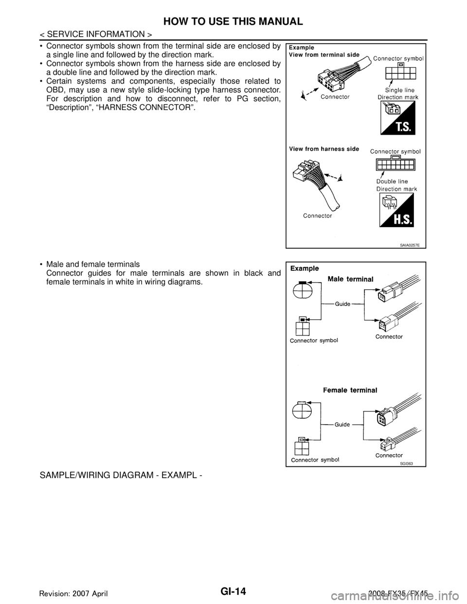
Connector symbols shown from the terminal side are enclosed bya single line and followed by the direction mark.
Connector symbols shown from the harness side are enclosed by
a double line and followed by the direction mark.
Certain systems and components, especially those related to OBD, may use a new style slide-locking type harness connector.
For description and how to disconnect, refer to PG section,
“Description”, “HARNESS CONNECTOR”.
Male and female terminals Connector guides for male terminals are shown in black and
female terminals in white in wiring diagrams.
SAMPLE/WIRING DIAGRAM - EXAMPL -
SAIA0257E
SGI363
3AA93ABC3ACD3AC03ACA3AC03AC63AC53A913A773A893A873A873A8E3A773A983AC73AC93AC03AC3
3A893A873A873A8F3A773A9D3AAF3A8A3A8C3A863A9D3AAF3A8B3A8C
Page 2879 of 3924
HOW TO USE THIS MANUALGI-17
< SERVICE INFORMATION >
C
DE
F
G H
I
J
K L
M B
GI
N
O P
Harness Indication
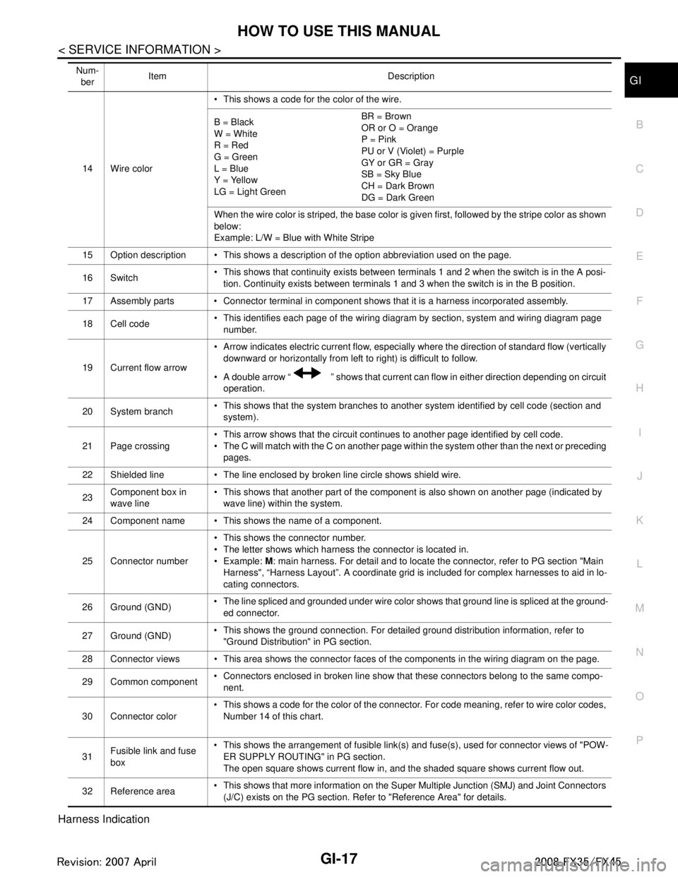
14 Wire color This shows a code for the color of the wire.
B = Black
W = White
R = Red
G = Green
L = Blue
Y = Yellow
LG = Light Green BR = Brown
OR or O = Orange
P = Pink
PU or V (Violet) = Purple
GY or GR = Gray
SB = Sky Blue
CH = Dark Brown
DG = Dark Green
When the wire color is striped, the base color is given first, followed by the stripe color as shown
below:
Example: L/W = Blue with White Stripe
15 Option description This shows a description of the option abbreviation used on the page.
16 Switch This shows that continuity exists between terminals 1 and 2 when the switch is in the A posi-
tion. Continuity exists between terminals 1 and 3 when the switch is in the B position.
17 Assembly parts Connector terminal in component shows that it is a harness incorporated assembly.
18 Cell code This identifies each page of the wiring diagram by section, system and wiring diagram page
number.
19 Current flow arrow Arrow indicates electric current flow, especially where the direction of standard flow (vertically
downward or horizontally from left to right) is difficult to follow.
A double arrow “ ” shows that current can flow in either direction depending on circuit operation.
20 System branch This shows that the system branches to another system identified by cell code (section and
system).
21 Page crossing This arrow shows that the circuit continues to another page identified by cell code.
The C will match with the C on another page within the system other than the next or preceding
pages.
22 Shielded line The line enclosed by broken line circle shows shield wire.
23 Component box in
wave line This shows that another part of the component is also shown on another page (indicated by
wave line) within the system.
24 Component name This shows the name of a component.
25 Connector number This shows the connector number.
The letter shows which harness the connector is located in.
Example:
M: main harness. For detail and to locate the connector, refer to PG section "Main
Harness", “Harness Layout”. A coordinate grid is included for complex harnesses to aid in lo-
cating connectors.
26 Ground (GND) The line spliced and grounded under wire color shows that ground line is spliced at the ground-
ed connector.
27 Ground (GND) This shows the ground connection. For detailed ground distribution information, refer to
"Ground Distribution" in PG section.
28 Connector views This area shows the connector faces of the components in the wiring diagram on the page.
29 Common component Connectors enclosed in broken line show that these connectors belong to the same compo-
nent.
30 Connector color This shows a code for the color of the connector. For code meaning, refer to wire color codes,
Number 14 of this chart.
31 Fusible link and fuse
box This shows the arrangement of fusible link(s) and fuse(s), used for connector views of "POW-
ER SUPPLY ROUTING" in PG section.
The open square shows current flow in, and the shaded square shows current flow out.
32 Reference area This shows that more information on the Super Multiple Junction (SMJ) and Joint Connectors
(J/C) exists on the PG section. Refer to "Reference Area" for details.
Num-
ber Item Description
3AA93ABC3ACD3AC03ACA3AC03AC63AC53A913A773A893A873A873A8E3A773A983AC73AC93AC03AC3
3A893A873A873A8F3A773A9D3AAF3A8A3A8C3A863A9D3AAF3A8B3A8C
Page 2918 of 3924
SQUEAK AND RATTLE TROUBLE DIAGNOSESGW-5
< SERVICE INFORMATION >
C
DE
F
G H
J
K L
M A
B
GW
N
O P
SQUEAK AND RATTLE TROUBLE DIAGNOSES
Work FlowINFOID:0000000001327957
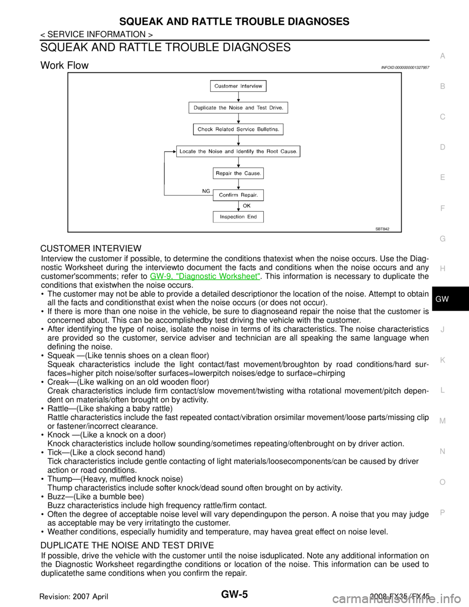
CUSTOMER INTERVIEW
Interview the customer if possible, to determine the conditions thatexist when the noise occurs. Use the Diag-
nostic Worksheet during the interviewto document t he facts and conditions when the noise occurs and any
customer'scomments; refer to GW-9, "
Diagnostic Worksheet". This information is necessary to duplicate the
conditions that existwhen the noise occurs.
The customer may not be able to provide a detailed descriptionor the location of the noise. Attempt to obtain all the facts and conditionsthat exist w hen the noise occurs (or does not occur).
If there is more than one noise in the vehicle, be sure to diagnoseand repair the noise that the customer is
concerned about. This can be accomplishedby test driving the vehicle with the customer.
After identifying the type of noise, isolate the noise in terms of its characteristics. The noise characteristics
are provided so the customer, service adviser and technician are all speaking the same language when
defining the noise.
Squeak —(Like tennis shoes on a clean floor)
Squeak characteristics include the light contact/fa st movement/broughton by road conditions/hard sur-
faces=higher pitch noise/softer surfaces=l owerpitch noises/edge to surface=chirping
Creak—(Like walking on an old wooden floor)
Creak characteristics include firm contact/slow mo vement/twisting witha rotational movement/pitch depen-
dent on materials/often brought on by activity.
Rattle—(Like shaking a baby rattle)
Rattle characteristics include the fast repeated contac t/vibration orsimilar movement/loose parts/missing clip
or fastener/incorrect clearance.
Knock —(Like a knock on a door)
Knock characteristics include hollow sounding/some times repeating/oftenbrought on by driver action.
Tick—(Like a clock second hand) Tick characteristics include gentle contacting of li ght materials/loosecomponents/can be caused by driver
action or road conditions.
Thump—(Heavy, muffled knock noise) Thump characteristics include softer k nock/dead sound often brought on by activity.
Buzz—(Like a bumble bee)
Buzz characteristics include high frequency rattle/firm contact.
Often the degree of acceptable noise level will vary dependingupon the person. A noise that you may judge as acceptable may be very irritatingto the customer.
Weather conditions, especially humidity and temper ature, may havea great effect on noise level.
DUPLICATE THE NOISE AND TEST DRIVE
If possible, drive the vehicle with the customer until the noise isduplicated. Note any additional information on
the Diagnostic Worksheet regardingthe conditions or location of the noise. This information can be used to
duplicatethe same conditions when you confirm the repair.
SBT842
3AA93ABC3ACD3AC03ACA3AC03AC63AC53A913A773A893A873A873A8E3A773A983AC73AC93AC03AC3
3A893A873A873A8F3A773A9D3AAF3A8A3A8C3A863A9D3AAF3A8B3A8C
Page 3005 of 3924
IP-4
< SERVICE INFORMATION >
SQUEAK AND RATTLE TROUBLE DIAGNOSES
SQUEAK AND RATTLE TROUBLE DIAGNOSES
Work FlowINFOID:0000000001328084
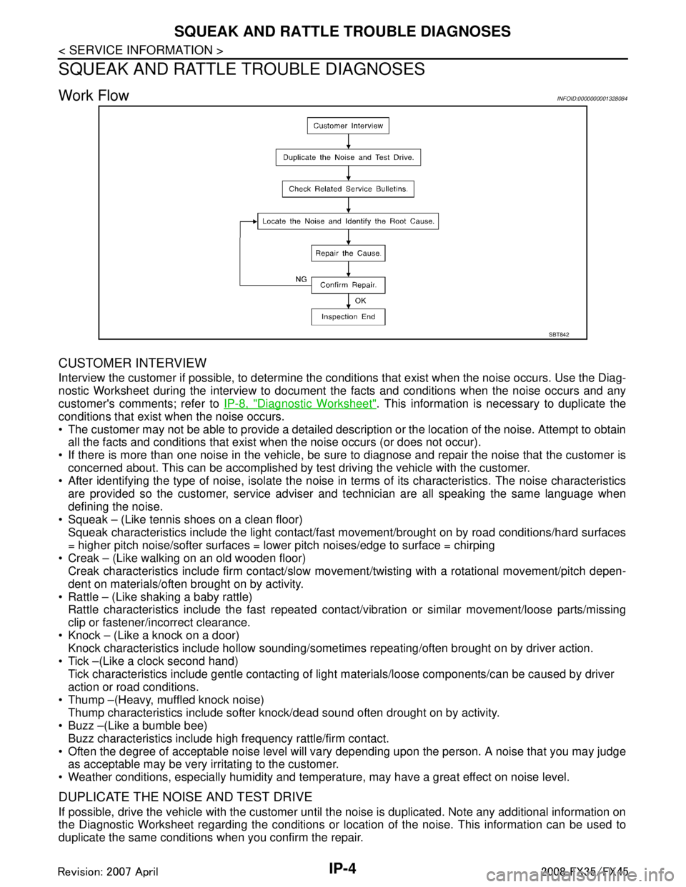
CUSTOMER INTERVIEW
Interview the customer if possible, to determine the c onditions that exist when the noise occurs. Use the Diag-
nostic Worksheet during the interview to document the facts and conditions when the noise occurs and any
customer's comments; refer to IP-8, "
Diagnostic Worksheet". This information is necessary to duplicate the
conditions that exist when the noise occurs.
The customer may not be able to provide a detailed description or the location of the noise. Attempt to obtain all the facts and conditions that exist w hen the noise occurs (or does not occur).
If there is more than one noise in the vehicle, be sure to diagnose and repair the noise that the customer is
concerned about. This can be accomplished by te st driving the vehicle with the customer.
After identifying the type of noise, isolate the noise in terms of its characteristics. The noise characteristics
are provided so the customer, service adviser and technician are all speaking the same language when
defining the noise.
Squeak – (Like tennis shoes on a clean floor)
Squeak characteristics include the light contact/fast movement/brought on by road conditions/hard surfaces
= higher pitch noise/softer surfaces = lower pitch noises/edge to surface = chirping
Creak – (Like walking on an old wooden floor)
Creak characteristics include firm contact/slow mo vement/twisting with a rotational movement/pitch depen-
dent on materials/often brought on by activity.
Rattle – (Like shaking a baby rattle)
Rattle characteristics include the fast repeated contac t/vibration or similar movement/loose parts/missing
clip or fastener/incorrect clearance.
Knock – (Like a knock on a door)
Knock characteristics include hollow sounding/someti mes repeating/often brought on by driver action.
Tick –(Like a clock second hand) Tick characteristics include gentle contacting of light materials/loose components/can be caused by driver
action or road conditions.
Thump –(Heavy, muffled knock noise) Thump characteristics include softer k nock/dead sound often drought on by activity.
Buzz –(Like a bumble bee)
Buzz characteristics include hi gh frequency rattle/firm contact.
Often the degree of acceptable noise level will vary depending upon the person. A noise that you may judge as acceptable may be very irritating to the customer.
Weather conditions, especially humidity and temperat ure, may have a great effect on noise level.
DUPLICATE THE NOISE AND TEST DRIVE
If possible, drive the vehicle with the customer until the noise is duplicated. Note any additional information on
the Diagnostic Worksheet regarding the conditions or lo cation of the noise. This information can be used to
duplicate the same conditions when you confirm the repair.
SBT842
3AA93ABC3ACD3AC03ACA3AC03AC63AC53A913A773A893A873A873A8E3A773A983AC73AC93AC03AC3
3A893A873A873A8F3A773A9D3AAF3A8A3A8C3A863A9D3AAF3A8B3A8C
Page 3107 of 3924
HEADLAMP - XENON TYPE -LT-5
< SERVICE INFORMATION >
C
DE
F
G H
I
J
L
M A
B
LT
N
O P
HEADLAMP - XENON TYPE -
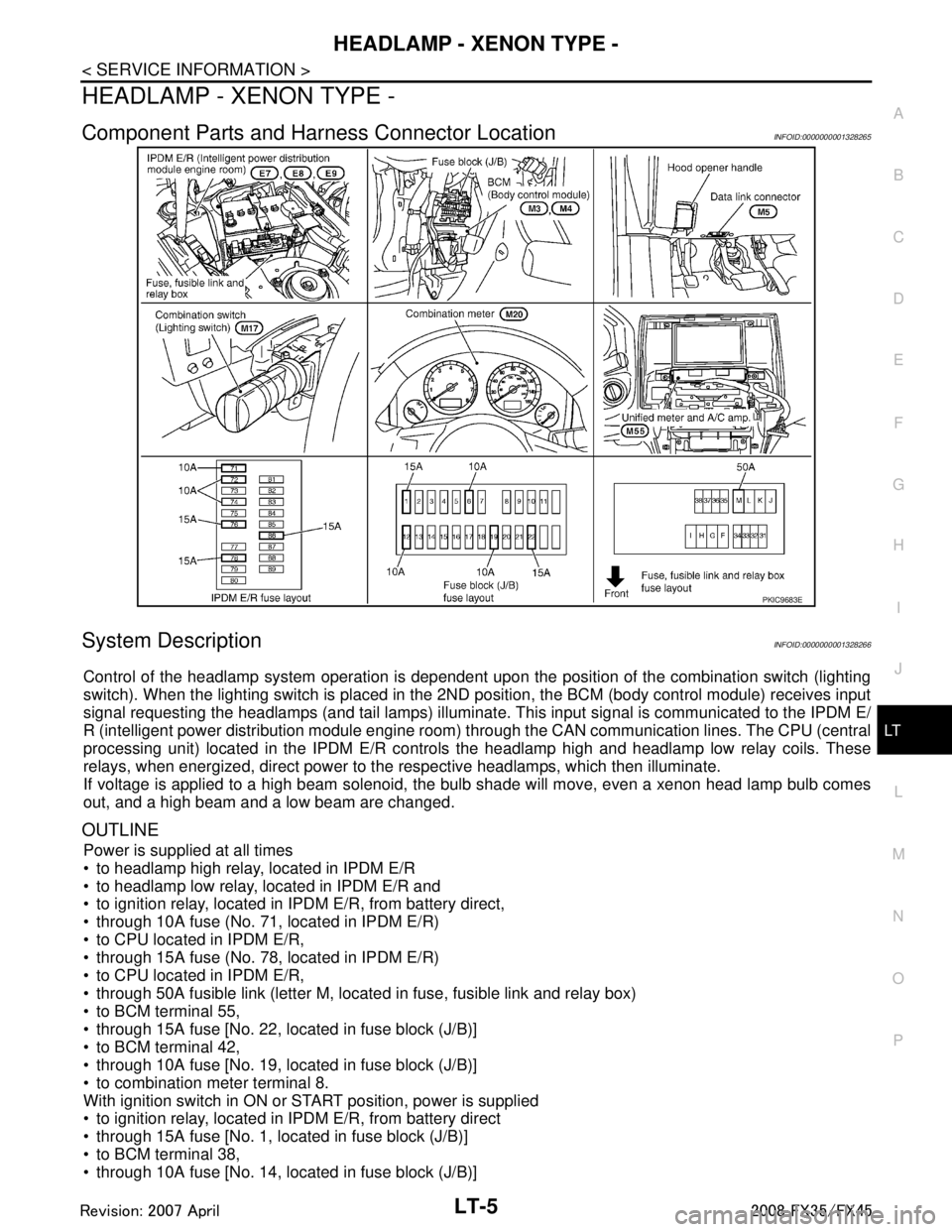
Component Parts and Har ness Connector LocationINFOID:0000000001328265
System DescriptionINFOID:0000000001328266
Control of the headlamp system operation is dependent upon t he position of the combination switch (lighting
switch). When the lighting switch is placed in the 2ND position, the BCM (body control module) receives input
signal requesting the headlamps (and tail lamps) illuminate. This input signal is communicated to the IPDM E/
R (intelligent power distribution module engine room) through the CAN communication lines. The CPU (central
processing unit) located in the IPDM E/R contro ls the headlamp high and headlamp low relay coils. These
relays, when energized, direct power to the respective headlamps, which then illuminate.
If voltage is applied to a high beam solenoid, the bulb shade will move, even a xenon head lamp bulb comes
out, and a high beam and a low beam are changed.
OUTLINE
Power is supplied at all times
to headlamp high relay, located in IPDM E/R
to headlamp low relay, located in IPDM E/R and
to ignition relay, located in IPDM E/R, from battery direct,
through 10A fuse (No. 71, located in IPDM E/R)
to CPU located in IPDM E/R,
through 15A fuse (No. 78, located in IPDM E/R)
to CPU located in IPDM E/R,
through 50A fusible link (letter M, located in fuse, fusible link and relay box)
to BCM terminal 55,
through 15A fuse [No. 22, located in fuse block (J/B)]
to BCM terminal 42,
through 10A fuse [No. 19, located in fuse block (J/B)]
to combination meter terminal 8.
With ignition switch in ON or START position, power is supplied
to ignition relay, located in IPDM E/R, from battery direct
through 15A fuse [No. 1, located in fuse block (J/B)]
to BCM terminal 38,
through 10A fuse [No. 14, located in fuse block (J/B)]
PKIC9683E
3AA93ABC3ACD3AC03ACA3AC03AC63AC53A913A773A893A873A873A8E3A773A983AC73AC93AC03AC3
3A893A873A873A8F3A773A9D3AAF3A8A3A8C3A863A9D3AAF3A8B3A8C
Page 3129 of 3924
HEADLAMP - XENON TYPE -LT-27
< SERVICE INFORMATION >
C
DE
F
G H
I
J
L
M A
B
LT
N
O P
Xenon Headlamp Trouble DiagnosisINFOID:0000000001328286
1.CHECK 1: XENON HEADLAMP LIGHTING
Install normal xenon bulb to corresponding xenon bulb headlamp, and check if lamp lights up.
OK or NG
OK >> Replace xenon bulb.
NG >> GO TO 2.
2.CHECK 2: XENON HEADLAMP LIGHTING
Install normal HID control unit to corresponding xenon headlamp, and check if lamp lights up.
OK or NG
OK >> Replace HID control unit.
NG >> GO TO 3.
3.CHECK 3: XENON HEADLAMP LIGHTING
Install normal xenon lamp housing assembly to corresponding xenon headlamp, and check if lamp lights up.
OK or NG
OK >> Replace xenon headlamp housing assembly. [Malfunction in starter (boosting circuit) in xenon headlamp housing]
NG >> INSPECTION END
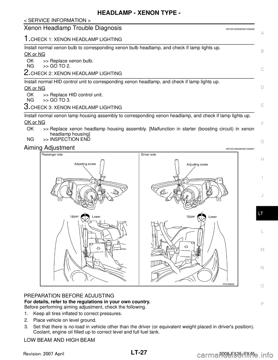
Aiming AdjustmentINFOID:0000000001328287
PREPARATION BEFORE ADJUSTING
For details, refer to the regulations in your own country.
Before performing aiming adjustment, check the following.
1. Keep all tires inflated to correct pressures.
2. Place vehicle on level ground.
3. Set that there is no-load in vehicle other than the driv er (or equivalent weight placed in driver's position).
Coolant, engine oil filled up to correct level and full fuel tank.
LOW BEAM AND HIGH BEAM
PKIC9684E
3AA93ABC3ACD3AC03ACA3AC03AC63AC53A913A773A893A873A873A8E3A773A983AC73AC93AC03AC3
3A893A873A873A8F3A773A9D3AAF3A8A3A8C3A863A9D3AAF3A8B3A8C
Page 3207 of 3924
COMBINATION SWITCHLT-105
< SERVICE INFORMATION >
C
DE
F
G H
I
J
L
M A
B
LT
N
O P
Example: When the HI BEAM switch is malfuncti oning, confirm that “TURN RH”, “HEAD LAMP 1” and
“LIGHT SW 1 ST” in System 5, to which the HI BEAM switch belongs, turn ON-OFF normally.
Without CONSULT-III
Operating combination switch, and confirm that other switches in malfunctioning system operate normally.
Example: When the HI BEAM switch is malfunctioni ng, confirm that “TURN RH”, “HEAD LAMP 1” and “LIGHT
SW 1 ST” in System 5, to which HI BE AM switch belongs, turn ON-OFF normally.
Check results
Other switches in malfunctioning system operate normally.>>Replace light ing switch or wiper switch.
Other switches in malfunctioning syst em do not operate normally.>>GO TO 3.
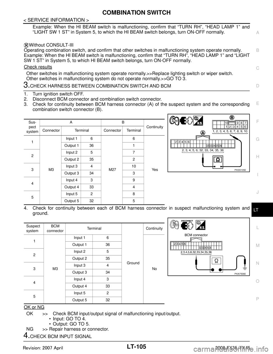
3.CHECK HARNESS BETWEEN COMB INATION SWITCH AND BCM
1. Turn ignition switch OFF.
2. Disconnect BCM connector and combination switch connector.
3. Check for continuity between BCM harness connecto r (A) of the suspect system and the corresponding
combination switch connector (B).
4. Check for continuity between each of BCM harne ss connector in suspect malfunctioning system and
ground.
OK or NG
OK >> Check BCM input/output signal of malfunctioning input/output.
Input: GO TO 4.
Output: GO TO 5.
NG >> Repair harness or connector.
4.CHECK BCM INPUT SIGNAL
Sus-
pect
system AB
Continuity
Connector Terminal Connector Terminal
1
M3 Input 1 6
M276
Ye s
Output 1 36 1
2 Input 2 5 7
Output 2 35 2
3 Input 3 4 10
Output 3 34 3
4 Input 4 3 9
Output 4 33 4
5 Input 5 2 8
Output 5 32 5
Suspect
system BCM
connector Te r m i n a l
GroundContinuity
1
M3 Input 1 6
No
Output 1 36
2 Input 2 5
Output 2 35
3 Input 3 4
Output 3 34
4 Input 4 3
Output 4 33
5 Input 5 2
Output 5 32
PKID0105E
PKIA7506E
3AA93ABC3ACD3AC03ACA3AC03AC63AC53A913A773A893A873A873A8E3A773A983AC73AC93AC03AC3
3A893A873A873A8F3A773A9D3AAF3A8A3A8C3A863A9D3AAF3A8B3A8C