2008 INFINITI FX35 combination meter removal
[x] Cancel search: combination meter removalPage 1145 of 3924
COMBINATION METERSDI-19
< SERVICE INFORMATION >
C
DE
F
G H
I
J
L
M A
B
DI
N
O P
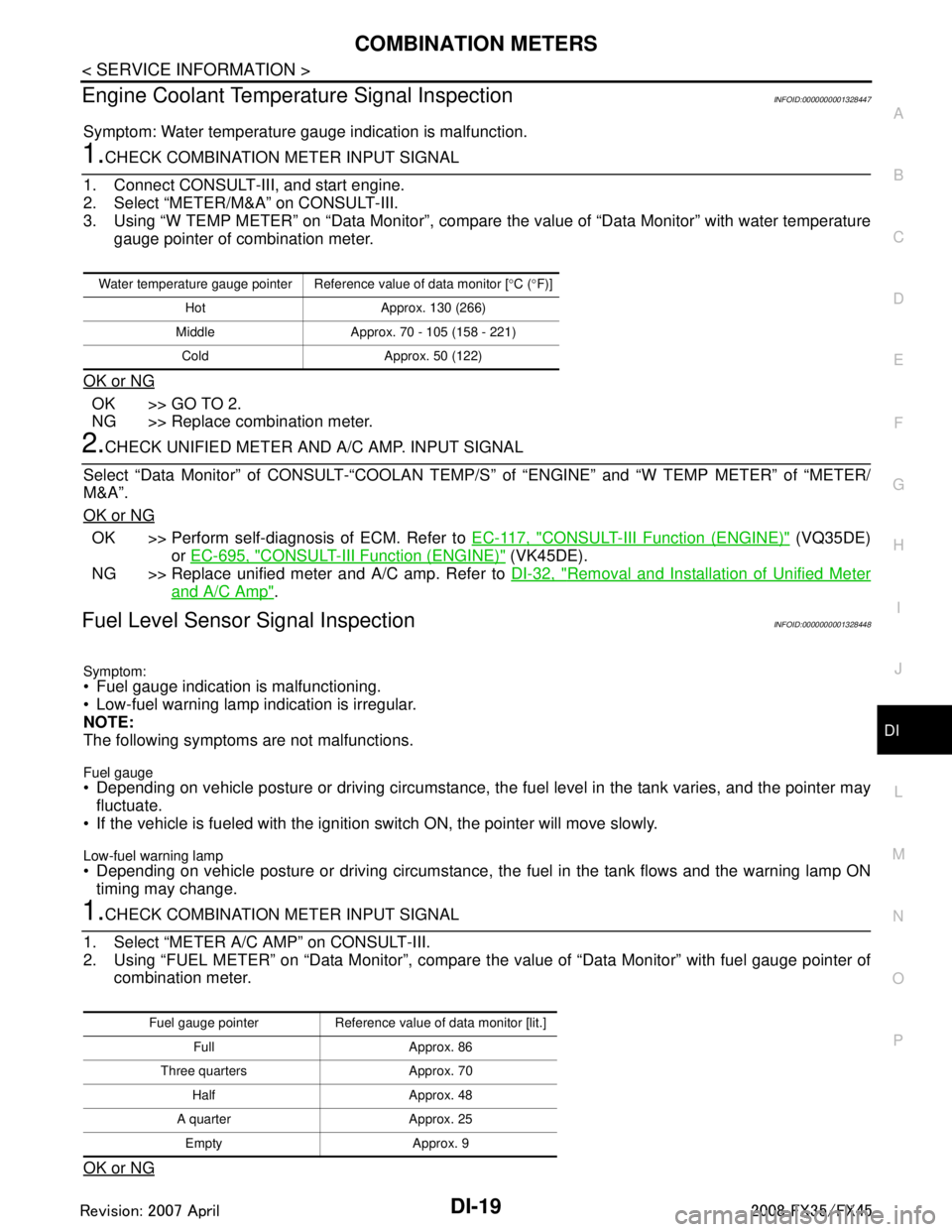
Engine Coolant Temperature Signal InspectionINFOID:0000000001328447
Symptom: Water temperature gauge indication is malfunction.
1.CHECK COMBINATION METER INPUT SIGNAL
1. Connect CONSULT-III, and start engine.
2. Select “METER/M&A” on CONSULT-III.
3. Using “W TEMP METER” on “Data Monitor”, compare the value of “Data Monitor” with water temperature
gauge pointer of combination meter.
OK or NG
OK >> GO TO 2.
NG >> Replace combination meter.
2.CHECK UNIFIED METER AND A/C AMP. INPUT SIGNAL
Select “Data Monitor” of CONSULT-“COOLAN TEMP/S ” of “ENGINE” and “W TEMP METER” of “METER/
M&A”.
OK or NG
OK >> Perform self-diagnosis of ECM. Refer to EC-117, "CONSULT-III Function (ENGINE)" (VQ35DE)
or EC-695, "
CONSULT-III Function (ENGINE)" (VK45DE).
NG >> Replace unified meter and A/C amp. Refer to DI-32, "
Removal and Installation of Unified Meter
and A/C Amp".
Fuel Level Sensor Signal InspectionINFOID:0000000001328448
Symptom:
Fuel gauge indication is malfunctioning.
Low-fuel warning lamp indication is irregular.
NOTE:
The following symptoms are not malfunctions.
Fuel gauge Depending on vehicle posture or driving circumstance, the fuel level in the tank varies, and the pointer may
fluctuate.
If the vehicle is fueled with the ignition switch ON, the pointer will move slowly.
Low-fuel warning lamp
Depending on vehicle posture or driving circumstance, t he fuel in the tank flows and the warning lamp ON
timing may change.
1.CHECK COMBINATION METER INPUT SIGNAL
1. Select “METER A/C AMP” on CONSULT-III.
2. Using “FUEL METER” on “Data Monitor”, compare t he value of “Data Monitor” with fuel gauge pointer of
combination meter.
OK or NG
Water temperature gauge pointer Reference value of data monitor [ °C ( °F)]
Hot Approx. 130 (266)
Middle Approx. 70 - 105 (158 - 221) Cold Approx. 50 (122)
Fuel gauge pointer Reference value of data monitor [lit.] Full Approx. 86
Three quarters Approx. 70 Half Approx. 48
A quarter Approx. 25 Empty Approx. 9
3AA93ABC3ACD3AC03ACA3AC03AC63AC53A913A773A893A873A873A8E3A773A983AC73AC93AC03AC3
3A893A873A873A8F3A773A9D3AAF3A8A3A8C3A863A9D3AAF3A8B3A8C
Page 1147 of 3924
COMBINATION METERSDI-21
< SERVICE INFORMATION >
C
DE
F
G H
I
J
L
M A
B
DI
N
O P
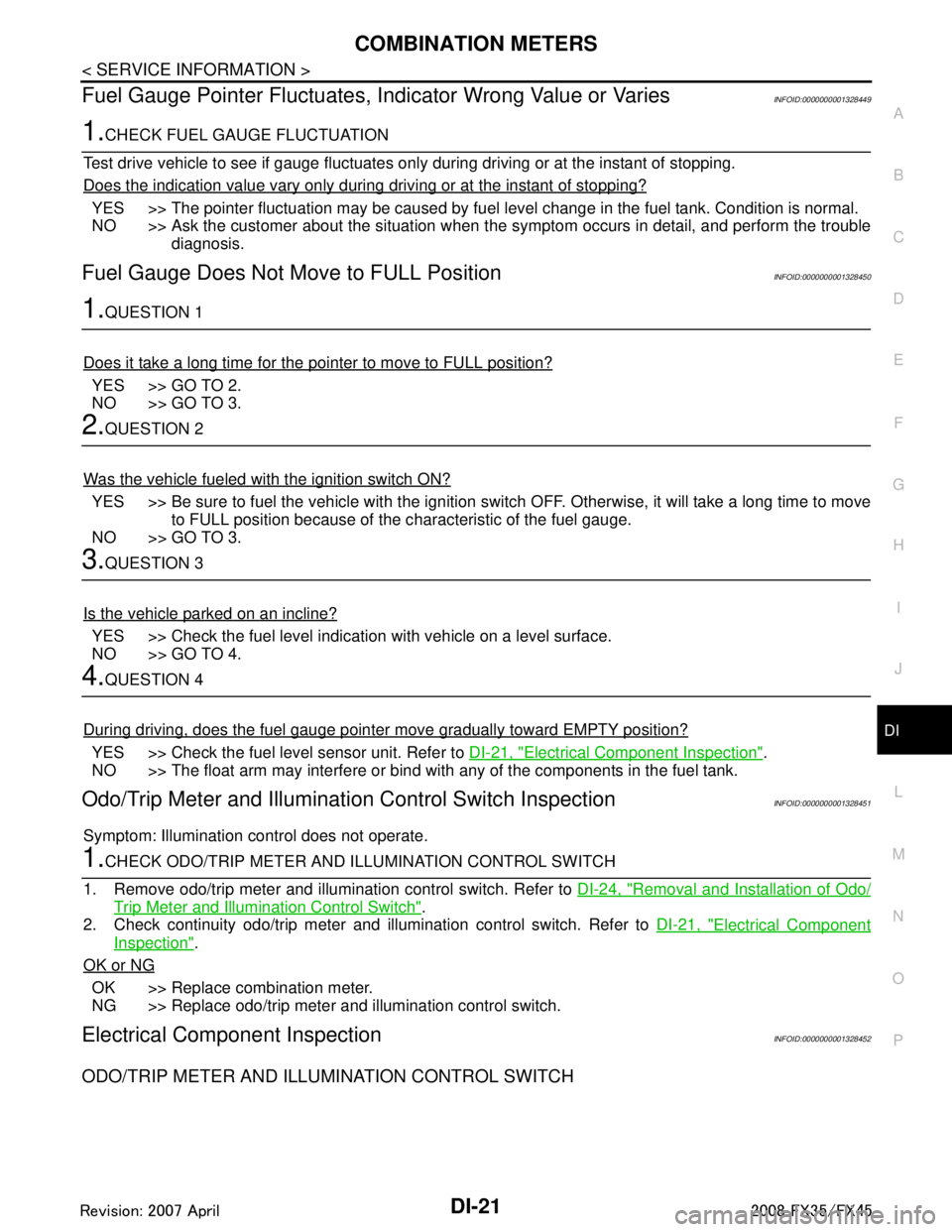
Fuel Gauge Pointer Fluctuates, Indicator Wrong Value or VariesINFOID:0000000001328449
1.CHECK FUEL GAUGE FLUCTUATION
Test drive vehicle to see if gauge fluctuates onl y during driving or at the instant of stopping.
Does the indication value vary only during driving or at the instant of stopping?
YES >> The pointer fluctuation may be caused by fuel level change in the fuel tank. Condition is normal.
NO >> Ask the customer about the situation when the symptom occurs in detail, and perform the trouble
diagnosis.
Fuel Gauge Does Not Move to FULL PositionINFOID:0000000001328450
1.QUESTION 1
Does it take a long time for the pointer to move to FULL position?
YES >> GO TO 2.
NO >> GO TO 3.
2.QUESTION 2
Was the vehicle fueled with the ignition switch ON?
YES >> Be sure to fuel the vehicle with the ignition swit ch OFF. Otherwise, it will take a long time to move
to FULL position because of the c haracteristic of the fuel gauge.
NO >> GO TO 3.
3.QUESTION 3
Is the vehicle parked on an incline?
YES >> Check the fuel level indication with vehicle on a level surface.
NO >> GO TO 4.
4.QUESTION 4
During driving, does the fuel gauge pointer move gradually toward EMPTY position?
YES >> Check the fuel level sensor unit. Refer to DI-21, "Electrical Component Inspection".
NO >> The float arm may interfere or bind with any of the components in the fuel tank.
Odo/Trip Meter and Illuminati on Control Switch InspectionINFOID:0000000001328451
Symptom: Illumination control does not operate.
1.CHECK ODO/TRIP METER AND I LLUMINATION CONTROL SWITCH
1. Remove odo/trip meter and illumination control switch. Refer to DI-24, "
Removal and Installation of Odo/
Trip Meter and Illumination Control Switch".
2. Check continuity odo/trip meter and illumination control switch. Refer to DI-21, "
Electrical Component
Inspection".
OK or NG
OK >> Replace combination meter.
NG >> Replace odo/trip meter and illumination control switch.
Electrical Component InspectionINFOID:0000000001328452
ODO/TRIP METER AND ILLUMINATION CONTROL SWITCH
3AA93ABC3ACD3AC03ACA3AC03AC63AC53A913A773A893A873A873A8E3A773A983AC73AC93AC03AC3
3A893A873A873A8F3A773A9D3AAF3A8A3A8C3A863A9D3AAF3A8B3A8C
Page 1148 of 3924
DI-22
< SERVICE INFORMATION >
COMBINATION METERS
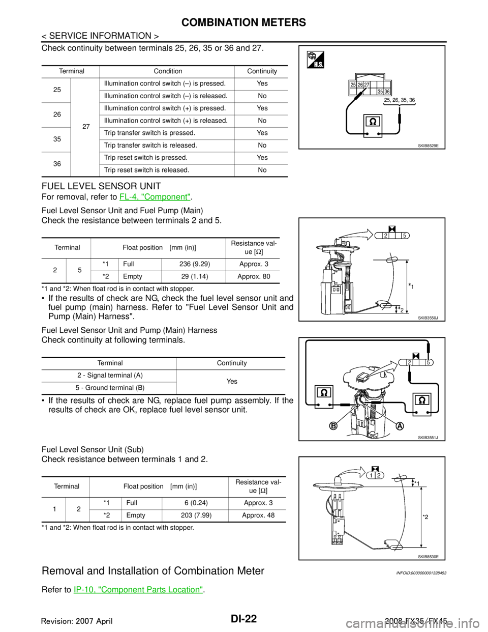
Check continuity between terminals 25, 26, 35 or 36 and 27.
FUEL LEVEL SENSOR UNIT
For removal, refer to FL-4, "Component".
Fuel Level Sensor Unit and Fuel Pump (Main)
Check the resistance between terminals 2 and 5.
*1 and *2: When float rod is in contact with stopper.
If the results of check are NG, check the fuel level sensor unit and
fuel pump (main) harness. Refer to "Fuel Level Sensor Unit and
Pump (Main) Harness".
Fuel Level Sensor Unit and Pump (Main) Harness
Check continuity at following terminals.
If the results of check are NG, replace fuel pump assembly. If the results of check are OK, replace fuel level sensor unit.
Fuel Level Sensor Unit (Sub)
Check resistance between terminals 1 and 2.
*1 and *2: When float rod is in contact with stopper.
Removal and Installation of Combination MeterINFOID:0000000001328453
Refer to IP-10, "Component Parts Location".
Terminal Condition Continuity
25
27Illumination control swit
ch (–) is pressed. Yes
Illumination control swit ch (–) is released. No
26 Illumination control swit
ch (+) is pressed. Yes
Illumination control swit ch (+) is released. No
35 Trip transfer switch is pressed. Yes
Trip transfer switch is released. No
36 Trip reset switch is pressed. Yes
Trip reset switch is released. No
SKIB8529E
Terminal Float position [mm (in)]
Resistance val-
ue [Ω]
25 *1 Full 236 (9.29) Approx. 3
*2 Empty 29 (1.14) Approx. 80
SKIB3550J
Terminal Continuity
2 - Signal terminal (A) Ye s
5 - Ground terminal (B)
SKIB3551J
Terminal Float position [mm (in)] Resistance val-
ue [Ω]
12 *1 Full 6 (0.24) Approx. 3
*2 Empty 203 (7.99) Approx. 48
SKIB8530E
3AA93ABC3ACD3AC03ACA3AC03AC63AC53A913A773A893A873A873A8E3A773A983AC73AC93AC03AC3
3A893A873A873A8F3A773A9D3AAF3A8A3A8C3A863A9D3AAF3A8B3A8C
Page 1150 of 3924
DI-24
< SERVICE INFORMATION >
COMBINATION METERS
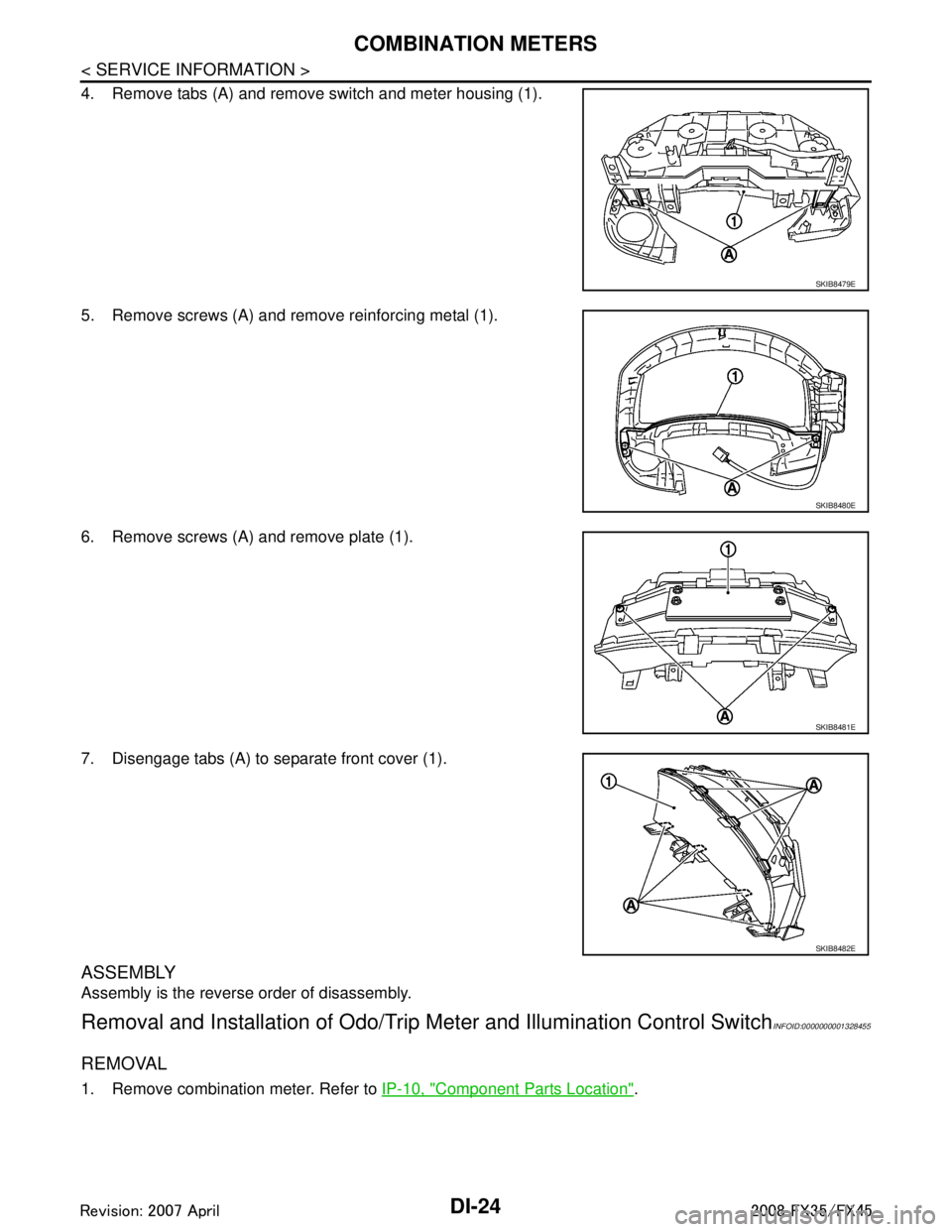
4. Remove tabs (A) and remove switch and meter housing (1).
5. Remove screws (A) and remove reinforcing metal (1).
6. Remove screws (A) and remove plate (1).
7. Disengage tabs (A) to separate front cover (1).
ASSEMBLY
Assembly is the reverse order of disassembly.
Removal and Installation of Odo/Trip Meter and Illumination Control SwitchINFOID:0000000001328455
REMOVAL
1. Remove combination meter. Refer to IP-10, "Component Parts Location".
SKIB8479E
SKIB8480E
SKIB8481E
SKIB8482E
3AA93ABC3ACD3AC03ACA3AC03AC63AC53A913A773A893A873A873A8E3A773A983AC73AC93AC03AC3
3A893A873A873A8F3A773A9D3AAF3A8A3A8C3A863A9D3AAF3A8B3A8C
Page 1151 of 3924
COMBINATION METERSDI-25
< SERVICE INFORMATION >
C
DE
F
G H
I
J
L
M A
B
DI
N
O P
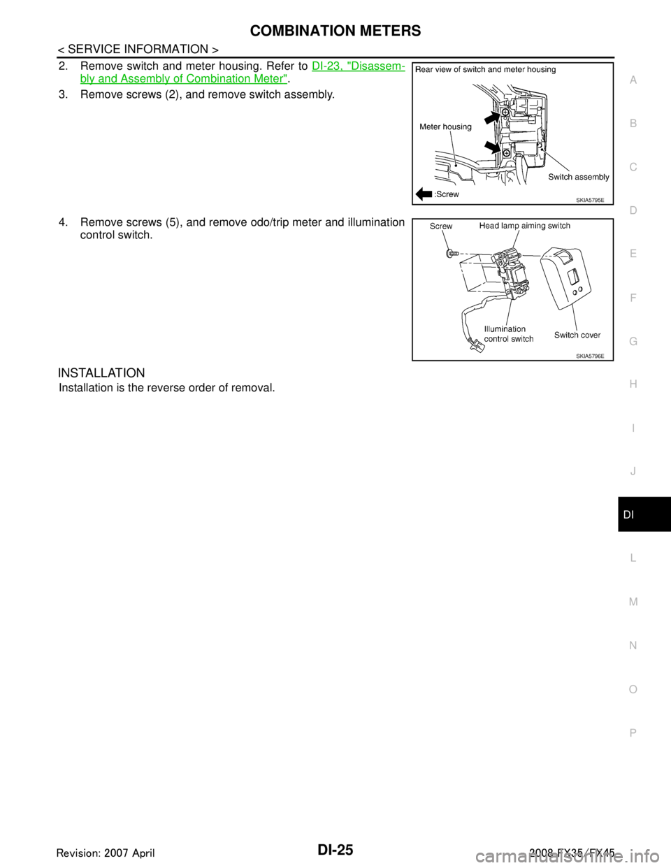
2. Remove switch and meter housing. Refer to DI-23, "Disassem-
bly and Assembly of Combination Meter".
3. Remove screws (2), and remove switch assembly.
4. Remove screws (5), and remove odo/trip meter and illumination control switch.
INSTALLATION
Installation is the reverse order of removal.
SKIA5795E
SKIA5796E
3AA93ABC3ACD3AC03ACA3AC03AC63AC53A913A773A893A873A873A8E3A773A983AC73AC93AC03AC3
3A893A873A873A8F3A773A9D3AAF3A8A3A8C3A863A9D3AAF3A8B3A8C
Page 1157 of 3924
UNIFIED METER AND A/C AMPDI-31
< SERVICE INFORMATION >
C
DE
F
G H
I
J
L
M A
B
DI
N
O P
NO >> GO TO 6.
3.CHECK CONTINUITY COMM UNICATION CIRCUIT (TX: COMBINATION METER)
1. Turn ignition switch OFF.
2. Disconnect combination meter connector and unified meter and A/C amp. connector.
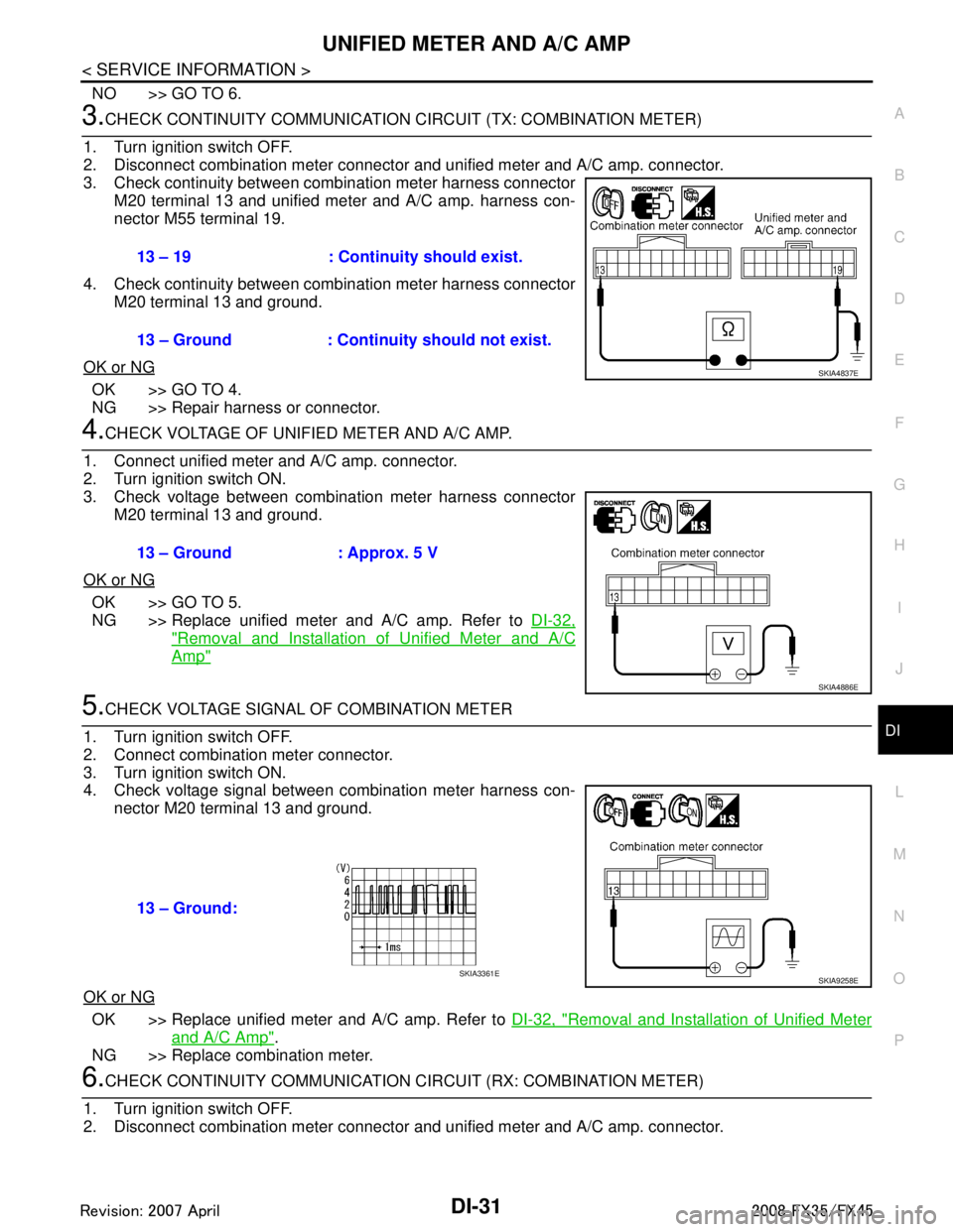
3. Check continuity between combination meter harness connector M20 terminal 13 and unified meter and A/C amp. harness con-
nector M55 terminal 19.
4. Check continuity between combination meter harness connector M20 terminal 13 and ground.
OK or NG
OK >> GO TO 4.
NG >> Repair harness or connector.
4.CHECK VOLTAGE OF UNIFIED METER AND A/C AMP.
1. Connect unified meter and A/C amp. connector.
2. Turn ignition switch ON.
3. Check voltage between combination meter harness connector M20 terminal 13 and ground.
OK or NG
OK >> GO TO 5.
NG >> Replace unified meter and A/C amp. Refer to DI-32,
"Removal and Installation of Unified Meter and A/C
Amp"
5.CHECK VOLTAGE SIGNAL OF COMBINATION METER
1. Turn ignition switch OFF.
2. Connect combination meter connector.
3. Turn ignition switch ON.
4. Check voltage signal between combination meter harness con- nector M20 terminal 13 and ground.
OK or NG
OK >> Replace unified meter and A/C amp. Refer to DI-32, "Removal and Installation of Unified Meter
and A/C Amp".
NG >> Replace combination meter.
6.CHECK CONTINUITY COMM UNICATION CIRCUIT (RX: COMBINATION METER)
1. Turn ignition switch OFF.
2. Disconnect combination meter connector and unified meter and A/C amp. connector.
13 – 19 : Continuity should exist.
13 – Ground : Continuity should not exist.
SKIA4837E
13 – Ground : Approx. 5 V
SKIA4886E
13 – Ground:
SKIA9258ESKIA3361E
3AA93ABC3ACD3AC03ACA3AC03AC63AC53A913A773A893A873A873A8E3A773A983AC73AC93AC03AC3
3A893A873A873A8F3A773A9D3AAF3A8A3A8C3A863A9D3AAF3A8B3A8C
Page 1158 of 3924
DI-32
< SERVICE INFORMATION >
UNIFIED METER AND A/C AMP
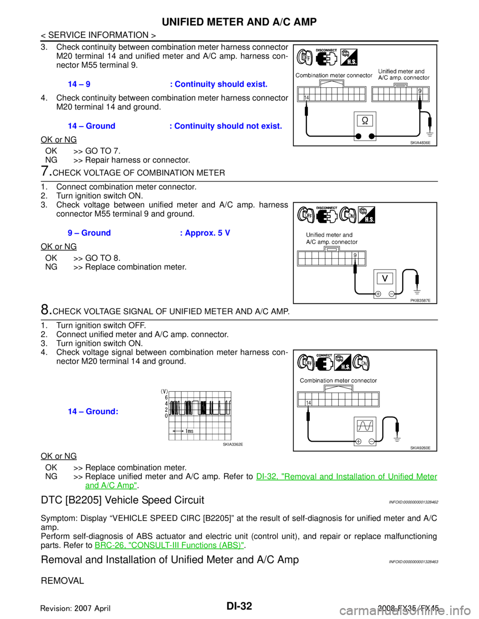
3. Check continuity between combination meter harness connectorM20 terminal 14 and unified meter and A/C amp. harness con-
nector M55 terminal 9.
4. Check continuity between combination meter harness connector M20 terminal 14 and ground.
OK or NG
OK >> GO TO 7.
NG >> Repair harness or connector.
7.CHECK VOLTAGE OF COMBINATION METER
1. Connect combination meter connector.
2. Turn ignition switch ON.
3. Check voltage between unified meter and A/C amp. harness connector M55 terminal 9 and ground.
OK or NG
OK >> GO TO 8.
NG >> Replace combination meter.
8.CHECK VOLTAGE SIGNAL OF UNIFIED METER AND A/C AMP.
1. Turn ignition switch OFF.
2. Connect unified meter and A/C amp. connector.
3. Turn ignition switch ON.
4. Check voltage signal between combination meter harness con- nector M20 terminal 14 and ground.
OK or NG
OK >> Replace combination meter.
NG >> Replace unified meter and A/C amp. Refer to DI-32, "
Removal and Installation of Unified Meter
and A/C Amp".
DTC [B2205] Vehicle Speed CircuitINFOID:0000000001328462
Symptom: Display “VEHICLE SPEED CIRC [B2205]” at the result of self-diagnosis for unified meter and A/C
amp.
Perform self-diagnosis of ABS actuator and electric unit (control unit), and repair or replace malfunctioning
parts. Refer to BRC-26, "
CONSULT-III Functions (ABS)".
Removal and Installation of Unified Meter and A/C AmpINFOID:0000000001328463
REMOVAL
14 – 9 : Continuity should exist.
14 – Ground : Continuity should not exist.
SKIA4836E
9 – Ground : Approx. 5 V
PKIB3587E
14 – Ground:
SKIA9260ESKIA3362E
3AA93ABC3ACD3AC03ACA3AC03AC63AC53A913A773A893A873A873A8E3A773A983AC73AC93AC03AC3
3A893A873A873A8F3A773A9D3AAF3A8A3A8C3A863A9D3AAF3A8B3A8C
Page 1170 of 3924
DI-44
< SERVICE INFORMATION >
WARNING LAMPS
2.CHECK IPDM E/R INPUT SIGNAL
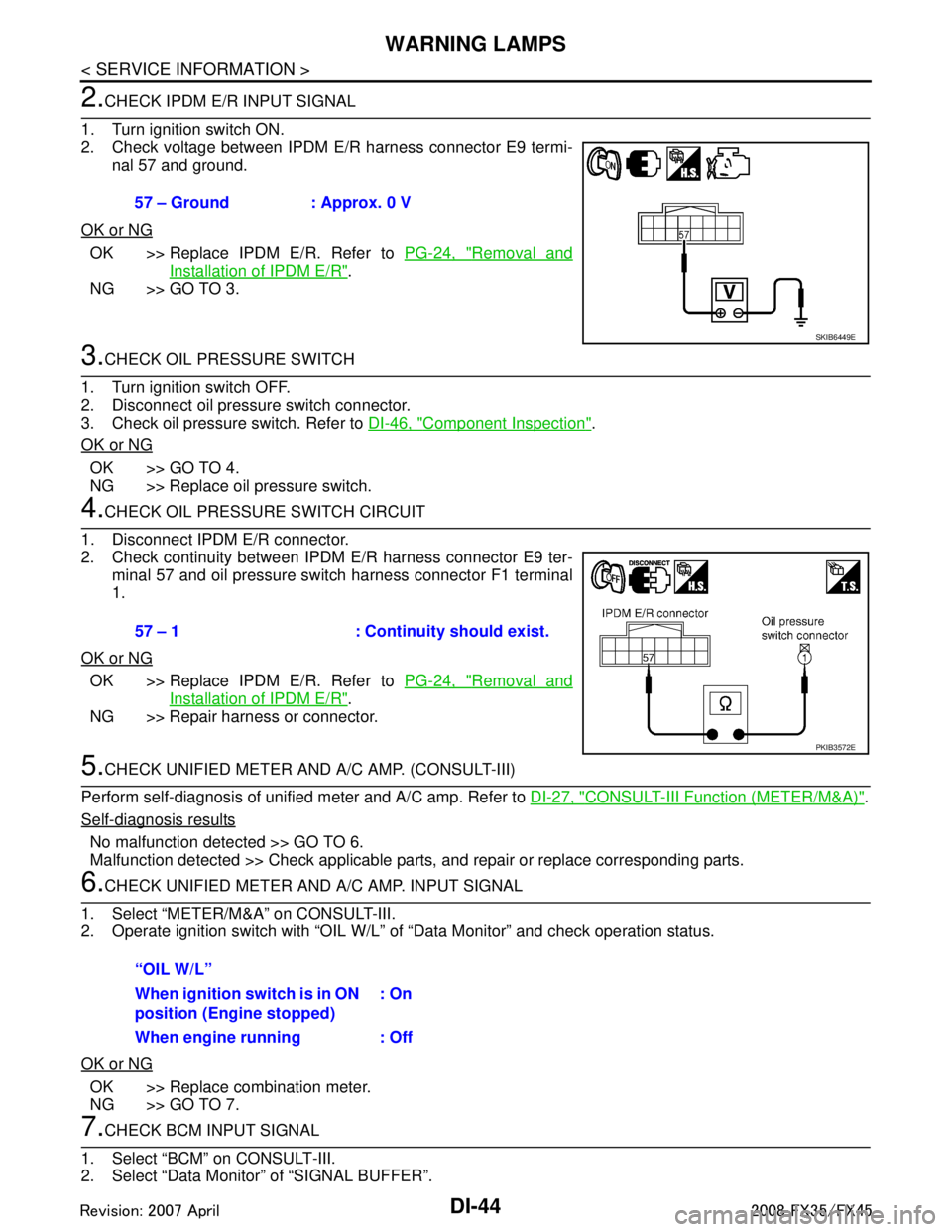
1. Turn ignition switch ON.
2. Check voltage between IPDM E/R harness connector E9 termi- nal 57 and ground.
OK or NG
OK >> Replace IPDM E/R. Refer to PG-24, "Removal and
Installation of IPDM E/R".
NG >> GO TO 3.
3.CHECK OIL PRESSURE SWITCH
1. Turn ignition switch OFF.
2. Disconnect oil pressure switch connector.
3. Check oil pressure switch. Refer to DI-46, "
Component Inspection".
OK or NG
OK >> GO TO 4.
NG >> Replace oil pressure switch.
4.CHECK OIL PRESSURE SWITCH CIRCUIT
1. Disconnect IPDM E/R connector.
2. Check continuity between IPDM E/R harness connector E9 ter- minal 57 and oil pressure switch harness connector F1 terminal
1.
OK or NG
OK >> Replace IPDM E/R. Refer to PG-24, "Removal and
Installation of IPDM E/R".
NG >> Repair harness or connector.
5.CHECK UNIFIED METER AND A/C AMP. (CONSULT-III)
Perform self-diagnosis of unified meter and A/C amp. Refer to DI-27, "
CONSULT-III Function (METER/M&A)".
Self-diagnosis results
No malfunction detected >> GO TO 6.
Malfunction detected >> Check applicable parts, and repair or replace corresponding parts.
6.CHECK UNIFIED METER AND A/C AMP. INPUT SIGNAL
1. Select “METER/M&A” on CONSULT-III.
2. Operate ignition switch with “OIL W/L” of “Data Monitor” and check operation status.
OK or NG
OK >> Replace combination meter.
NG >> GO TO 7.
7.CHECK BCM INPUT SIGNAL
1. Select “BCM” on CONSULT-III.
2. Select “Data Monitor” of “SIGNAL BUFFER”. 57 – Ground : Approx. 0 V
SKIB6449E
57 – 1 : Continuity should exist.
PKIB3572E
“OIL W/L”
When ignition switch is in ON
position (Engine stopped)
: On
When engine running : Off
3AA93ABC3ACD3AC03ACA3AC03AC63AC53A913A773A893A873A873A8E3A773A983AC73AC93AC03AC3
3A893A873A873A8F3A773A9D3AAF3A8A3A8C3A863A9D3AAF3A8B3A8C