2008 INFINITI FX35 combination meter removal
[x] Cancel search: combination meter removalPage 3017 of 3924
IP-16
< SERVICE INFORMATION >
INSTRUMENT PANEL ASSEMBLY
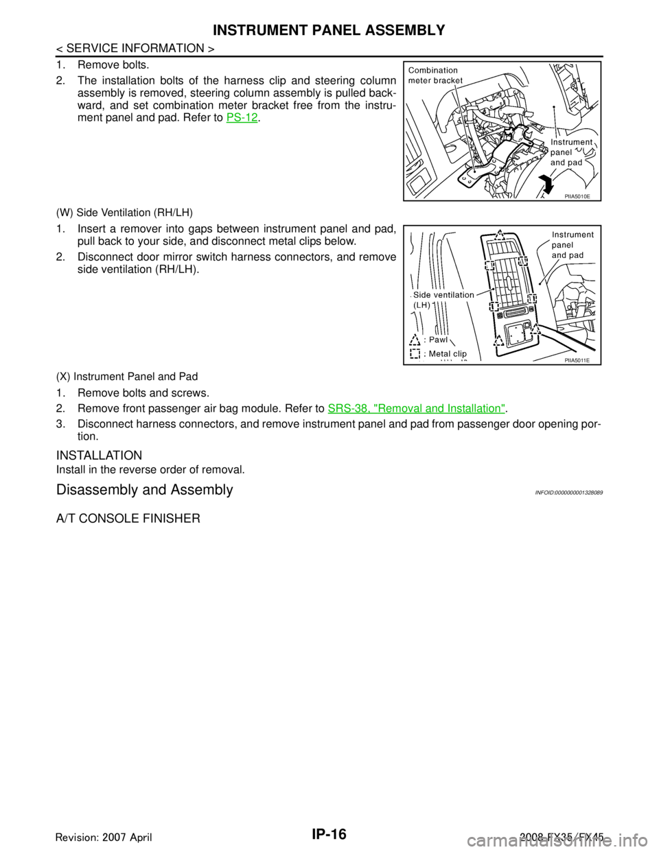
1. Remove bolts.
2. The installation bolts of the harness clip and steering columnassembly is removed, steering column assembly is pulled back-
ward, and set combination meter bracket free from the instru-
ment panel and pad. Refer to PS-12
.
(W) Side Ventilation (RH/LH)
1. Insert a remover into gaps between instrument panel and pad,
pull back to your side, and disconnect metal clips below.
2. Disconnect door mirror switch harness connectors, and remove side ventilation (RH/LH).
(X) Instrument Panel and Pad
1. Remove bolts and screws.
2. Remove front passenger air bag module. Refer to SRS-38, "
Removal and Installation".
3. Disconnect harness connectors, and remove instrum ent panel and pad from passenger door opening por-
tion.
INSTALLATION
Install in the reverse order of removal.
Disassembly and AssemblyINFOID:0000000001328089
A/T CONSOLE FINISHER
PIIA5010E
PIIA5011E
3AA93ABC3ACD3AC03ACA3AC03AC63AC53A913A773A893A873A873A8E3A773A983AC73AC93AC03AC3
3A893A873A873A8F3A773A9D3AAF3A8A3A8C3A863A9D3AAF3A8B3A8C
Page 3167 of 3924
HEADLAMP AIMING CONTROLLT-65
< SERVICE INFORMATION >
C
DE
F
G H
I
J
L
M A
B
LT
N
O P
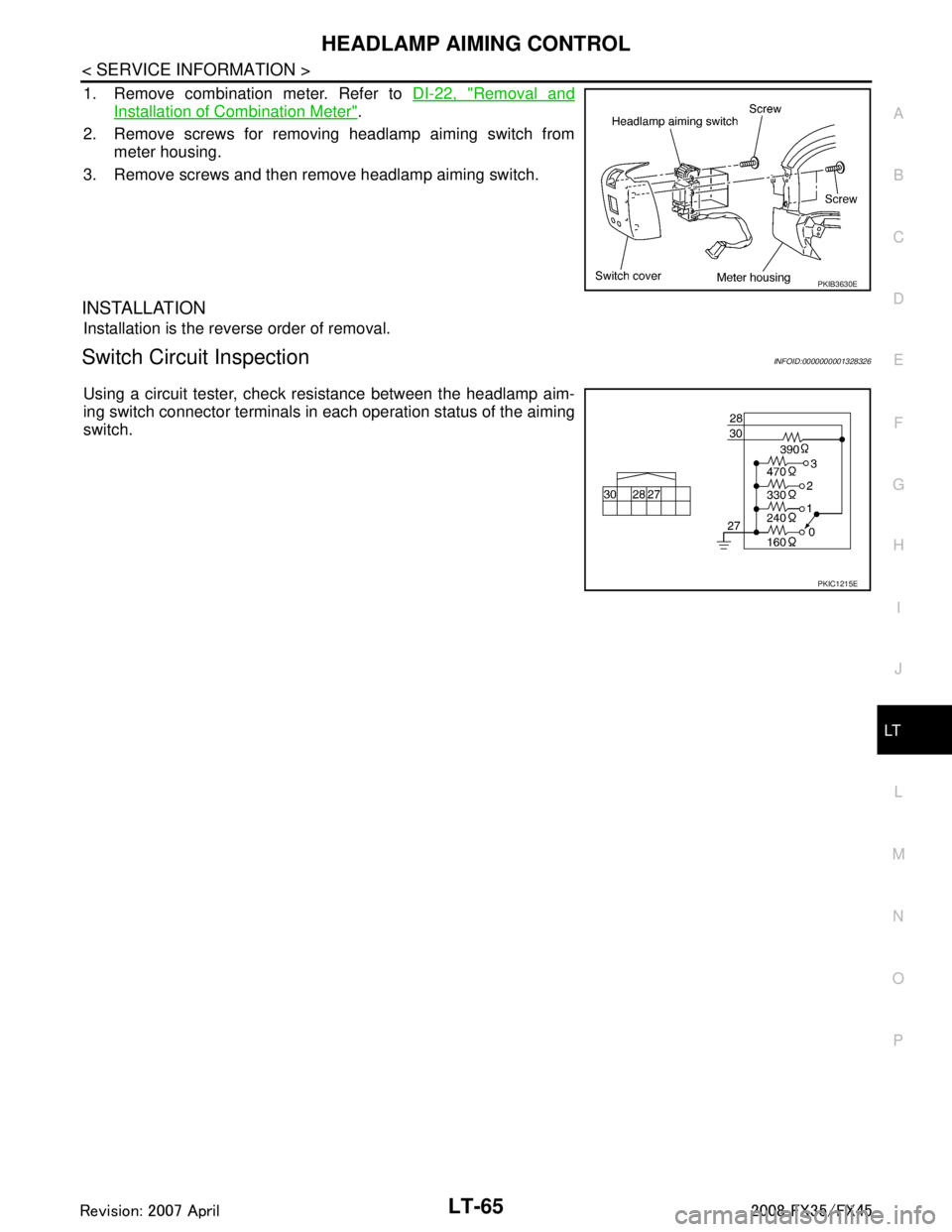
1. Remove combination meter. Refer to DI-22, "Removal and
Installation of Combination Meter".
2. Remove screws for removing headlamp aiming switch from meter housing.
3. Remove screws and then remove headlamp aiming switch.
INSTALLATION
Installation is the reverse order of removal.
Switch Circuit InspectionINFOID:0000000001328326
Using a circuit tester, check resistance between the headlamp aim-
ing switch connector terminals in each operation status of the aiming
switch.
PKIB3630E
PKIC1215E
3AA93ABC3ACD3AC03ACA3AC03AC63AC53A913A773A893A873A873A8E3A773A983AC73AC93AC03AC3
3A893A873A873A8F3A773A9D3AAF3A8A3A8C3A863A9D3AAF3A8B3A8C
Page 3266 of 3924
LT-164
< SERVICE INFORMATION >
INTERIOR ROOM LAMP
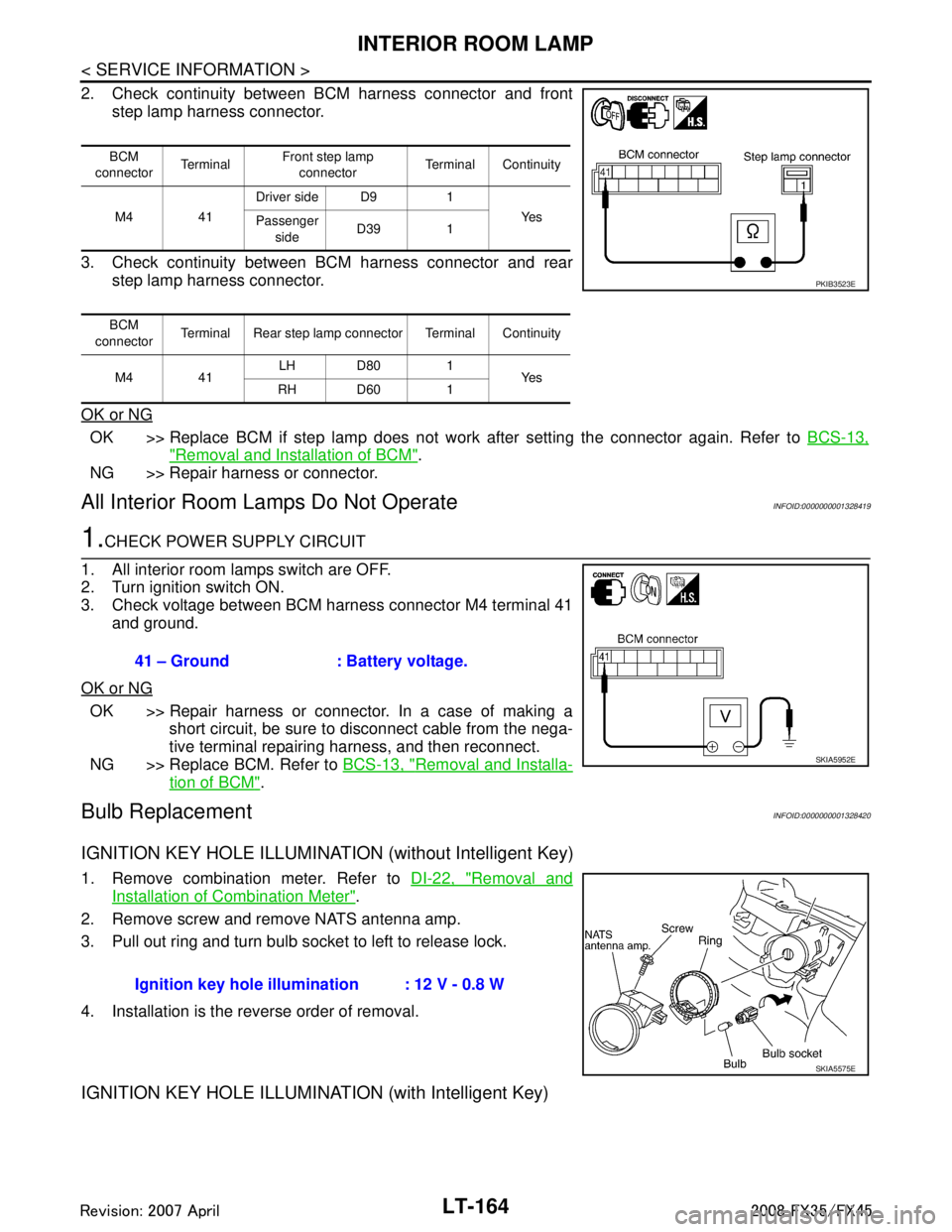
2. Check continuity between BCM harness connector and frontstep lamp harness connector.
3. Check continuity between BCM harness connector and rear step lamp harness connector.
OK or NG
OK >> Replace BCM if step lamp does not work after setting the connector again. Refer to BCS-13,
"Removal and Installation of BCM".
NG >> Repair harness or connector.
All Interior Room La mps Do Not OperateINFOID:0000000001328419
1.CHECK POWER SUPPLY CIRCUIT
1. All interior room lamps switch are OFF.
2. Turn ignition switch ON.
3. Check voltage between BCM harness connector M4 terminal 41 and ground.
OK or NG
OK >> Repair harness or connector. In a case of making a short circuit, be sure to disconnect cable from the nega-
tive terminal repairing harness, and then reconnect.
NG >> Replace BCM. Refer to BCS-13, "
Removal and Installa-
tion of BCM".
Bulb ReplacementINFOID:0000000001328420
IGNITION KEY HOLE ILLUMINATION (without Intelligent Key)
1. Remove combination meter. Refer to DI-22, "Removal and
Installation of Combination Meter".
2. Remove screw and remove NATS antenna amp.
3. Pull out ring and turn bulb socket to left to release lock.
4. Installation is the reverse order of removal.
IGNITION KEY HOLE ILLUMINA TION (with Intelligent Key)
BCM
connector Te r m i n a l Front step lamp
connector Terminal Continuity
M4 41 Driver side D9 1
Ye s
Passenger
side D39 1
BCM
connector Terminal Rear step lamp connector Terminal Continuity
M4 41 LH D80 1
Ye s
RH D60 1
PKIB3523E
41 – Ground : Battery voltage.
SKIA5952E
Ignition key hole illu mination : 12 V - 0.8 W
SKIA5575E
3AA93ABC3ACD3AC03ACA3AC03AC63AC53A913A773A893A873A873A8E3A773A983AC73AC93AC03AC3
3A893A873A873A8F3A773A9D3AAF3A8A3A8C3A863A9D3AAF3A8B3A8C
Page 3467 of 3924
PS-12
< SERVICE INFORMATION >
STEERING COLUMN
STEERING COLUMN
Removal and InstallationINFOID:0000000001327714
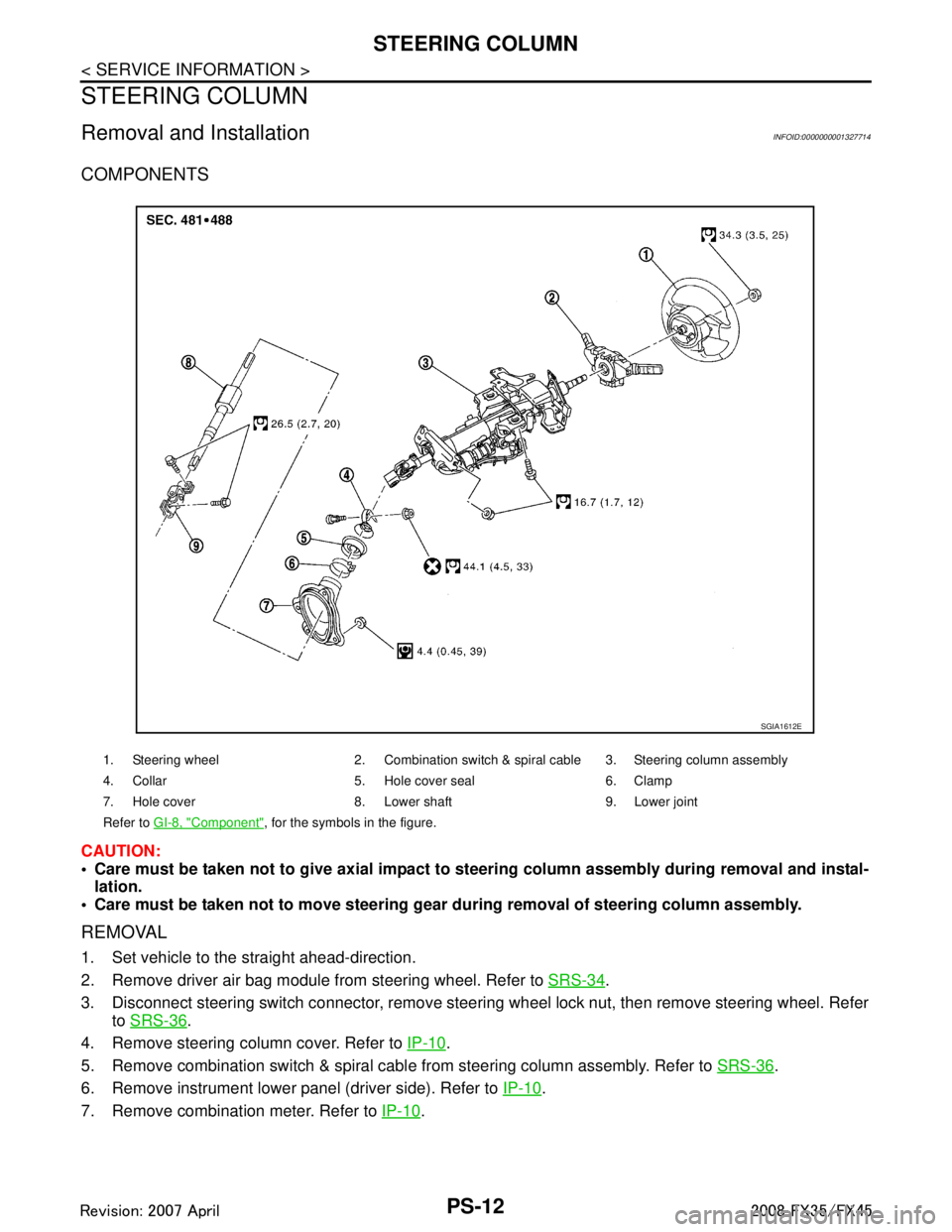
COMPONENTS
CAUTION:
Care must be taken not to give axial impact to steering column assembly during removal and instal-
lation.
Care must be taken not to move steering gear during removal of steering column assembly.
REMOVAL
1. Set vehicle to the straight ahead-direction.
2. Remove driver air bag module from steering wheel. Refer to SRS-34
.
3. Disconnect steering switch connector, remove steering wheel lock nut, then remove steering wheel. Refer to SRS-36
.
4. Remove steering column cover. Refer to IP-10
.
5. Remove combination switch & spiral cabl e from steering column assembly. Refer to SRS-36
.
6. Remove instrument lower panel (driver side). Refer to IP-10
.
7. Remove combination meter. Refer to IP-10
.
1. Steering wheel 2. Combination switch & spiral cable 3. Steering column assembly
4. Collar 5. Hole cover seal 6. Clamp
7. Hole cover 8. Lower shaft 9. Lower joint
Refer to GI-8, "
Component", for the symbols in the figure.
SGIA1612E
3AA93ABC3ACD3AC03ACA3AC03AC63AC53A913A773A893A873A873A8E3A773A983AC73AC93AC03AC3
3A893A873A873A8F3A773A9D3AAF3A8A3A8C3A863A9D3AAF3A8B3A8C
Page 3521 of 3924

RF-6
< SERVICE INFORMATION >
SQUEAK AND RATTLE TROUBLE DIAGNOSES
Insulates where slight movement is present. Ideal for instrument panel applications.
SILICONE GREASE
Used in place of UHMW tape that will be visible or not fit.
Note: Will only last a few months.
SILICONE SPRAY
Use when grease cannot be applied.
DUCT TAPE
Use to eliminate movement.
CONFIRM THE REPAIR
Confirm that the cause of a noise is repaired by test driving the vehicle. Operate the vehicle under the same
conditions as when the noise originally occurred. Refer to the notes on the Diagnostic Worksheet.
Generic Squeak and Rattle TroubleshootingINFOID:0000000001328031
Refer to Table of Contents for specific component removal and installation information.
INSTRUMENT PANEL
Most incidents are caused by contact and movement between:
1. Cluster lid A and instrument panel
2. Acrylic lens and combination meter housing
3. Instrument panel to front pillar garnish
4. Instrument panel to windshield
5. Instrument panel mounting pins
6. Wiring harnesses behind the combination meter
7. A/C defroster duct and duct joint
These incidents can usually be located by tapping or moving the components to duplicate the noise or by
pressing on the components while driving to stop the noi se. Most of these incidents can be repaired by apply-
ing felt cloth tape or silicon spray (in hard to reach areas).Urethane pads can be used to insulate wiring har-
ness.
CAUTION:
Do not use silicone spray to isolate a squeak or ra ttle. If you saturate the area with silicone, you will
not be able to recheck the repair.
CENTER CONSOLE
Components to pay attention to include:
1. Shifter assembly cover to finisher
2. A/C control unit and cluster lid C
3. Wiring harnesses behind audio and A/C control unit
The instrument panel repair and isolation pr ocedures also apply to the center console.
DOORS
Pay attention to the:
1. Finisher and inner panel making a slapping noise
2. Inside handle escutcheon to door finisher
3. Wiring harnesses tapping
4. Door striker out of alignment causing a popping noise on starts and stops
Tapping or moving the components or pressing on them wh ile driving to duplicate the conditions can isolate
many of these incidents. You can usually insulate the areas with felt cloth tape or insulator foam blocks from
the Nissan Squeak and Rattle Kit (J43980) to repair the noise.
TRUNK
Trunk noises are often caused by a loose jack or loose items put into the trunk by the owner.
In addition look for:
1. Trunk lid dumpers out of adjustment
2. Trunk lid striker out of adjustment
3. Trunk lid torsion bars knocking together
4. A loose license plate or bracket
3AA93ABC3ACD3AC03ACA3AC03AC63AC53A913A773A893A873A873A8E3A773A983AC73AC93AC03AC3
3A893A873A873A8F3A773A9D3AAF3A8A3A8C3A863A9D3AAF3A8B3A8C
Page 3647 of 3924

SE-8
< SERVICE INFORMATION >
SQUEAK AND RATTLE TROUBLE DIAGNOSES
Insulates where slight movement is present. Ideal for instrument panel applications.
SILICONE GREASE
Used in place of UHMW tape that will be visible or not fit.
Note: Will only last a few months.
SILICONE SPRAY
Use when grease cannot be applied.
DUCT TAPE
Use to eliminate movement.
CONFIRM THE REPAIR
Confirm that the cause of a noise is repaired by test driving the vehicle. Operate the vehicle under the same
conditions as when the noise originally occurred. Refer to the notes on the Diagnostic Worksheet.
Generic Squeak and Rattle TroubleshootingINFOID:0000000001328095
Refer to Table of Contents for specific component removal and installation information.
INSTRUMENT PANEL
Most incidents are caused by contact and movement between:
1. The cluster lid A and instrument panel
2. Acrylic lens and combination meter housing
3. Instrument panel to front pillar garnish
4. Instrument panel to windshield
5. Instrument panel mounting pins
6. Wiring harnesses behind the combination meter
7. A/C defroster duct and duct joint
These incidents can usually be located by tapping or moving the components to duplicate the noise or by
pressing on the components while driving to stop the noi se. Most of these incidents can be repaired by apply-
ing felt cloth tape or silicon spray (in hard to reach areas). Urethane pads can be used to insulate wiring har-
ness.
CAUTION:
Do not use silicone spray to isolate a squeak or ra ttle. If you saturate the area with silicone, you will
not be able to recheck the repair.
CENTER CONSOLE
Components to pay attention to include:
1. Shifter assembly cover to finisher
2. A/C control unit and cluster lid C
3. Wiring harnesses behind audio and A/C control unit
The instrument panel repair and isolation pr ocedures also apply to the center console.
DOORS
Pay attention to the:
1. Finisher and inner panel making a slapping noise
2. Inside handle escutcheon to door finisher
3. Wiring harnesses tapping
4. Door striker out of alignment causing a popping noise on starts and stops
Tapping or moving the components or pressing on them wh ile driving to duplicate the conditions can isolate
many of these incidents. You can usually insulate the areas with felt cloth tape or insulator foam blocks from
the Nissan Squeak and Rattle Kit (J-43980) to repair the noise.
TRUNK
Trunk noises are often caused by a loose jack or loose items put into the trunk by the owner.
In addition look for:
1. Trunk lid dumpers out of adjustment
2. Trunk lid striker out of adjustment
3. The trunk lid torsion bars knocking together
4. A loose license plate or bracket
3AA93ABC3ACD3AC03ACA3AC03AC63AC53A913A773A893A873A873A8E3A773A983AC73AC93AC03AC3
3A893A873A873A8F3A773A9D3AAF3A8A3A8C3A863A9D3AAF3A8B3A8C
Page 3870 of 3924
WT-30
< SERVICE INFORMATION >
TROUBLE DIAGNOSIS FOR SYMPTOMS
TROUBLE DIAGNOSIS FOR SYMPTOMS
Low Tire Pressure Warning Lamp Does Not Come On When Ignition Switch Is Turned
On
INFOID:0000000001327593
DIAGNOSTIC PROCEDURE
1.CHECK SELF-DIAGNOSIS RESULTS
1. Select “SELF-DIAG RESULTS” on “SELECT DIAG MODE” screen.
2. Check display contents in self-diagnostic results.
Is
“CAN COMM CIRCUIT” displayed in the self-diagnosis display items?
YES >> Malfunction in CAN communication system. Go to LAN-43, "CAN System Specification Chart".
NO >> No malfunction. GO TO 2.
2.CHECK COMBINATION METER
Check combination meter function.
OK or NG
OK >> GO TO 3.
NG >> Check combination meter. Refer to DI-5, "
System Description".
3.CHECK LOW TIRE PRESSURE WARNING LAMP
Disconnect BCM harness connectors M3 and M4.
Does the warning lamp activate?
YES >> Replace BCM. Refer to BCS-13, "Removal and Installation of BCM".
NO >> Check combination meter and repair or replace.
Low Tire Pressure Warning Lamp Stays On When Ignition Switch Is Turned On
INFOID:0000000001327594
DIAGNOSTIC PROCEDURE
1.CHECK CONNECTOR
1. Disconnect BCM harness connectors M3 and M4.
2. Check terminals for damage or loose connections.
OK or NG
OK >> GO TO 2.
NG >> Repair or replace damaged parts.
2.CHECK POWER SUPPLY CIRCUIT (BATTERY)
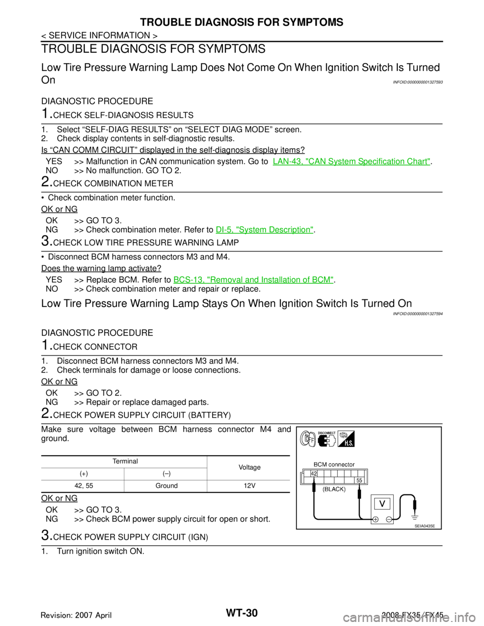
Make sure voltage between BCM harness connector M4 and
ground.
OK or NG
OK >> GO TO 3.
NG >> Check BCM power supply circuit for open or short.
3.CHECK POWER SUPPLY CIRCUIT (IGN)
1. Turn ignition switch ON.
Te r m i n a l Vol tag e
(+) (–)
42, 55 Ground 12V
SEIA0435E
3AA93ABC3ACD3AC03ACA3AC03AC63AC53A913A773A893A873A873A8E3A773A983AC73AC93AC03AC3
3A893A873A873A8F3A773A9D3AAF3A8A3A8C3A863A9D3AAF3A8B3A8C
Page 3872 of 3924
WT-32
< SERVICE INFORMATION >
TROUBLE DIAGNOSIS FOR SYMPTOMS
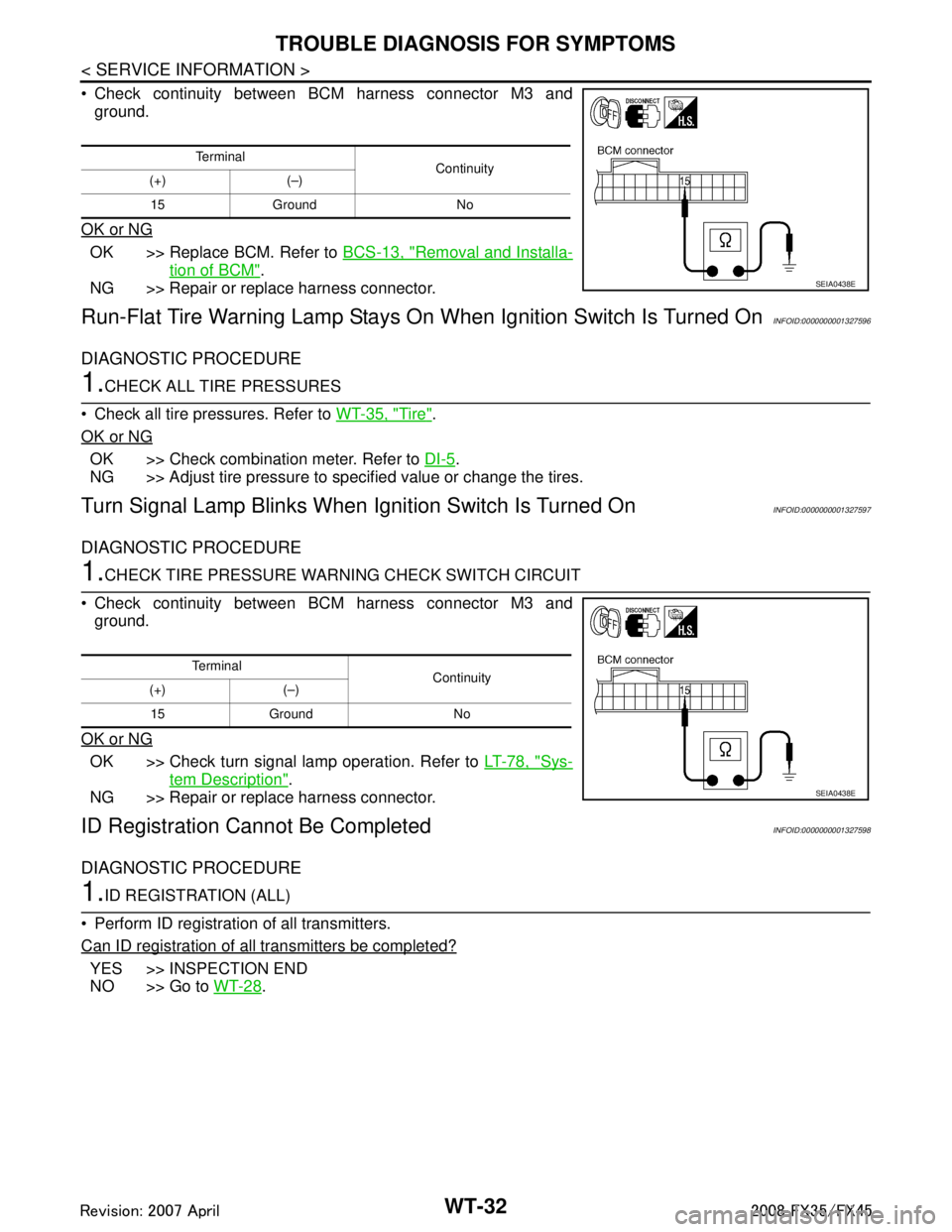
Check continuity between BCM harness connector M3 andground.
OK or NG
OK >> Replace BCM. Refer to BCS-13, "Removal and Installa-
tion of BCM".
NG >> Repair or replace harness connector.
Run-Flat Tire Warning Lamp Stays On When Ignition Switch Is Turned OnINFOID:0000000001327596
DIAGNOSTIC PROCEDURE
1.CHECK ALL TIRE PRESSURES
Check all tire pressures. Refer to WT-35, "
Tire".
OK or NG
OK >> Check combination meter. Refer to DI-5.
NG >> Adjust tire pressure to specified value or change the tires.
Turn Signal Lamp Blinks When Ignition Switch Is Turned OnINFOID:0000000001327597
DIAGNOSTIC PROCEDURE
1.CHECK TIRE PRESSURE WARNI NG CHECK SWITCH CIRCUIT
Check continuity between BCM harness connector M3 and ground.
OK or NG
OK >> Check turn signal lamp operation. Refer to LT-78, "Sys-
tem Description".
NG >> Repair or replace harness connector.
ID Registration Ca nnot Be CompletedINFOID:0000000001327598
DIAGNOSTIC PROCEDURE
1.ID REGISTRATION (ALL)
Perform ID registration of all transmitters.
Can ID registration of all transmitters be completed?
YES >> INSPECTION END
NO >> Go to WT-28
.
Te r m i n a l
Continuity
(+) (–)
15 Ground No
SEIA0438E
Te r m i n a l Continuity
(+) (–)
15 Ground No
SEIA0438E
3AA93ABC3ACD3AC03ACA3AC03AC63AC53A913A773A893A873A873A8E3A773A983AC73AC93AC03AC3
3A893A873A873A8F3A773A9D3AAF3A8A3A8C3A863A9D3AAF3A8B3A8C