2008 INFINITI FX35 sensor
[x] Cancel search: sensorPage 3698 of 3924
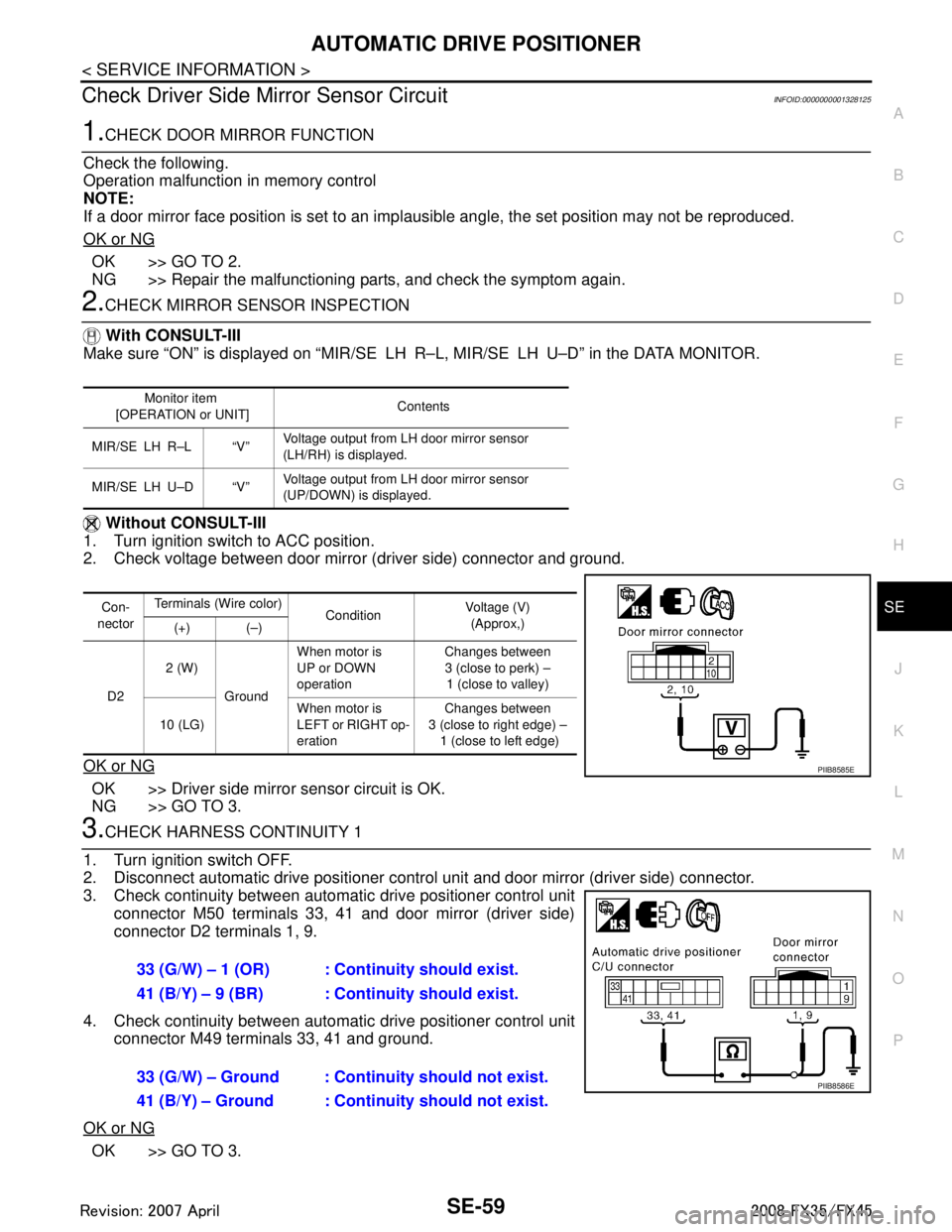
AUTOMATIC DRIVE POSITIONERSE-59
< SERVICE INFORMATION >
C
DE
F
G H
J
K L
M A
B
SE
N
O P
Check Driver Side Mirror Sensor CircuitINFOID:0000000001328125
1.CHECK DOOR MIRROR FUNCTION
Check the following.
Operation malfunction in memory control
NOTE:
If a door mirror face position is set to an impl ausible angle, the set position may not be reproduced.
OK or NG
OK >> GO TO 2.
NG >> Repair the malfunctioning parts, and check the symptom again.
2.CHECK MIRROR SENSOR INSPECTION
With CONSULT-III
Make sure “ON” is displayed on “MIR/SE L H R–L, MIR/SE LH U–D” in the DATA MONITOR.
Without CONSULT-III
1. Turn ignition switch to ACC position.
2. Check voltage between door mirror (driver side) connector and ground.
OK or NG
OK >> Driver side mirror sensor circuit is OK.
NG >> GO TO 3.
3.CHECK HARNESS CONTINUITY 1
1. Turn ignition switch OFF.
2. Disconnect automatic drive positioner control unit and door mirror (driver side) connector.
3. Check continuity between automat ic drive positioner control unit
connector M50 terminals 33, 41 and door mirror (driver side)
connector D2 terminals 1, 9.
4. Check continuity between automat ic drive positioner control unit
connector M49 terminals 33, 41 and ground.
OK or NG
OK >> GO TO 3.
Monitor item
[OPERATION or UNIT] Contents
MIR/SE LH R–L “V” Voltage output from LH door mirror sensor
(LH/RH) is displayed.
MIR/SE LH U–D “V” Voltage output from LH door mirror sensor
(UP/DOWN) is
displayed.
Con-
nector Terminals (Wire color)
ConditionVoltage (V)
(Approx,)
(+) (–)
D2 2 (W)
Ground When motor is
UP or DOWN
operation
Changes between
3 (close to perk) –
1 (close to valley)
10 (LG) When motor is
LEFT or RIGHT op-
eration Changes between
3 (close to right edge) – 1 (close to left edge)
PIIB8585E
33 (G/W) – 1 (OR) : Continuity should exist.
41 (B/Y) – 9 (BR) : Continuity should exist.
33 (G/W) – Ground : Continuity should not exist.
41 (B/Y) – Ground : Continuity should not exist.
PIIB8586E
3AA93ABC3ACD3AC03ACA3AC03AC63AC53A913A773A893A873A873A8E3A773A983AC73AC93AC03AC3
3A893A873A873A8F3A773A9D3AAF3A8A3A8C3A863A9D3AAF3A8B3A8C
Page 3699 of 3924
SE-60
< SERVICE INFORMATION >
AUTOMATIC DRIVE POSITIONER
NG >> Repair or replace harness between automatic drive positioner control unit and door mirror (driver
side).
4.CHECK HARNESS CONTINUITY 2
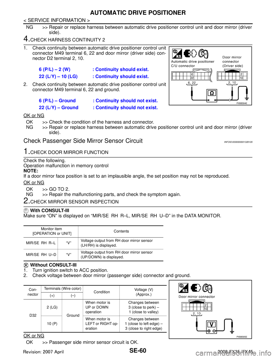
1. Check continuity between automat ic drive positioner control unit
connector M49 terminal 6, 22 and door mirror (driver side) con-
nector D2 terminal 2, 10.
2. Check continuity between automat ic drive positioner control unit
connector M49 terminal 6, 22 and ground.
OK or NG
OK >> Check the condition of the harness and connector.
NG >> Repair or replace harness between automatic dr ive positioner control unit and door mirror (driver
side).
Check Passenger Side Mi rror Sensor CircuitINFOID:0000000001328126
1.CHECK DOOR MIRROR FUNCTION
Check the following.
Operation malfunction in memory control
NOTE:
If a door mirror face position is set to an impl ausible angle, the set position may not be reproduced.
OK or NG
OK >> GO TO 2.
NG >> Repair the malfunctioning parts, and check the symptom again.
2.CHECK MIRROR SENSOR INSPECTION
With CONSULT-III
Make sure “ON” is displayed on “MIR/SE RH R–L, MIR/SE RH U–D” in the DATA MONITOR.
Without CONSULT-III
1. Turn ignition switch to ACC position.
2. Check voltage between door mirror (passenger side) connector and ground.
OK or NG
OK >> Passenger side mirror sensor circuit is OK. 6 (P/L) – 2 (W) : Cont
inuity should exist.
22 (L/Y) – 10 (LG) : Cont inuity should exist.
6 (P/L) – Ground : Continuity should not exist.
22 (L/Y) – Ground : Continuity should not exist.
PIIB8584E
Monitor item
[OPERATION or UNIT] Contents
MIR/SE RH R–L “V” Voltage output from RH door mirror sensor
(LH/RH) is displayed.
MIR/SE RH U–D “V” Voltage output from RH door mirror sensor
(UP/DOWN) is
displayed.
Con-
nector Terminals (W
ire color)
Condition Voltage (V)
(Approx.)
(+) (–)
D32 2 (LG)
GroundWhen motor is
UP or DOWN
operation
Changes between
3 (close to perk) – 1 (close to valley)
10 (P) When motor is
LEFT or RIGHT op-
eration Changes between
1 (close to left edge) – 3 (close to right edge)
PIIB8585E
3AA93ABC3ACD3AC03ACA3AC03AC63AC53A913A773A893A873A873A8E3A773A983AC73AC93AC03AC3
3A893A873A873A8F3A773A9D3AAF3A8A3A8C3A863A9D3AAF3A8B3A8C
Page 3700 of 3924
AUTOMATIC DRIVE POSITIONERSE-61
< SERVICE INFORMATION >
C
DE
F
G H
J
K L
M A
B
SE
N
O P
NG >> GO TO 3.
3.CHECK HARNESS CONTINUITY 1
1. Disconnect automatic drive positioner contro l unit and door mirror (passenger side) connector.
2. Check continuity between automat ic drive positioner control unit
connector M50 terminal 33, 41 and door mirror (passenger side)
connector D32 terminal 1, 9.
3. Check continuity between automat ic drive positioner control unit
connector M50 terminals 33, 41 and ground.
OK or NG
OK >> GO TO 3.
NG >> Repair or replace harness between automatic drive positioner control unit and door mirror (pas-
senger side).
4.CHECK HARNESS CONTINUITY 2
1. Check continuity between automat ic drive positioner control unit
connector M49 terminal 5, 21 and door mirror (passenger side)
connector D32 terminal 2, 10.
2. Check continuity between automat ic drive positioner control unit
connector M49 terminal 5, 21 and ground.
OK or NG
OK >> Check the condition of the harness and connector.
NG >> Repair or replace harness between automatic drive positioner control unit and door mirror (pas-
senger side).
Check Steering and Door Mirror Sensor Power Supp ly and Ground CircuitINFOID:0000000001328127
1.CHECK STEERING AND DOOR MIRROR SENSOR POWER SUPPLY
1. Turn ignition switch OFF.
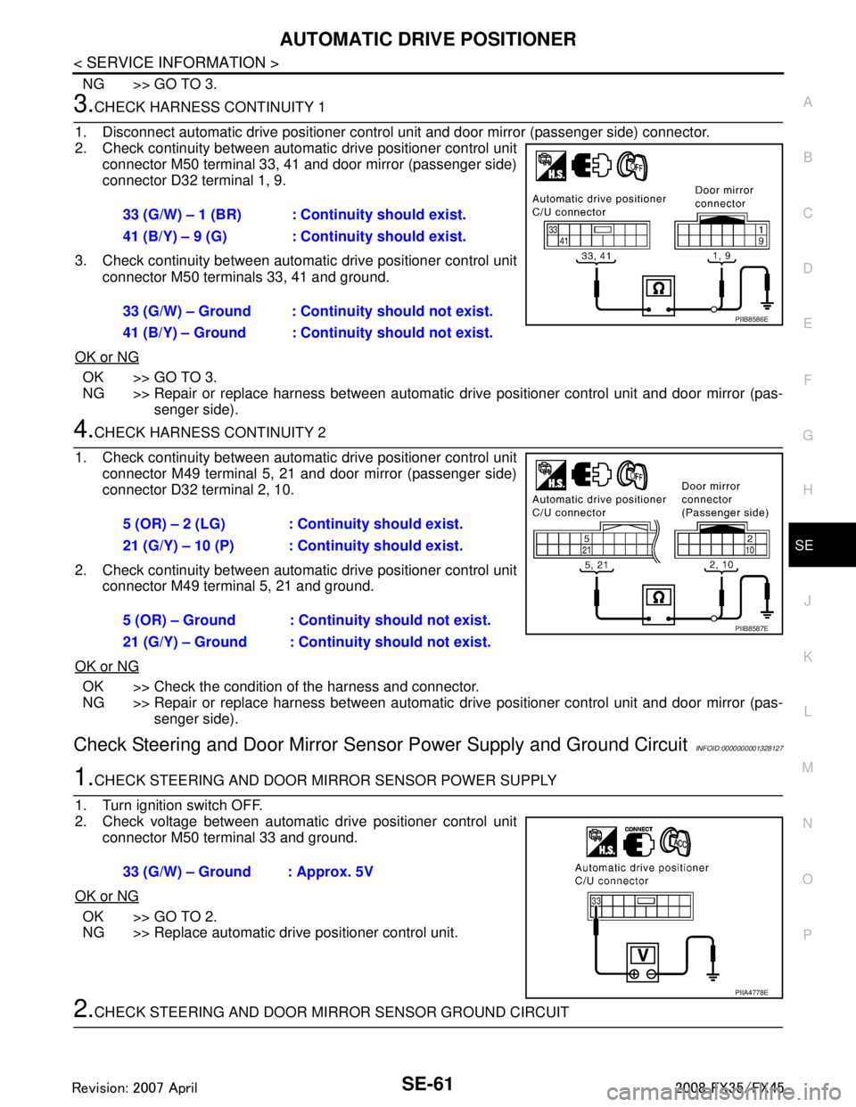
2. Check voltage between automatic drive positioner control unit
connector M50 terminal 33 and ground.
OK or NG
OK >> GO TO 2.
NG >> Replace automatic drive positioner control unit.
2.CHECK STEERING AND DOOR MIRROR SENSOR GROUND CIRCUIT
33 (G/W) – 1 (BR) : Continuity should exist.
41 (B/Y) – 9 (G) : Continuity should exist.
33 (G/W) – Ground : Continuity should not exist.
41 (B/Y) – Ground : Continuity should not exist.
PIIB8586E
5 (OR) – 2 (LG) : Continuity should exist.
21 (G/Y) – 10 (P) : Cont
inuity should exist.
5 (OR) – Ground : Continuity should not exist.
21 (G/Y) – Ground : Contin uity should not exist.
PIIB8587E
33 (G/W) – Ground : Approx. 5V
PIIA4778E
3AA93ABC3ACD3AC03ACA3AC03AC63AC53A913A773A893A873A873A8E3A773A983AC73AC93AC03AC3
3A893A873A873A8F3A773A9D3AAF3A8A3A8C3A863A9D3AAF3A8B3A8C
Page 3701 of 3924
SE-62
< SERVICE INFORMATION >
AUTOMATIC DRIVE POSITIONER
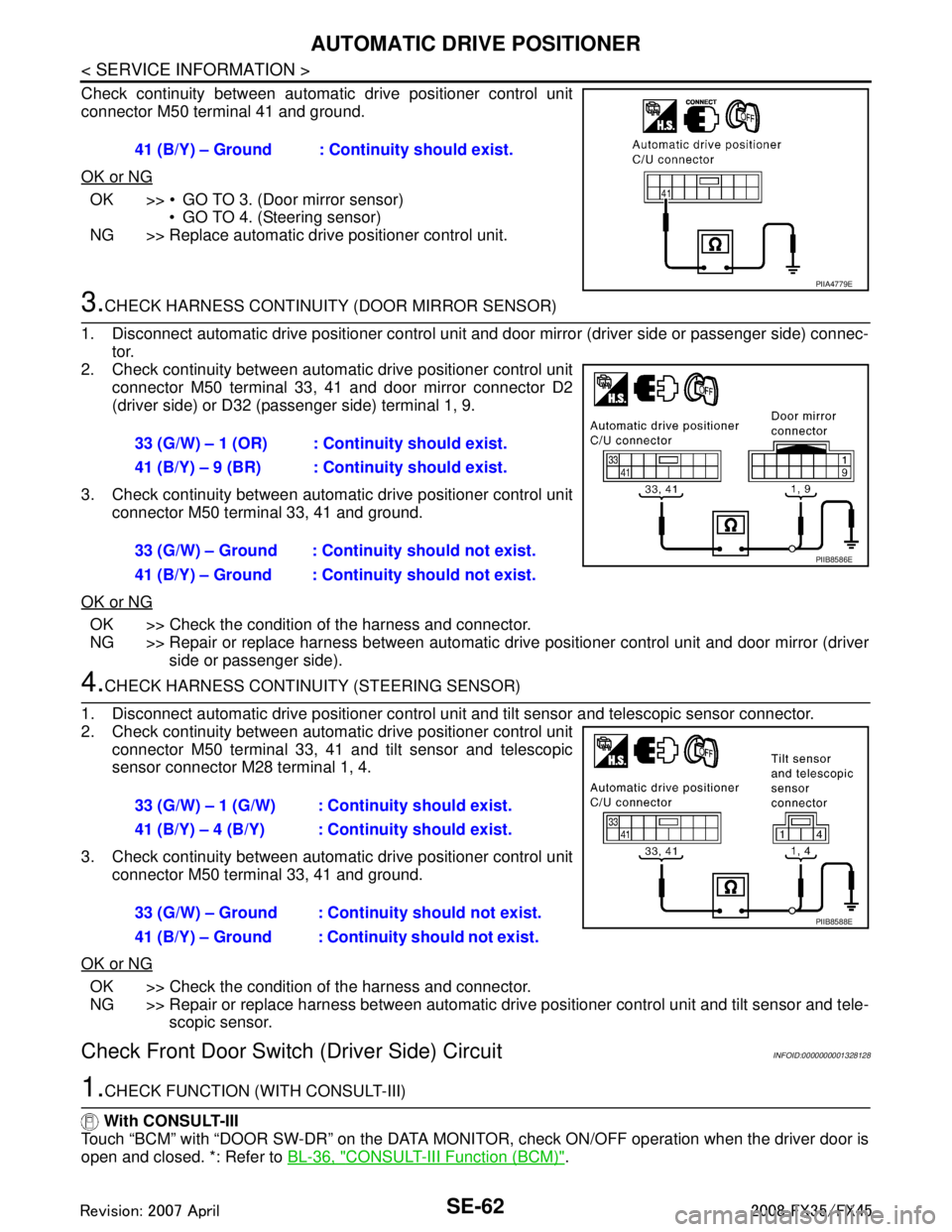
Check continuity between automatic drive positioner control unit
connector M50 terminal 41 and ground.
OK or NG
OK >> GO TO 3. (Door mirror sensor) GO TO 4. (Steering sensor)
NG >> Replace automatic drive positioner control unit.
3.CHECK HARNESS CONTINUITY (DOOR MIRROR SENSOR)
1. Disconnect automatic drive positioner control unit and door mirror (driver side or passenger side) connec-
tor.
2. Check continuity between automat ic drive positioner control unit
connector M50 terminal 33, 41 and door mirror connector D2
(driver side) or D32 (passenger side) terminal 1, 9.
3. Check continuity between automat ic drive positioner control unit
connector M50 terminal 33, 41 and ground.
OK or NG
OK >> Check the condition of the harness and connector.
NG >> Repair or replace harness between automatic dr ive positioner control unit and door mirror (driver
side or passenger side).
4.CHECK HARNESS CONTINUI TY (STEERING SENSOR)
1. Disconnect automatic drive positioner control uni t and tilt sensor and telescopic sensor connector.
2. Check continuity between automat ic drive positioner control unit
connector M50 terminal 33, 41 and tilt sensor and telescopic
sensor connector M28 terminal 1, 4.
3. Check continuity between automat ic drive positioner control unit
connector M50 terminal 33, 41 and ground.
OK or NG
OK >> Check the condition of the harness and connector.
NG >> Repair or replace harness between automatic driv e positioner control unit and tilt sensor and tele-
scopic sensor.
Check Front Door Switch (Driver Side) CircuitINFOID:0000000001328128
1.CHECK FUNCTION (WITH CONSULT-III)
With CONSULT-III
Touch “BCM” with “DOOR SW-DR” on the DATA MONITO R, check ON/OFF operation when the driver door is
open and closed. *: Refer to BL-36, "
CONSULT-III Function (BCM)".
41 (B/Y) – Ground : Cont
inuity should exist.
PIIA4779E
33 (G/W) – 1 (OR) : Continuity should exist.
41 (B/Y) – 9 (BR) : Continuity should exist.
33 (G/W) – Ground : Contin uity should not exist.
41 (B/Y) – Ground : Contin uity should not exist.
PIIB8586E
33 (G/W) – 1 (G/W) : Continuity should exist.
41 (B/Y) – 4 (B/Y) : Continuity should exist.
33 (G/W) – Ground : Continuity should not exist.
41 (B/Y) – Ground : Continuity should not exist.
PIIB8588E
3AA93ABC3ACD3AC03ACA3AC03AC63AC53A913A773A893A873A873A8E3A773A983AC73AC93AC03AC3
3A893A873A873A8F3A773A9D3AAF3A8A3A8C3A863A9D3AAF3A8B3A8C
Page 3738 of 3924
SRS-1
RESTRAINTS
C
DE
F
G
I
J
K L
M
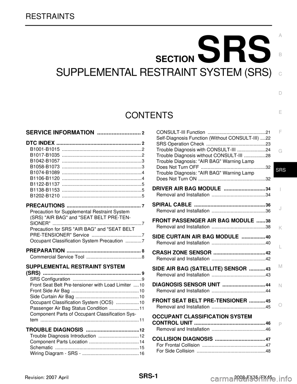
SECTION SRS
A
B
SRS
N
O P
CONTENTS
SUPPLEMENTAL RESTRAINT SYSTEM (SRS)
SERVICE INFORMATION .. ..........................2
DTC INDEX ..................................................... .....2
B1001-B1015 ...................................................... ......2
B1017-B1035 ............................................................2
B1042-B1057 ............................................................3
B1058-B1073 ............................................................3
B1074-B1089 ............................................................4
B1106-B1120 ............................................................4
B1122-B1137 ............................................................5
B1138-B1153 ............................................................5
B1202-B1210 ............................................................5
PRECAUTIONS ...................................................7
Precaution for Supplemental Restraint System
(SRS) "AIR BAG" and "SEAT BELT PRE-TEN-
SIONER" ............................................................. ......
7
Precaution for SRS "AIR BAG" and "SEAT BELT
PRE-TENSIONER" Service ......................................
7
Occupant Classification System Precaution .............7
PREPARATION ...................................................8
Commercial Service Tool .................................... ......8
SUPPLEMENTAL RESTRAINT SYSTEM
(SRS) ...................................................................
9
SRS Configuration .............................................. ......9
Front Seat Belt Pre-tensioner with Load Limiter .....10
Front Side Air Bag ...................................................10
Side Curtain Air Bag ................................................10
Occupant Classification System (OCS) ..................10
Passenger Air Bag Status Condition .......................11
Component Parts of Occupant Classification Sys-
tem ..........................................................................
11
TROUBLE DIAGNOSIS .....................................12
Trouble Diagnosis Introduction ........................... ....12
Component Parts Location ......................................14
Schematic ...............................................................15
Wiring Diagram - SRS - ...........................................16
CONSULT-III Function ........................................
....21
Self-Diagnosis Function (Without CONSULT-III) .....22
SRS Operation Check .............................................23
Trouble Diagnosis with CONSULT-III ......................24
Trouble Diagnosis without CONSULT-III .................28
Trouble Diagnosis: "AIR BAG" Warning Lamp
Does Not Turn OFF .................................................
32
Trouble Diagnosis: "AIR BAG" Warning Lamp
Does Not Turn ON ...................................................
32
DRIVER AIR BAG MODULE ............................34
Removal and Installation .........................................34
SPIRAL CABLE ................................................36
Removal and Installation .........................................36
FRONT PASSENGER AIR BAG MODULE ......38
Removal and Installation .........................................38
SIDE CURTAIN AIR BAG MODULE ................40
Removal and Installation .........................................40
CRASH ZONE SENSOR ...................................42
Removal and Installation ..................................... ....42
SIDE AIR BAG (SATELLITE) SENSOR ...........43
Removal and Installation .........................................43
DIAGNOSIS SENSOR UNIT .............................44
Removal and Installation .........................................44
FRONT SEAT BELT PRE-TENSIONER ...........45
Removal and Installation .........................................45
OCCUPANT CLASSIFICATION SYSTEM
CONTROL UNIT ................................................
46
Removal and Installation .........................................46
COLLISION DIAGNOSIS ..................................47
For Frontal Collision ................................................47
For Side Collision ....................................................48
3AA93ABC3ACD3AC03ACA3AC03AC63AC53A913A773A893A873A873A8E3A773A983AC73AC93AC03AC3
3A893A873A873A8F3A773A9D3AAF3A8A3A8C3A863A9D3AAF3A8B3A8C
Page 3739 of 3924
SRS-2
< SERVICE INFORMATION >
DTC INDEX
SERVICE INFORMATION
DTC INDEX
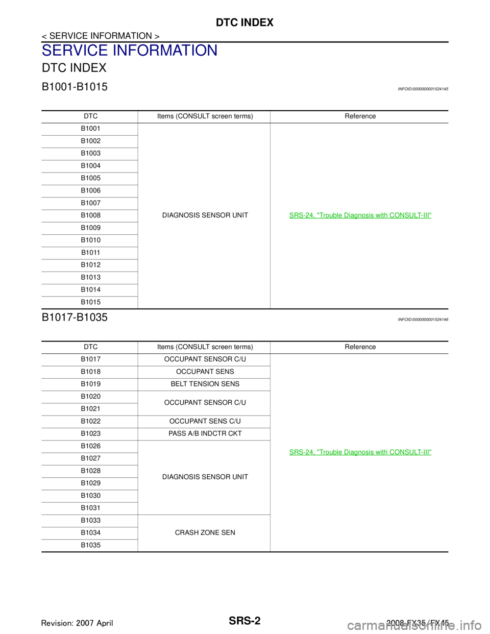
B1001-B1015INFOID:0000000001524145
B1017-B1035INFOID:0000000001524146
DTC Items (CONSULT screen terms) Reference
B1001
DIAGNOSIS SENSOR UNIT SRS-24, "
Trouble Diagnosis with CONSULT-III"
B1002
B1003
B1004
B1005
B1006
B1007
B1008
B1009
B1010
B1011
B1012
B1013
B1014
B1015
DTC Items (CONSULT sc reen terms) Reference
B1017 OCCUPANT SENSOR C/U
SRS-24, "
Trouble Diagnosis with CONSULT-III"
B1018 OCCUPANT SENS
B1019 BELT TENSION SENS
B1020OCCUPANT SENSOR C/U
B1021
B1022 OCCUPANT SENS C/U
B1023 PASS A/B INDCTR CKT
B1026
DIAGNOSIS SENSOR UNIT
B1027
B1028
B1029
B1030
B1031
B1033
CRASH ZONE SEN
B1034
B1035
3AA93ABC3ACD3AC03ACA3AC03AC63AC53A913A773A893A873A873A8E3A773A983AC73AC93AC03AC3
3A893A873A873A8F3A773A9D3AAF3A8A3A8C3A863A9D3AAF3A8B3A8C
Page 3740 of 3924
DTC INDEXSRS-3
< SERVICE INFORMATION >
C
DE
F
G
I
J
K L
M A
B
SRS
N
O P
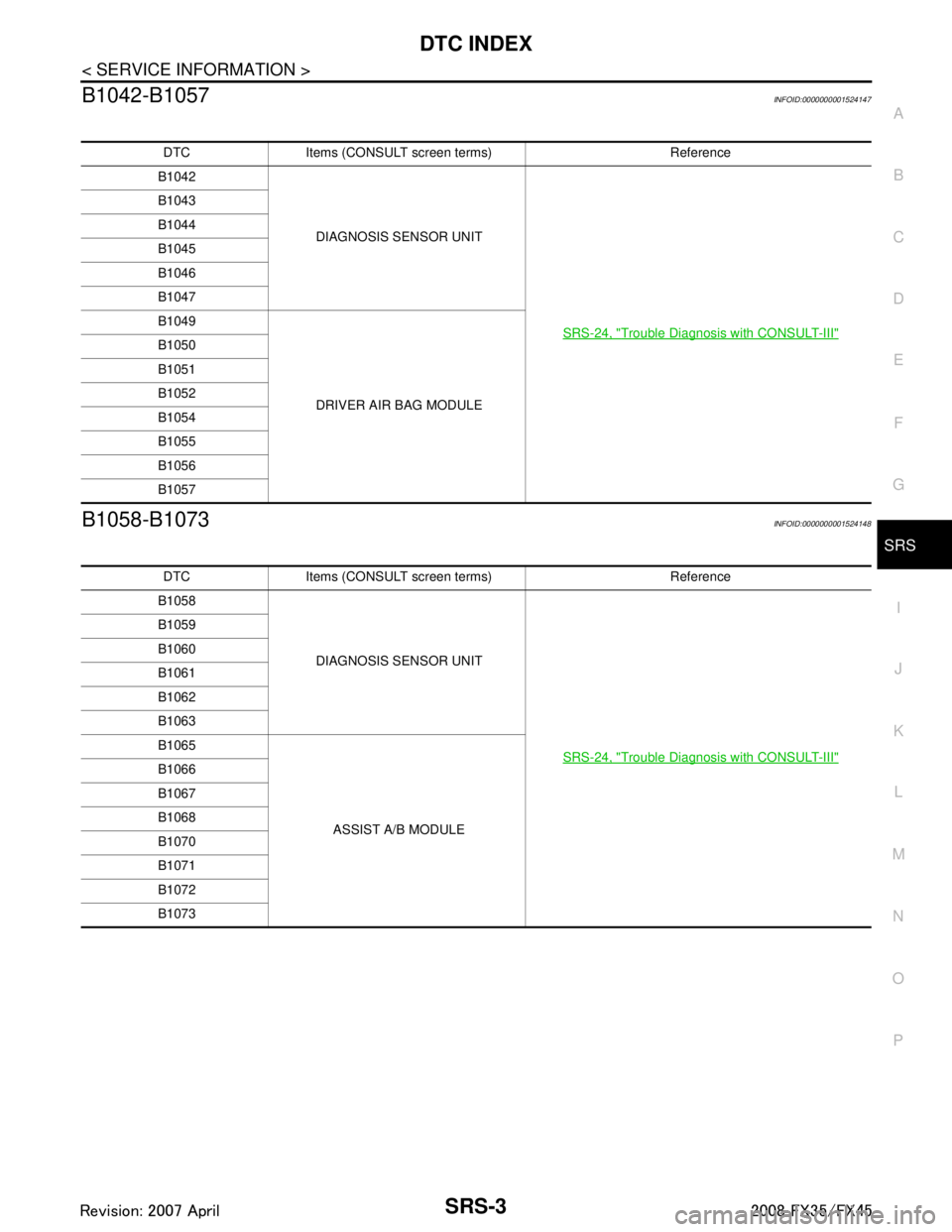
B1042-B1057INFOID:0000000001524147
B1058-B1073INFOID:0000000001524148
DTC Items (CONSULT screen terms) Reference
B1042
DIAGNOSIS SENSOR UNIT
SRS-24, "
Trouble Diagnosis with CONSULT-III"
B1043
B1044
B1045
B1046
B1047
B1049DRIVER AIR BAG MODULE
B1050
B1051
B1052
B1054
B1055
B1056
B1057
DTC Items (CONSULT screen terms) Reference
B1058
DIAGNOSIS SENSOR UNIT
SRS-24, "
Trouble Diagnosis with CONSULT-III"
B1059
B1060
B1061
B1062
B1063
B1065ASSIST A/B MODULE
B1066
B1067
B1068
B1070
B1071
B1072
B1073
3AA93ABC3ACD3AC03ACA3AC03AC63AC53A913A773A893A873A873A8E3A773A983AC73AC93AC03AC3
3A893A873A873A8F3A773A9D3AAF3A8A3A8C3A863A9D3AAF3A8B3A8C
Page 3741 of 3924
SRS-4
< SERVICE INFORMATION >
DTC INDEX
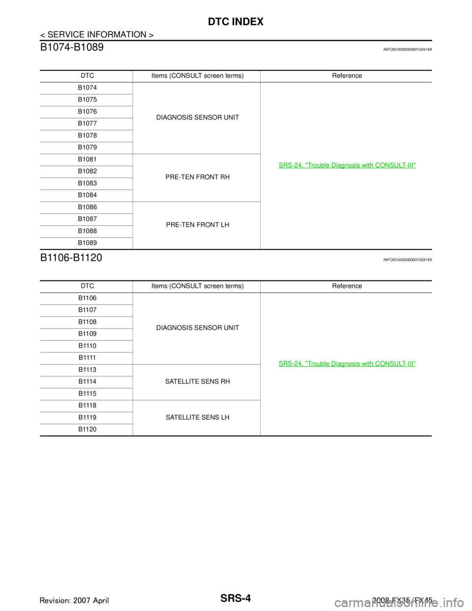
B1074-B1089
INFOID:0000000001524149
B1106-B1120INFOID:0000000001524150
DTC Items (CONSULT sc reen terms) Reference
B1074
DIAGNOSIS SENSOR UNIT
SRS-24, "
Trouble Diagnosis with CONSULT-III"
B1075
B1076
B1077
B1078
B1079
B1081PRE-TEN FRONT RH
B1082
B1083
B1084
B1086
PRE-TEN FRONT LH
B1087
B1088
B1089
DTC Items (CONSULT sc
reen terms) Reference
B1106
DIAGNOSIS SENSOR UNIT
SRS-24, "
Trouble Diagnosis with CONSULT-III"
B1107
B1108
B1109B 111 0B 1111
B 111 3 SATELLITE SENS RH
B 111 4
B 111 5
B 111 8
SATELLITE SENS LH
B 111 9
B1120
3AA93ABC3ACD3AC03ACA3AC03AC63AC53A913A773A893A873A873A8E3A773A983AC73AC93AC03AC3
3A893A873A873A8F3A773A9D3AAF3A8A3A8C3A863A9D3AAF3A8B3A8C