2008 INFINITI FX35 sensor
[x] Cancel search: sensorPage 3651 of 3924

SE-12
< SERVICE INFORMATION >
AUTOMATIC DRIVE POSITIONER
AUTOMATIC DRIVE POSITIONER
System DescriptionINFOID:0000000001328097
The system automatically moves the driver seat to facilitate entry/exit to/from the vehicle. The automatic
drive positioner control unit can also store the optimum driving positions (driver seat, steering wheel position
(tilt, telescopic) and door mirror position) for 2 people. If the driver is changes, one-touch operation allows
changing to the other driving position.
The settings (ON/OFF) of the automatic sliding s eat (Entry/Exiting operation) at entry/exit can be changed
as desired, using the display unit in the center of the instrument panel. The set content is transmitted by
CAN communication, from display contro l unit to driver seat control unit.
Using CONSULT-III, the seat slide and steering wheel amount at entry/exit setting can be changed.
MANUAL OPERATION
The driving position [seat position, steering wheel posit ion (tilt, telescopic) and door mirror position] can be
adjusted with the power seat switch or ADP steering switch or door mirror remote control switch.
NOTE:
The seat can be manually operated with the ignition switch OFF.
The door mirrors can be manually operated with the ignition switch turned ACC or ON.
AUTOMATIC OPERATION
NOTE:
Disconnecting the battery erases the stored memory.
After connecting the battery, insert the key into the ignition cylinder and turn the driver door switch ON (open) →OFF (close) →ON
(open), the Entry/ Exiting operation becomes possible.
After exiting operation is carried out, return operation can be operated.
NOTE:
During automatic operation, if the ignition switch is turned ON →START, the automatic operation is suspended. When the ignition switch
returns to ON, it resumes.
MEMORY STORING AND KEYFOB INTERLOCK STORING
Store the 2 driving positions and shifts to t he stored driving position with the memory switch.
Function Description
Memory switch operation The seat, steering and door mirror move to the stored driving position by pushing
memory switch (1 or 2).
Entry/Exiting function Exiting operation At exit, the seat moves backward and steering wheel moves forward/upward.
Entry operation
At entry, the seat and steering wheel returns from the exiting position to the previous
driving position.
keyfob interlock operation Perform memory operation, exiting operation and entry operation by pressing keyfob
unlock button.
Auto operation temporary stop
conditions. When ignition switch turned to START during memory switch operation and return opera-
tion, memory switch operation and entry operation is stopped.
Auto operation stop conditions. When the vehicle speed becomes 7 km/h (4 MPH) or higher.
When the setting switch, memory switch 1, or 2 are pressed.
When A/T selector lever is in any position other than P.
When the door mirror remote control switch is operated (when ignition switch turned to
ON or ACC).
When power seat switch turned ON.
When ADP steering switch turned ON (telescopic operation or tilt operation).
When door mirror operates (only memory switch operation).
When driver seat sliding Entry/Exiting setting is OFF (only entry/exiting operation).
When steering wheel tilt and telescopic Entry/Exiting setting is OFF (only entry/exiting op-
eration).
When the tilt and telescopic sensor malfunction is detected.
3AA93ABC3ACD3AC03ACA3AC03AC63AC53A913A773A893A873A873A8E3A773A983AC73AC93AC03AC3
3A893A873A873A8F3A773A9D3AAF3A8A3A8C3A863A9D3AAF3A8B3A8C
Page 3656 of 3924
AUTOMATIC DRIVE POSITIONERSE-17
< SERVICE INFORMATION >
C
DE
F
G H
J
K L
M A
B
SE
N
O P
CAN Communication System DescriptionINFOID:0000000001328099
CAN (Controller Area Network) is a serial communication li ne for real time application. It is an on-vehicle mul-
tiplex communication line with high data communication speed and excellent error detection ability. Many elec-
tronic control units are equipped onto a vehicle, and each control unit shares information and links with other
control units during operation (not independent). In CAN communication, control units are connected with 2
communication lines (CAN H line, CAN L line) allowing a high rate of information transmission with less wiring.
Each control unit transmits/receives data but selectively reads required data only.
CAN Communication UnitINFOID:0000000001328100
Refer to LAN-43, "CAN System Specification Chart".
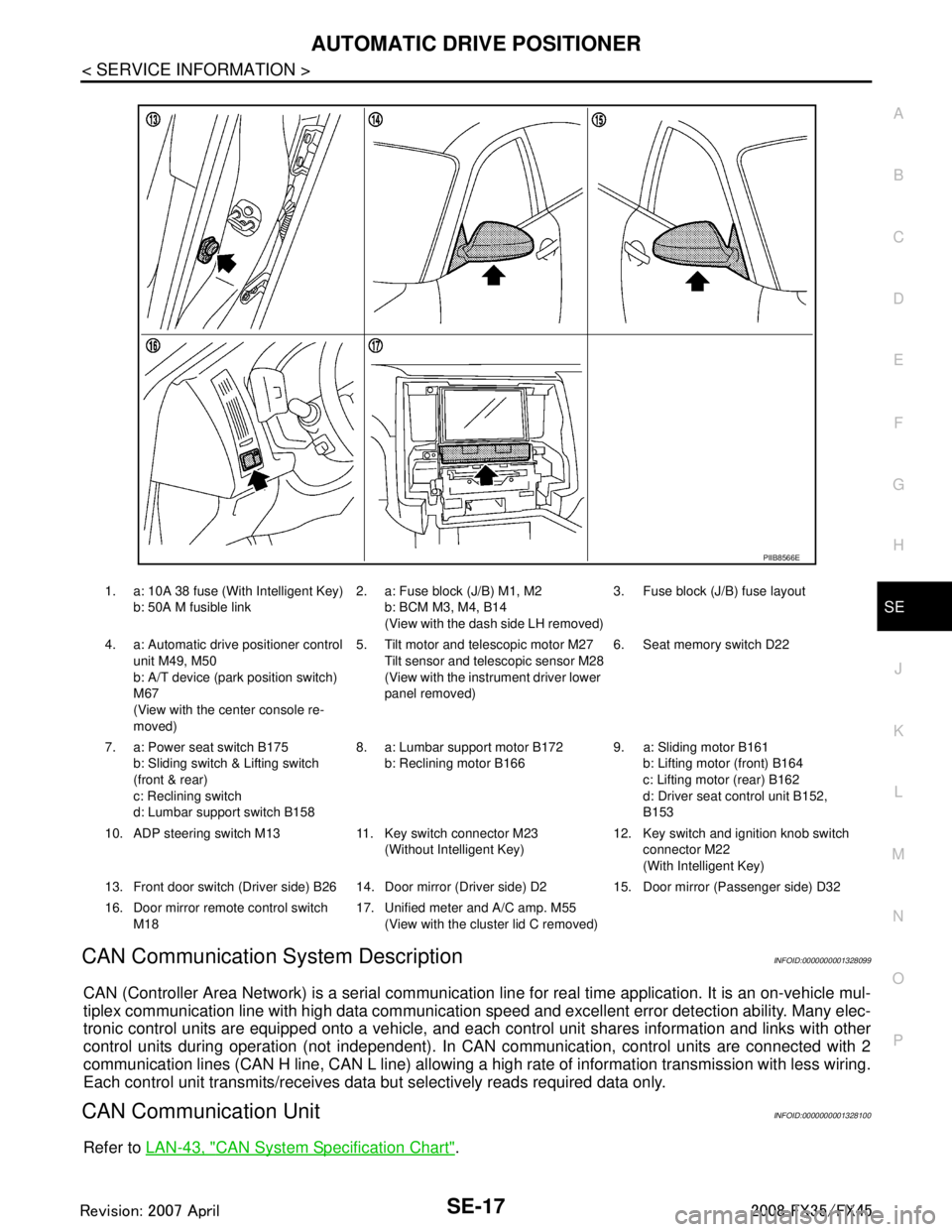
1. a: 10A 38 fuse (With Intelligent Key)
b: 50A M fusible link 2. a: Fuse block (J/B) M1, M2
b: BCM M3, M4, B14
(View with the dash side LH removed) 3. Fuse block (J/B) fuse layout
4. a: Automatic drive positioner control unit M49, M50
b: A/T device (park position switch)
M67
(View with the center console re-
moved) 5. Tilt motor and telescopic motor M27
Tilt sensor and telescopic sensor M28
(View with the instrument driver lower
panel removed) 6. Seat memory switch D22
7. a: Power seat switch B175 b: Sliding switch & Lifting switch
(front & rear)
c: Reclining switch
d: Lumbar support switch B158 8. a: Lumbar support motor B172
b: Reclining motor B166 9. a: Sliding motor B161
b: Lifting motor (front) B164
c: Lifting motor (rear) B162
d: Driver seat control unit B152,
B153
10. ADP steering switch M13 11. Key switch connector M23 (Without Intelligent Key)12. Key switch and ignition knob switch
connector M22
(With Intelligent Key)
13. Front door switch (Driver side) B26 14. Door mirro r (Driver side) D2 15. Door mirror (Passenger side) D32
16. Door mirror remote control switch M18 17. Unified meter and A/C amp. M55
(View with the clus ter lid C removed)
PIIB8566E
3AA93ABC3ACD3AC03ACA3AC03AC63AC53A913A773A893A873A873A8E3A773A983AC73AC93AC03AC3
3A893A873A873A8F3A773A9D3AAF3A8A3A8C3A863A9D3AAF3A8B3A8C
Page 3671 of 3924

SE-32
< SERVICE INFORMATION >
AUTOMATIC DRIVE POSITIONER
Terminal and Reference Value for BCM
INFOID:0000000001328103
Terminal and Reference Value for Auto matic Drive Positioner Control UnitINFOID:0000000001328104
Te r -
minal Wire
Color Item Signal
Input/Output Condition Voltage (V)
(Approx.)
11 LG Ignition switch (ACC) Input Ignition switch
(ACC or ON position)
Battery voltage
37 B/W Key switch signal Input Key switch ON (key is inserted in
ignition key cylinder)
Battery voltage
Key switch OFF (key is removed
from ignition key cylinder) 0
38 W/L Ignition switch (ON) Input Ignition switch
(ON or START position)
Battery voltage
39 L CAN-H Input/Output — —
40 P CAN-L Input/Output — —
42 L/R Power source (Fuse) Input — Battery voltage
49 B Ground (signal) — — 0
52 B Ground (power) — — 0
55 G Power supply (Fusible link) Input — Battery voltage
62 W Front door switch
(driver side)
Output ON (Open)
→ OFF (Closed) 0 → Battery voltage
Te r -
minal Wire
Color Item Signal
Input/Output Condition Voltage (V)
(Approx.)
1 R Tilt switch UP signal Input Tilt switch turned to upward 0
Other than above 5
2 G/W Changeover switch RH signal Input When changeover switch in RH
position
0
Other than above 5
3 GY Mirror switch UP signal Input When mirror switch in turned to up-
ward position
0
Other than above 5
4 Y Mirror switch LEFT signal Input When mirror switch in turned to
leftward position
0
Other than above 5
5OR Passenger side mirror sensor
(vertical) signal Input
When passenger si
de mirror motor
is UP or DOWN operation Changes between 3 (close to
perk) - 1 (close to valley)
6P/L Driver side mirror sensor
(vertical) signal InputWhen driver side mirror motor is
UP or DOWN operation Changes between 3 (close to
perk) - 1 (close to valley)
7 Y/R Tilt sensor signal Input Tilt position, top 2
Tilt position, bottom 4
10 B UART LINE (TX) Output Memory switch 1 or 2 operated
PIIA4813E
3AA93ABC3ACD3AC03ACA3AC03AC63AC53A913A773A893A873A873A8E3A773A983AC73AC93AC03AC3
3A893A873A873A8F3A773A9D3AAF3A8A3A8C3A863A9D3AAF3A8B3A8C
Page 3672 of 3924
AUTOMATIC DRIVE POSITIONERSE-33
< SERVICE INFORMATION >
C
DE
F
G H
J
K L
M A
B
SE
N
O P
11 B R Telescopic switch
FORWARD signal
InputTelescopic switch turned to for-
ward
0
Other than above 5
14 L/W Passenger side
mirror motor
UP signal OutputWhen passenger si
de mirror motor
UP operation 1.5 - Battery voltage
Other than above 0
15 L/B Passenger side
mirror motor
LEFT signal OutputWhen passenger si
de mirror motor
LEFT operation 1.5 - Battery voltage
Other than above 0
16 P Driver side mirror motor
DOWN signal
OutputWhen driver side mirror motor
DOWN operation
1.5 - Battery voltage
Other than above 0
Driver side mirror motor
RIGTH signal When driver side mirror motor
RIGHT operation
1.5 - Battery voltage
Other than above 0
17 R/B Tilt switch DOWN signal Input Tilt switch turned to downward 0
Other than above 5
18 L/OR Changeover switch LH signal Input When changeover switch in LH po-
sition
0
Other than above 5
19 GY/L Mirror switch DOWN signal Input When mirror switch
in turned to
downward position 0
Other than above 5
20 PU Mirror switch RIGHT signal Input When mirror switch
in turned to
rightward position 0
Other than above 5
21 G/Y Passenger side
mirror sensor
(horizontal) signal InputWhen passenger si
de mirror motor
is LEFT or RIGHT operation Changes between 1 (close to left
edge) - 3 (close to right edge)
22 L/Y Driver side mirror sensor
(horizontal) signal
InputWhen driver side
mirror motor is
LEFT or RIGHT operation Changes between 1 (close to
right edge) - 3 (close to left edge)
23 Y/B Telescopic sensor signal Input Telescopic position, top 1
Telescopic position, bottom 4
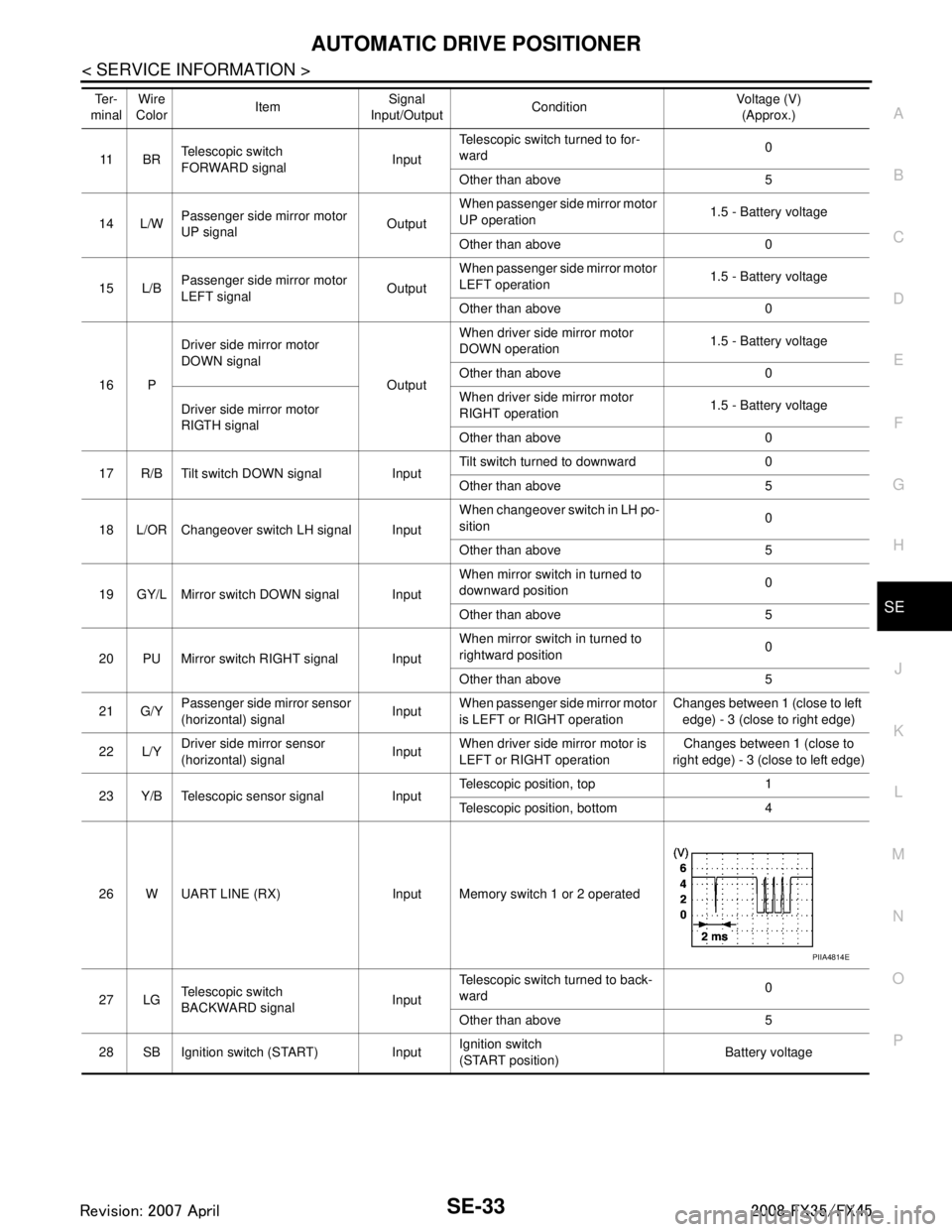
26 W UART LINE (RX) Input Memory switch 1 or 2 operated
27 LG Telescopic switch
BACKWARD signal InputTelescopic switch turned to back-
ward
0
Other than above 5
28 SB Ignition switch (START) Input Ignition switch
(START position)
Battery voltage
Te r -
minal Wire
Color
Item Signal
Input/Output Condition Voltage (V)
(Approx.)
PIIA4814E
3AA93ABC3ACD3AC03ACA3AC03AC63AC53A913A773A893A873A873A8E3A773A983AC73AC93AC03AC3
3A893A873A873A8F3A773A9D3AAF3A8A3A8C3A863A9D3AAF3A8B3A8C
Page 3673 of 3924
SE-34
< SERVICE INFORMATION >
AUTOMATIC DRIVE POSITIONER
Terminal and Reference Value for Driver Seat Control Unit
INFOID:0000000001328105
30 W/RPassenger side
mirror motor
DOWN signal
OutputWhen passenger si
de mirror motor
downward 1.5 - Battery voltage
Other than above 0
Passenger side mirror motor
RIGTH signal When passenger si
de mirror motor
RIGHT operation 1.5 - Battery voltage
Other than above 0
31 R/W Driver side mirror motor
UP signal OutputWhen driver side mirror motor up-
ward
1.5 - Battery voltage
Other than above 0
32 G/B Driver side mirror motor
LEFT signal
OutputWhen driver side mirror motor
LEFT operation
1.5 - Battery voltage
Other than above 0
33 G/W Sensor power supply Input — 5
34 L/R Battery power supply Input — Battery voltage
35 R/L Tilt motor UP signal Output Tilt switch turned to upward Battery voltage
Other than above 0
36 L/R Telescopic motor
FORWARD signal OutputTelescopic switch turned to for-
ward
Battery voltage
OFF 0
39 W/R Battery power supply Input — Battery voltage
40 B Ground (signal) — — 0
41 B/Y Ground (sensor) — — 0
42 R/B Tilt motor DOWN signal Output Tilt switch turned to downward Battery voltage
Other than above 0
44 L/W Telescopic motor
BACKWARD signal OutputTelescopic switch turned to back-
ward
Battery voltage
Other than above 0
48 B Ground (power) — — 0
Te r -
minal Wire
Color Item Signal
Input/Output Condition Voltage (V)
(Approx.)
Te r -
minal Wire
Color ItemSignal Input/
Output Condition Voltage (V)
(Approx.)
1A R Power source (Fusible link) Input — Battery voltage
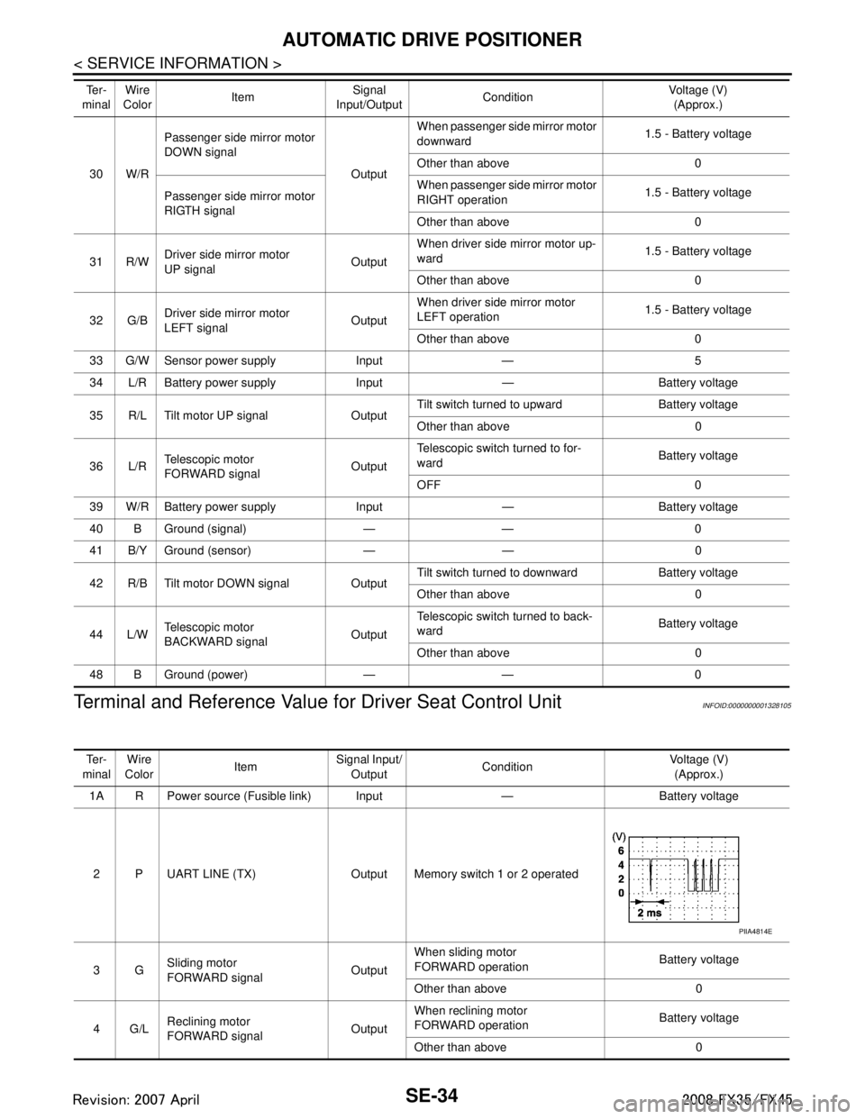
2 P UART LINE (TX) Output Memory switch 1 or 2 operated
3G Sliding motor
FORWARD signal OutputWhen sliding motor
FORWARD operation
Battery voltage
Other than above 0
4G/L Reclining motor
FORWARD signal OutputWhen reclining motor
FORWARD operation
Battery voltage
Other than above 0
PIIA4814E
3AA93ABC3ACD3AC03ACA3AC03AC63AC53A913A773A893A873A873A8E3A773A983AC73AC93AC03AC3
3A893A873A873A8F3A773A9D3AAF3A8A3A8C3A863A9D3AAF3A8B3A8C
Page 3674 of 3924
AUTOMATIC DRIVE POSITIONERSE-35
< SERVICE INFORMATION >
C
DE
F
G H
J
K L
M A
B
SE
N
O P
5LG Front lifting motor
DOWN signal
OutputWhen front lifting motor
DOWN operation
Battery voltage
Other than above 0
6 G/W Rear lifting motor UP signal Output When rear lifting motor
UP operation
Battery voltage
Other than above 0
7G/B Rear lifting motor
DOWN signal OutputWhen rear lifting motor
DOWN operation
Battery voltage
Other than above 0
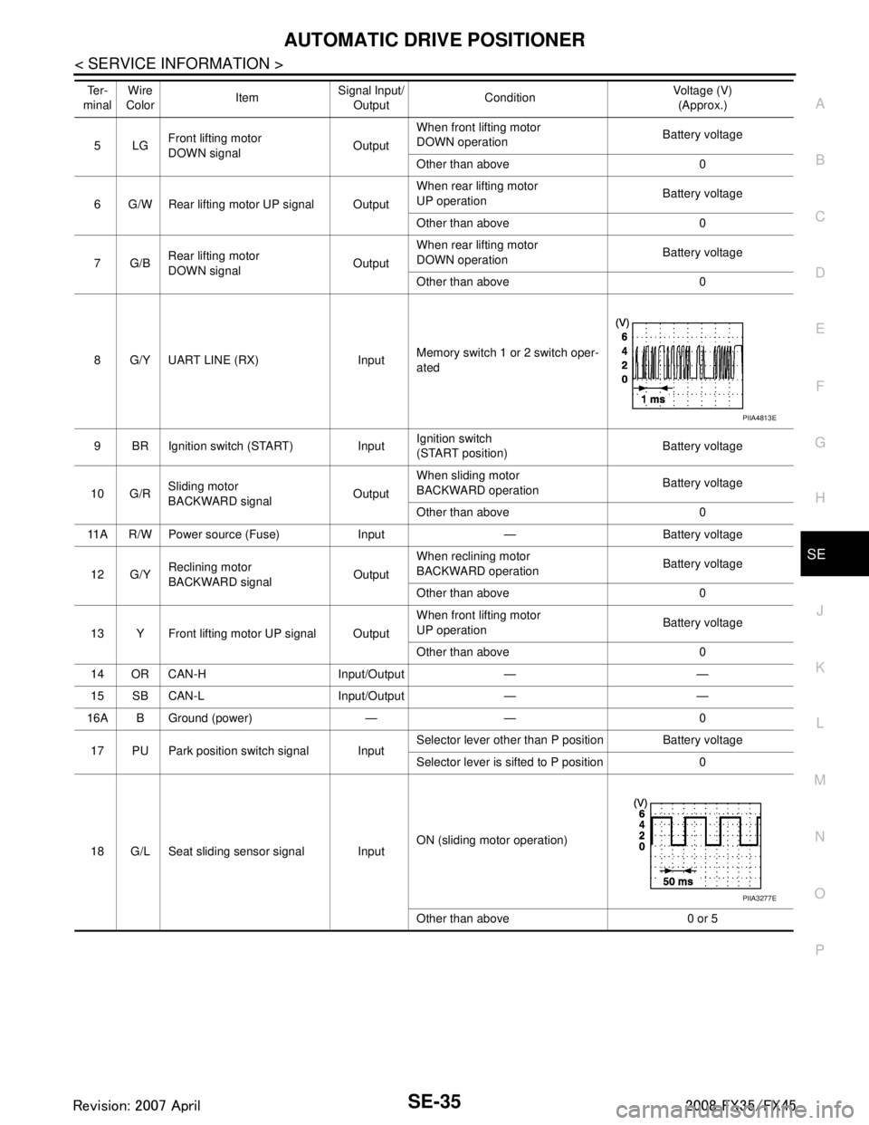
8 G/Y UART LINE (RX) Input Memory switch 1 or 2 switch oper-
ated
9 BR Ignition switch (START) Input Ignition switch
(START position)Battery voltage
10 G/R Sliding motor
BACKWARD signal
OutputWhen sliding motor
BACKWARD operation
Battery voltage
Other than above 0
11A R/W Power source (Fuse) Input — Battery voltage
12 G/Y Reclining motor
BACKWARD signal OutputWhen reclining motor
BACKWARD operation
Battery voltage
Other than above 0
13 Y Front lifting motor UP signal Output When front lifting motor
UP operation
Battery voltage
Other than above 0
14 OR CAN-H Input/Output — —
15 SB CAN-L Input/Output — —
16A B Ground (power) — — 0
17 PU Park position switch signal Input Selector lever other than P position Battery voltage
Selector lever is sifted to P position 0
18 G/L Seat sliding sensor signal Input ON (sliding motor operation)
Other than above 0 or 5
Te r -
minal Wire
Color ItemSignal Input/
Output Condition Voltage (V)
(Approx.)
PIIA4813E
PIIA3277E
3AA93ABC3ACD3AC03ACA3AC03AC63AC53A913A773A893A873A873A8E3A773A983AC73AC93AC03AC3
3A893A873A873A8F3A773A9D3AAF3A8A3A8C3A863A9D3AAF3A8B3A8C
Page 3675 of 3924
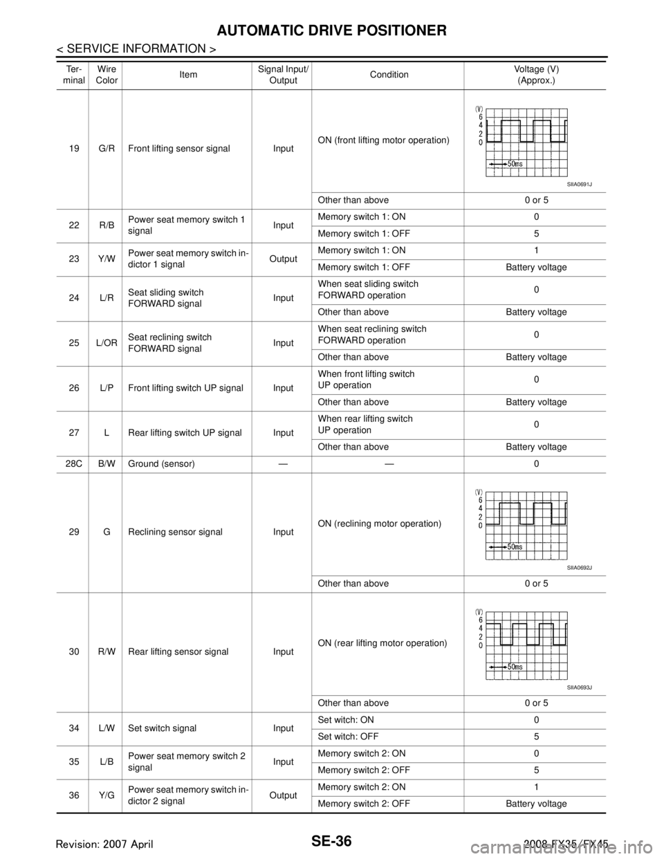
SE-36
< SERVICE INFORMATION >
AUTOMATIC DRIVE POSITIONER
19 G/R Front lifting sensor signal InputON (front lifting motor operation)
Other than above 0 or 5
22 R/B Power seat memory switch 1
signal
InputMemory switch 1: ON 0
Memory switch 1: OFF 5
23 Y/W Power seat memory switch in-
dictor 1 signal
OutputMemory switch 1: ON 1
Memory switch 1: OFF Battery voltage
24 L/R Seat sliding switch
FORWARD signal InputWhen seat sliding switch
FORWARD operation
0
Other than above Battery voltage
25 L/OR Seat reclining switch
FORWARD signal
InputWhen seat reclining switch
FORWARD operation
0
Other than above Battery voltage
26 L/P Front lifting switch UP signal Input When front lifting switch
UP operation
0
Other than above Battery voltage
27 L Rear lifting switch UP signal Input When rear lifting switch
UP operation
0
Other than above Battery voltage
28C B/W Ground (sensor) — — 0
29 G Reclining sensor signal Input ON (reclining motor operation)
Other than above 0 or 5
30 R/W Rear lifting sensor signal Input ON (rear lifting motor operation)
Other than above 0 or 5
34 L/W Set switch signal Input Set witch: ON 0
Set witch: OFF 5
35 L/B Power seat memory switch 2
signal InputMemory switch 2: ON 0
Memory switch 2: OFF 5
36 Y/G Power seat memory switch in-
dictor 2 signal OutputMemory switch 2: ON 1
Memory switch 2: OFF Battery voltage
Te r -
minal Wire
Color ItemSignal Input/
Output Condition Voltage (V)
(Approx.)
SIIA0691J
SIIA0692J
SIIA0693J
3AA93ABC3ACD3AC03ACA3AC03AC63AC53A913A773A893A873A873A8E3A773A983AC73AC93AC03AC3
3A893A873A873A8F3A773A9D3AAF3A8A3A8C3A863A9D3AAF3A8B3A8C
Page 3680 of 3924
AUTOMATIC DRIVE POSITIONERSE-41
< SERVICE INFORMATION >
C
DE
F
G H
J
K L
M A
B
SE
N
O P
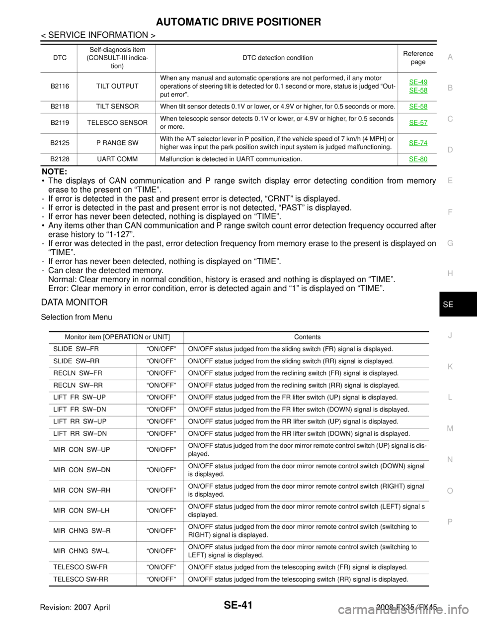
NOTE:
The displays of CAN communication and P range switch display error detecting condition from memory erase to the present on “TIME”.
- If error is detected in the past and present error is detected, “CRNT” is displayed.
- If error is detected in the past and present error is not detected, “PAST” is displayed.
- If error has never been detected, nothing is displayed on “TIME”.
Any items other than CAN communication and P range s witch count error detection frequency occurred after
erase history to “1-127”.
- If error was detected in the past, error detection frequen cy from memory erase to the present is displayed on
“TIME”.
- If error has never been detected, nothing is displayed on “TIME”.
- Can clear the detected memory. Normal: Clear memory in normal condition, hist ory is erased and nothing is displayed on “TIME”.
Error: Clear memory in error condition, error is detected again and “1” is displayed on “TIME”.
DATA MONITOR
Selection from Menu
B2116 TILT OUTPUT When any manual and automatic operations are not performed, if any motor
operations of steering tilt is detected for 0.1 second or more, status is judged “Out-
put error”. SE-49SE-58
B2118 TILT SENSOR When tilt sensor detects 0.1V or lo
wer, or 4.9V or higher, for 0.5 seconds or more.SE-58
B2119 TELESCO SENSORWhen telescopic sensor detects 0.1V or lower, or 4.9V or higher, for 0.5 seconds
or more.
SE-57
B2125 P RANGE SWWith the A/T selector lever in P position, if the vehicle speed of 7 km/h (4 MPH) or
higher was input the park position switch input system is judged malfunctioning. SE-74
B2128 UART COMM Malfunction is detected in UART communication.
SE-80
DTCSelf-diagnosis item
(CONSULT-III indica-
tion) DTC detection condition
Reference
page
Monitor item [OPERATION or UNIT] Contents
SLIDE SW–FR “ON/OFF” ON/OFF status judged from the sliding switch (FR) signal is displayed.
SLIDE SW–RR “ON/OFF” ON/OFF status judged from th e sliding switch (RR) signal is displayed.
RECLN SW–FR “ON/OFF” ON/OFF status judged from the reclining switch (FR) signal is displayed.
RECLN SW–RR “ON/OFF” ON/OFF status judged from the reclining switch (RR) signal is displayed.
LIFT FR SW–UP “ON/OFF” ON/OFF status judged from the FR lifter switch (UP) signal is displayed.
LIFT FR SW–DN “ON/OFF” ON/OFF status judged from the FR lifter switch (DOWN) signal is displayed.
LIFT RR SW–UP “ON/OFF” ON/OFF status judged from the RR lifter switch (UP) signal is displayed.
LIFT RR SW–DN “ON/OFF” ON/OFF status judged from the RR lifter switch (DOWN) signal is displayed.
MIR CON SW–UP “ON/OFF” ON/OFF status judged from the door mirror remote control switch (UP) signal is dis-
played.
MIR CON SW–DN “ON/OFF” ON/OFF status judged from the door mirror remote control switch (DOWN) signal
is displayed.
MIR CON SW–RH “ON/OFF” ON/OFF status judged from the door mirror remote control switch (RIGHT) signal
is displayed.
MIR CON SW–LH “ON/OFF” ON/OFF status judged from the door mirror remote control switch (LEFT) signal s
displayed.
MIR CHNG SW–R “ON/OFF” ON/OFF status judged from the door mirror remote control switch (switching to
RIGHT) signal is displayed.
MIR CHNG SW–L “ON/OFF” ON/OFF status judged from the door mirror remote control switch (switching to
LEFT) signal is displayed.
TELESCO SW-FR “ON/OFF” ON/OFF status judged from the telescoping switch (FR) signal is displayed.
TELESCO SW-RR “ON/OFF” ON/OFF status judged from the telescoping switch (RR) signal is displayed.
3AA93ABC3ACD3AC03ACA3AC03AC63AC53A913A773A893A873A873A8E3A773A983AC73AC93AC03AC3
3A893A873A873A8F3A773A9D3AAF3A8A3A8C3A863A9D3AAF3A8B3A8C