Page 3469 of 3924

PS-14
< SERVICE INFORMATION >
STEERING COLUMN
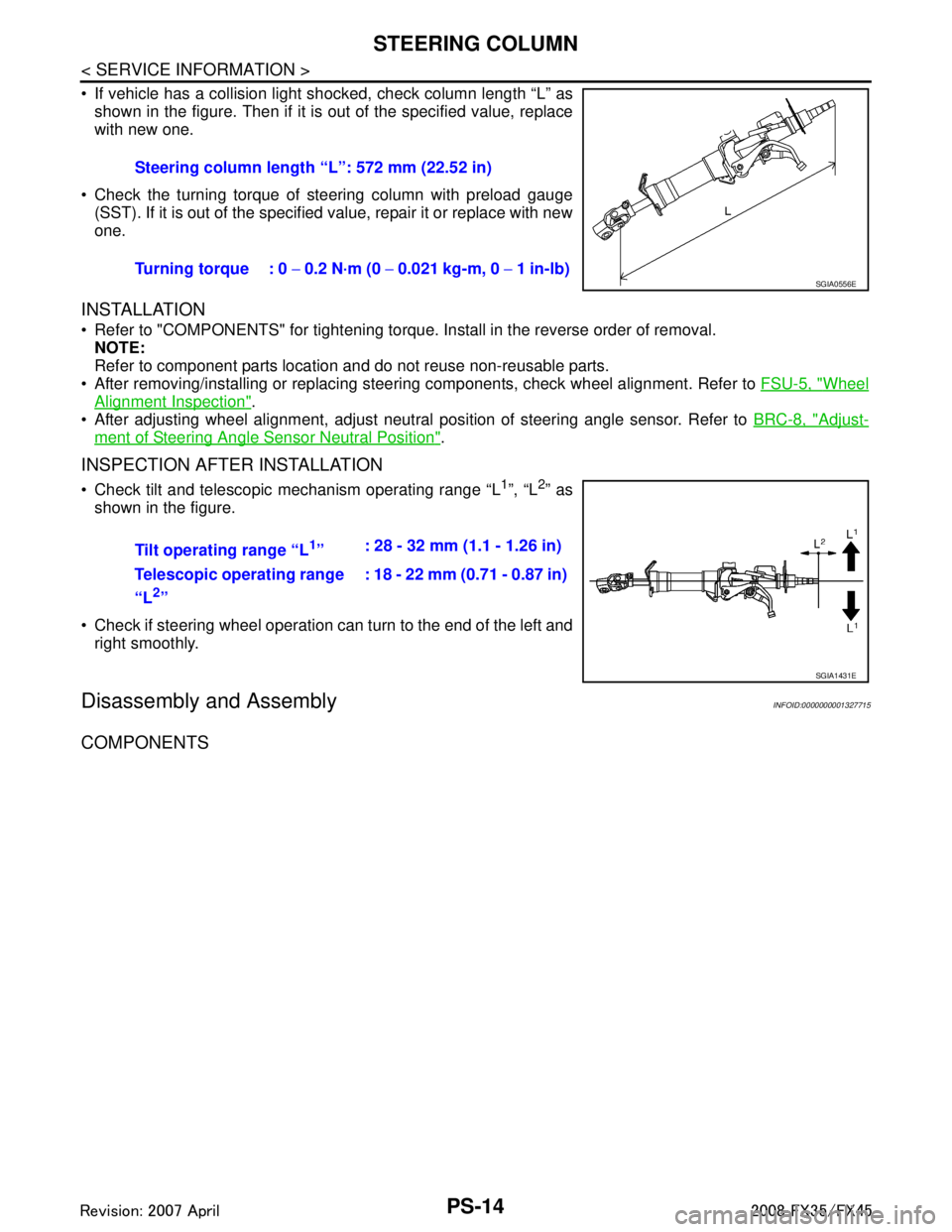
If vehicle has a collision light shocked, check column length “L” as
shown in the figure. Then if it is out of the specified value, replace
with new one.
Check the turning torque of steering column with preload gauge (SST). If it is out of the specified value, repair it or replace with new
one.
INSTALLATION
Refer to "COMPONENTS" for tightening torque. Install in the reverse order of removal.NOTE:
Refer to component parts location and do not reuse non-reusable parts.
After removing/installing or replacing steering components, check wheel alignment. Refer to FSU-5, "
Wheel
Alignment Inspection".
After adjusting wheel alignment, adjust neutral position of steering angle sensor. Refer to BRC-8, "
Adjust-
ment of Steering Angle Sensor Neutral Position".
INSPECTION AFTER INSTALLATION
Check tilt and telescopic mechanism operating range “L1”, “L2” as
shown in the figure.
Check if steering wheel operation can turn to the end of the left and right smoothly.
Disassembly and AssemblyINFOID:0000000001327715
COMPONENTS
Steering column length “L”: 572 mm (22.52 in)
Turning torque : 0 − 0.2 N·m (0 − 0.021 kg-m, 0 − 1 in-lb)
SGIA0556E
Tilt operating range “L1” : 28 - 32 mm (1.1 - 1.26 in)
Telescopic operating range
“L
2” : 18 - 22 mm (0.71 - 0.87 in)
SGIA1431E
3AA93ABC3ACD3AC03ACA3AC03AC63AC53A913A773A893A873A873A8E3A773A983AC73AC93AC03AC3
3A893A873A873A8F3A773A9D3AAF3A8A3A8C3A863A9D3AAF3A8B3A8C
Page 3470 of 3924
STEERING COLUMNPS-15
< SERVICE INFORMATION >
C
DE
F
H I
J
K L
M A
B
PS
N
O P
1. Meter bracket 2. Jacket tube assembly 3. Upper joint
4. Spring 5. Lock nut 6. Lock block
7. Telescopic lock guide 8. Bush spacer 9. Tilt link assembly
10. Cooler 11. Tilt unit assembly 12. Tilt sensor assembly
13. Connector assembly 14. Clamp 15. Spring
16. Telescopic unit assembly 17. Telescopic sensor assembly
SGIA0592E
3AA93ABC3ACD3AC03ACA3AC03AC63AC53A913A773A893A873A873A8E3A773A983AC73AC93AC03AC3
3A893A873A873A8F3A773A9D3AAF3A8A3A8C3A863A9D3AAF3A8B3A8C
Page 3473 of 3924

PS-18
< SERVICE INFORMATION >
POWER STEERING GEAR AND LINKAGE
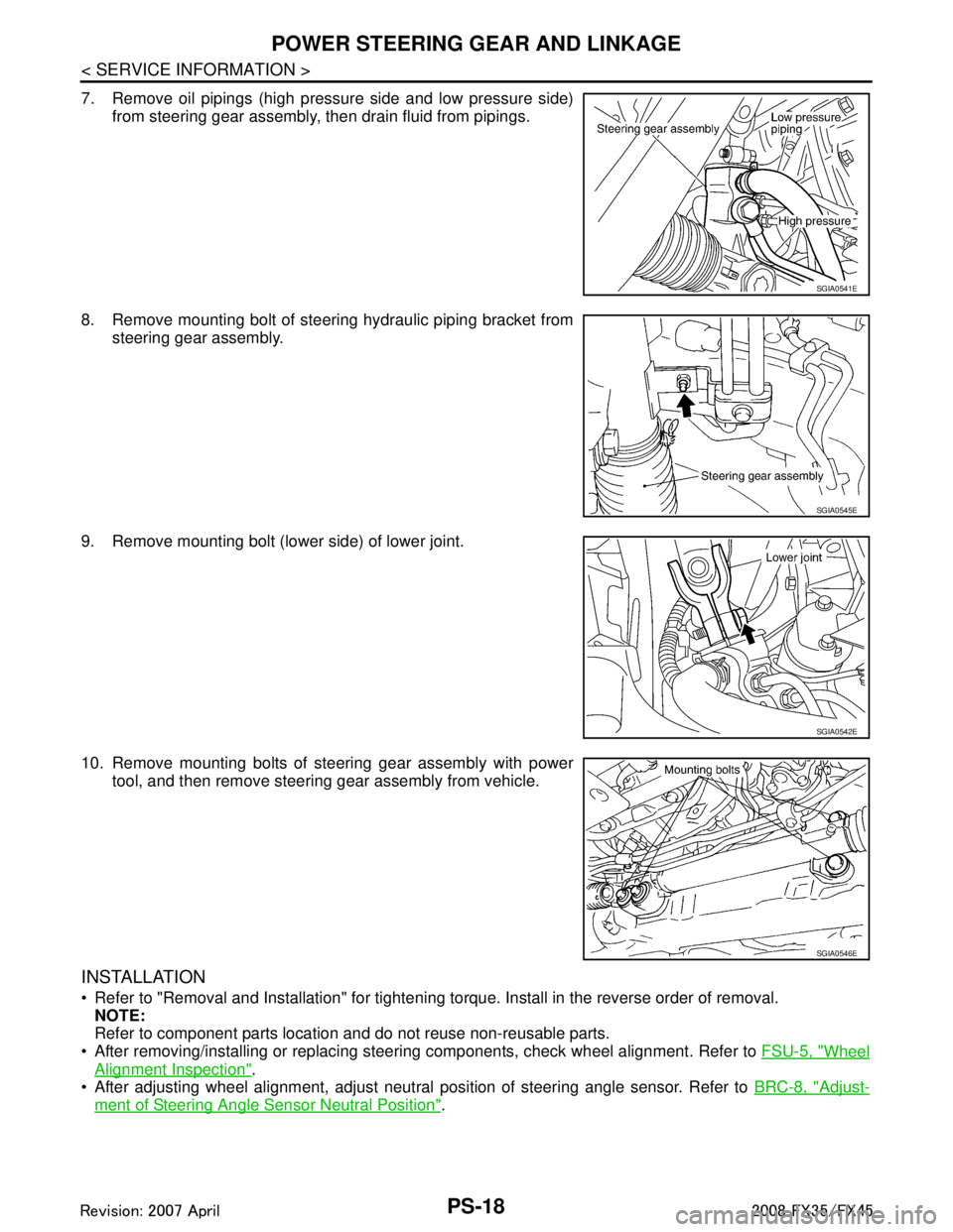
7. Remove oil pipings (high pressure side and low pressure side)from steering gear assembly, then drain fluid from pipings.
8. Remove mounting bolt of steering hydraulic piping bracket from steering gear assembly.
9. Remove mounting bolt (lower side) of lower joint.
10. Remove mounting bolts of steering gear assembly with power tool, and then remove steering gear assembly from vehicle.
INSTALLATION
Refer to "Removal and Installation" for tightening torque. Install in the reverse order of removal.
NOTE:
Refer to component parts location and do not reuse non-reusable parts.
After removing/installing or replacing steering components, check wheel alignment. Refer to FSU-5, "
Wheel
Alignment Inspection".
After adjusting wheel alignment, adjust neutral position of steering angle sensor. Refer to BRC-8, "
Adjust-
ment of Steering Angle Sensor Neutral Position".
SGIA0541E
SGIA0545E
SGIA0542E
SGIA0546E
3AA93ABC3ACD3AC03ACA3AC03AC63AC53A913A773A893A873A873A8E3A773A983AC73AC93AC03AC3
3A893A873A873A8F3A773A9D3AAF3A8A3A8C3A863A9D3AAF3A8B3A8C
Page 3492 of 3924
HYDRAULIC LINEPS-37
< SERVICE INFORMATION >
C
DE
F
H I
J
K L
M A
B
PS
N
O P
HYDRAULIC LINE
ComponentINFOID:0000000001327723
VQ35DE 2WD MODEL
JSGIA0218GB
1. Reservoir tank 2. Reservoir tank bracket 3. Suction hose
4. High pressure hose 5. Power steering oil pump 6. Steering gear assembly
7. Oil cooler 8. Clamp 9. Eye bolt
10. Copper washer 11. Copper washer 12. Eye bolt
13. Eye joint (assembled to high pres- sure side hose) 14. Pressure sensor
Refer to GI-8, "
Component" and the followings for the symbols in the figure.
: Apply power steering fluid.
3AA93ABC3ACD3AC03ACA3AC03AC63AC53A913A773A893A873A873A8E3A773A983AC73AC93AC03AC3
3A893A873A873A8F3A773A9D3AAF3A8A3A8C3A863A9D3AAF3A8B3A8C
Page 3493 of 3924
PS-38
< SERVICE INFORMATION >
HYDRAULIC LINE
VQ35DE AWD MODEL
JSGIA0177GB
1. Reservoir tank 2. Reservoir tank bracket 3. Suction hose
4. High pressure hose 5. Power steering oil pump 6. Steering gear assembly
7. Oil cooler 8. Clamp 9. Eye bolt
10. Copper washer 11. Eye bolt 12. Copper washer
13. Oil pressure sensor
Refer to GI-8, "
Component" and the followings for the symbols in the figure.
: Apply power steering fluid.
3AA93ABC3ACD3AC03ACA3AC03AC63AC53A913A773A893A873A873A8E3A773A983AC73AC93AC03AC3
3A893A873A873A8F3A773A9D3AAF3A8A3A8C3A863A9D3AAF3A8B3A8C
Page 3494 of 3924
HYDRAULIC LINEPS-39
< SERVICE INFORMATION >
C
DE
F
H I
J
K L
M A
B
PS
N
O P
VK45DE AWD MODEL
Removal and InstallationINFOID:0000000001327724
VQ35DE MODELS
Refer to PS-37, "Component" for tightening torque. Install in the reverse order of removal.
NOTE:
Refer to component parts location and do not reuse non-reusable parts.
JSGIA0219GB
1. Reservoir tank 2. Suction hose 3. High pressure hose
4. Oil cooler 5. Pressure sensor 6. Steering gear assembly
7. Clamp 8. Eye bolt 9. Copper washer
10. Reservoir tank bracket 11. Eye bolt
Refer to GI-8, "
Component" and the followings for the symbols in the figure.
: Apply power steering fluid.
3AA93ABC3ACD3AC03ACA3AC03AC63AC53A913A773A893A873A873A8E3A773A983AC73AC93AC03AC3
3A893A873A873A8F3A773A9D3AAF3A8A3A8C3A863A9D3AAF3A8B3A8C
Page 3495 of 3924

PS-40
< SERVICE INFORMATION >
HYDRAULIC LINE
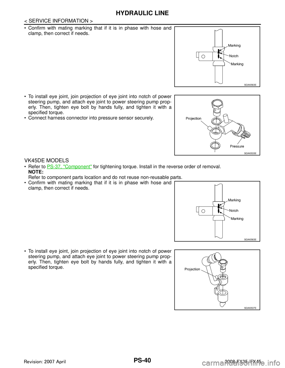
Confirm with mating marking that if it is in phase with hose andclamp, then correct if needs.
To install eye joint, join projection of eye joint into notch of power steering pump, and attach eye joint to power steering pump prop-
erly. Then, tighten eye bolt by hands fully, and tighten it with a
specified torque.
Connect harness connector into pressure sensor securely.
VK45DE MODELS
Refer to PS-37, "Component" for tightening torque. Install in the reverse order of removal.
NOTE:
Refer to component parts location and do not reuse non-reusable parts.
Confirm with mating marking that if it is in phase with hose and clamp, then correct if needs.
To install eye joint, join projection of eye joint into notch of power steering pump, and attach eye joint to power steering pump prop-
erly. Then, tighten eye bolt by hands fully, and tighten it with a
specified torque.
SGIA0563E
SGIA0533E
SGIA0563E
SGIA0537E
3AA93ABC3ACD3AC03ACA3AC03AC63AC53A913A773A893A873A873A8E3A773A983AC73AC93AC03AC3
3A893A873A873A8F3A773A9D3AAF3A8A3A8C3A863A9D3AAF3A8B3A8C
Page 3504 of 3924

RAX-6
< SERVICE INFORMATION >
REAR WHEEL HUB AND KNUCKLE
REAR WHEEL HUB AND KNUCKLE
On-Vehicle InspectionINFOID:0000000001327526
Make sure the mounting conditions (looseness, back lash) of each component and component status (wear,
damage) are normal.
WHEEL BEARING INSPECTION
With the vehicle raised, inspect the following.
Move wheel hub in the axial direction by hand. Che ck that there is no looseness of front wheel bearing.
Rotate wheel hub and make sure there is no unusual noi se or other irregular conditions. If there are any
irregular conditions, replace wheel hub and bearing assembly.
Removal and InstallationINFOID:0000000001327527
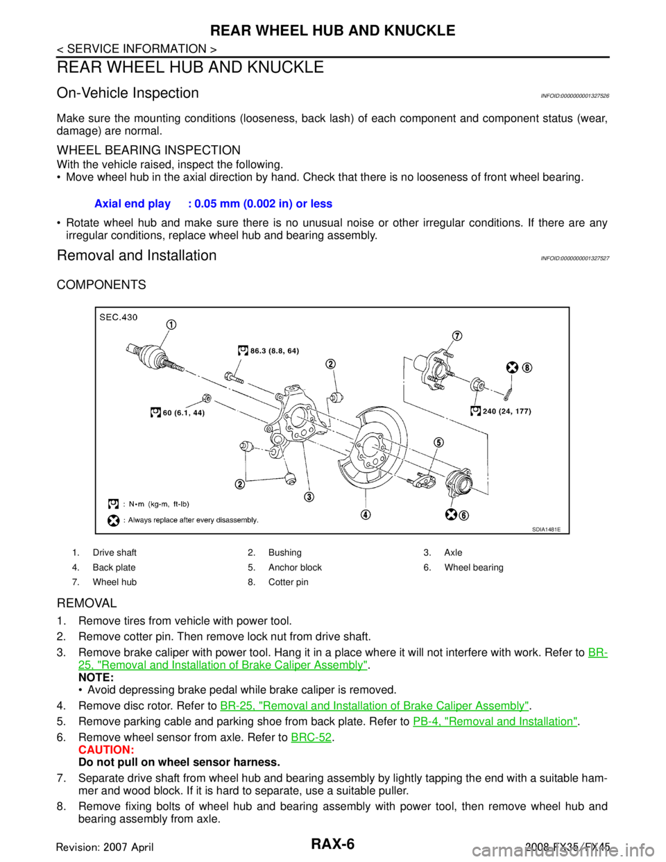
COMPONENTS
REMOVAL
1. Remove tires from vehicle with power tool.
2. Remove cotter pin. Then remove lock nut from drive shaft.
3. Remove brake caliper with power tool. Hang it in a place where it will not interfere with work. Refer to BR-
25, "Removal and Installation of Brake Caliper Assembly".
NOTE:
Avoid depressing brake pedal while brake caliper is removed.
4. Remove disc rotor. Refer to BR-25, "
Removal and Installation of Brake Caliper Assembly".
5. Remove parking cable and parking shoe from back plate. Refer to PB-4, "
Removal and Installation".
6. Remove wheel sensor from axle. Refer to BRC-52
.
CAUTION:
Do not pull on wheel sensor harness.
7. Separate drive shaft from wheel hub and bearing assembly by lightly tapping the end with a suitable ham- mer and wood block. If it is hard to separate, use a suitable puller.
8. Remove fixing bolts of wheel hub and bearing assembly with power tool, then remove wheel hub and bearing assembly from axle.Axial end play : 0.05 mm (0.002 in) or less
1. Drive shaft 2. Bushing 3. Axle
4. Back plate 5. Anchor block 6. Wheel bearing
7. Wheel hub 8. Cotter pin
SDIA1481E
3AA93ABC3ACD3AC03ACA3AC03AC63AC53A913A773A893A873A873A8E3A773A983AC73AC93AC03AC3
3A893A873A873A8F3A773A9D3AAF3A8A3A8C3A863A9D3AAF3A8B3A8C