2008 INFINITI FX35 section pg
[x] Cancel search: section pgPage 3021 of 3924
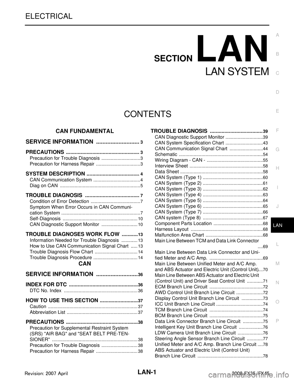
LAN-1
ELECTRICAL
C
DE
F
G H
I
J
L
M
SECTION LAN
A
B
LAN
N
O P
CONTENTS
LAN SYSTEM
CAN FUNDAMENTAL
SERVICE INFORMATION .. ..........................
3
PRECAUTIONS .............................................. .....3
Precaution for Trouble Diagnosis ........................ ......3
Precaution for Harness Repair ..................................3
SYSTEM DESCRIPTION .....................................4
CAN Communication System .............................. ......4
Diag on CAN .............................................................5
TROUBLE DIAGNOSIS ......................................7
Condition of Error Detection ................................ ......7
Symptom When Error Occurs in CAN Communi-
cation System ...................................................... ......
7
Self-Diagnosis .........................................................10
CAN Diagnostic Support Monitor ............................10
TROUBLE DIAGNOSES WORK FLOW ............13
Information Needed for Trouble Diagnosis ......... ....13
How to Use CAN Communication Signal Chart ......13
Trouble Diagnosis Flow Chart .................................14
Trouble Diagnosis Procedure ..................................14
CAN
SERVICE INFORMATION .. .........................
36
INDEX FOR DTC ............................................ ....36
DTC No. Index .................................................... ....36
HOW TO USE THIS SECTION ...........................37
Caution ................................................................ ....37
Abbreviation List ......................................................37
PRECAUTIONS ..................................................38
Precaution for Supplemental Restraint System
(SRS) "AIR BAG" and "SEAT BELT PRE-TEN-
SIONER" ............................................................. ....
38
Precaution for Trouble Diagnosis ............................38
Precaution for Harness Repair ................................38
TROUBLE DIAGNOSIS ....................................39
CAN Diagnostic Support Monitor ......................... ....39
CAN System Specification Chart .............................43
CAN Communication Signal Chart ..........................44
Schematic ................................................................54
Wiring Diagram - CAN - ...........................................55
Interview Sheet ........................................................58
Data Sheet ...............................................................58
CAN System (Type 1) ..............................................60
CAN System (Type 2) ..............................................61
CAN System (Type 3) ..............................................62
CAN System (Type 4) ..............................................63
CAN System (Type 5) ..............................................64
CAN System (Type 6) ..............................................65
CAN System (Type 7) ..............................................66
CAN system (Type 8) ..............................................67
Component Parts Location ......................................68
Harness Layout .......................................................68
Malfunction Area Chart ............................................68
Main Line Between TCM and Data Link Connector
....
69
Main Line Between Data Link Connector and Uni-
fied Meter and A/C Amp. .........................................
69
Main Line Between Unified Meter and A/C Amp.
and ABS Actuator and Electric Unit (Control Unit) ....
70
Main Line Between ABS Actu ator and Electric Unit
(Control Unit) and Driver Seat Control Unit .............
71
ECM Branch Line Circuit ..................................... ....72
AWD Control Unit Branch Line Circuit .....................72
Display Control Unit Branch Line Circuit .................73
ICC Unit Branch Line Circuit ................................ ....74
TCM Branch Line Circuit .........................................74
BCM Branch Line Circuit .........................................75
Data Link Connector Branch Line Circuit ................75
Intelligent Key Unit Branch Line Circuit ...................76
LDW Camera Unit Branch Line Circuit ....................76
Steering Angle Sensor Branch Line Circuit .............77
Unified Meter and A/C Amp. Branch Line Circuit ....78
ABS Actuator and Electric Unit (Control Unit)
Branch Line Circuit ..................................................
78
3AA93ABC3ACD3AC03ACA3AC03AC63AC53A913A773A893A873A873A8E3A773A983AC73AC93AC03AC3
3A893A873A873A8F3A773A9D3AAF3A8A3A8C3A863A9D3AAF3A8B3A8C
Page 3035 of 3924
![INFINITI FX35 2008 Service Manual
TROUBLE DIAGNOSES WORK FLOWLAN-15
< SERVICE INFORMATION > [CAN FUNDAMENTAL]
C
D
E
F
G H
I
J
L
M A
B
LAN
N
O P
Result: Symptom
NOTE:
Check normal units as well as error symptoms.
- Example: Circui INFINITI FX35 2008 Service Manual
TROUBLE DIAGNOSES WORK FLOWLAN-15
< SERVICE INFORMATION > [CAN FUNDAMENTAL]
C
D
E
F
G H
I
J
L
M A
B
LAN
N
O P
Result: Symptom
NOTE:
Check normal units as well as error symptoms.
- Example: Circui](/manual-img/42/57017/w960_57017-3034.png)
TROUBLE DIAGNOSES WORK FLOWLAN-15
< SERVICE INFORMATION > [CAN FUNDAMENTAL]
C
D
E
F
G H
I
J
L
M A
B
LAN
N
O P
Result: Symptom
NOTE:
Check normal units as well as error symptoms.
- Example: Circuit between ECM and the combination meter is judged normal if the customer indicates tachometer functions normally.
When a CAN communication system error is present, mult iple control units may malfunction or go into fail-
safe mode.
Indication of the combination meter is important to det ect the root cause because it is the most obvious to
the customer, and it performs CA N communication with many units.
INSPECTION OF VEHICLE CONDITION
Check whether or not “U1000” or “U1001” is indi cated on “SELF-DIAG RESULTS” by CONSULT-III.
NOTE:
Root cause cannot be detected using the procedure in this section if “U1000” or “U1001” is not indicated.
Check whether the symptom is reproduced or not.
NOTE:
Do not turn the ignition switch OFF or disconnect the battery cable while reproducing the error. The error may temporarily correct itself, making it difficult to determine the root cause.
The procedures for present errors differ from the procedures for past errors. Refer to "DETECT THE
ROOT CAUSE".
CHECK OF CAN SYSTEM TYPE (HOW TO US E CAN SYSTEM TYPE SPECIFICATION CHART)
Determine CAN system type based on vehicle equipm ent. Then choose the correct diagnosis sheet.
NOTE:
There are two styles for CAN system type specificat ion charts. Depending on the number of available system
types, either style A or style B may be used.
CAN System Type Specification Chart (Style A)
NOTE:
SKIB8717E
3AA93ABC3ACD3AC03ACA3AC03AC63AC53A913A773A893A873A873A8E3A773A983AC73AC93AC03AC3
3A893A873A873A8F3A773A9D3AAF3A8A3A8C3A863A9D3AAF3A8B3A8C
Page 3057 of 3924
![INFINITI FX35 2008 Service Manual
HOW TO USE THIS SECTIONLAN-37
< SERVICE INFORMATION > [CAN]
C
D
E
F
G H
I
J
L
M A
B
LAN
N
O P
HOW TO USE THIS SECTION
CautionINFOID:0000000001328628
This section describes information peculiar to a INFINITI FX35 2008 Service Manual
HOW TO USE THIS SECTIONLAN-37
< SERVICE INFORMATION > [CAN]
C
D
E
F
G H
I
J
L
M A
B
LAN
N
O P
HOW TO USE THIS SECTION
CautionINFOID:0000000001328628
This section describes information peculiar to a](/manual-img/42/57017/w960_57017-3056.png)
HOW TO USE THIS SECTIONLAN-37
< SERVICE INFORMATION > [CAN]
C
D
E
F
G H
I
J
L
M A
B
LAN
N
O P
HOW TO USE THIS SECTION
CautionINFOID:0000000001328628
This section describes information peculiar to a v ehicle, sheets for trouble diagnosis, and inspection proce-
dures.
For trouble diagnosis procedure LAN-14, "
Trouble Diagnosis Procedure".
Abbreviation ListINFOID:0000000001328629
Abbreviations in CAN communication signal chart, and the diagnosis sheet are as per the following list.
Abbreviation Unit name SELECT SYSTEM
(CONSULT-III) CAN DIAG SUPPORT MNTR
(CONSULT-III)
4WD AWD control unit ALL MODE AWD/4WD AWD/4WD
A-BAG Air bag diagnosis sensor unit AIR BAG – ABS ABS actuator and electric un it (control unit) ABS VDC/TCS/ABS
ADP Driver seat control unit AUTO DRIVE POS. –
BCM BCM BCM BCM/SEC
DISP Display control unit – DISPLAY DLC Data link connector – –
ECM ECM ENGINE ECM
ICC ICC unit ICC ICC
ICC/e4WD
I-KEY Intelligent Key unit INTELLIGENT KEY I-KEY
IPDM-E IPDM E/R IPDM E/R IPDM E/R LANE LDW camera unit LDW –
LASER ICC sensor – ICC SENSOR M&A Unified meter and A/C amp. METER/M&A METER/M&A
STRG Steering angle sensor – STRG TCM TCM TRANSMISSION TCM
3AA93ABC3ACD3AC03ACA3AC03AC63AC53A913A773A893A873A873A8E3A773A983AC73AC93AC03AC3
3A893A873A873A8F3A773A9D3AAF3A8A3A8C3A863A9D3AAF3A8B3A8C
Page 3103 of 3924
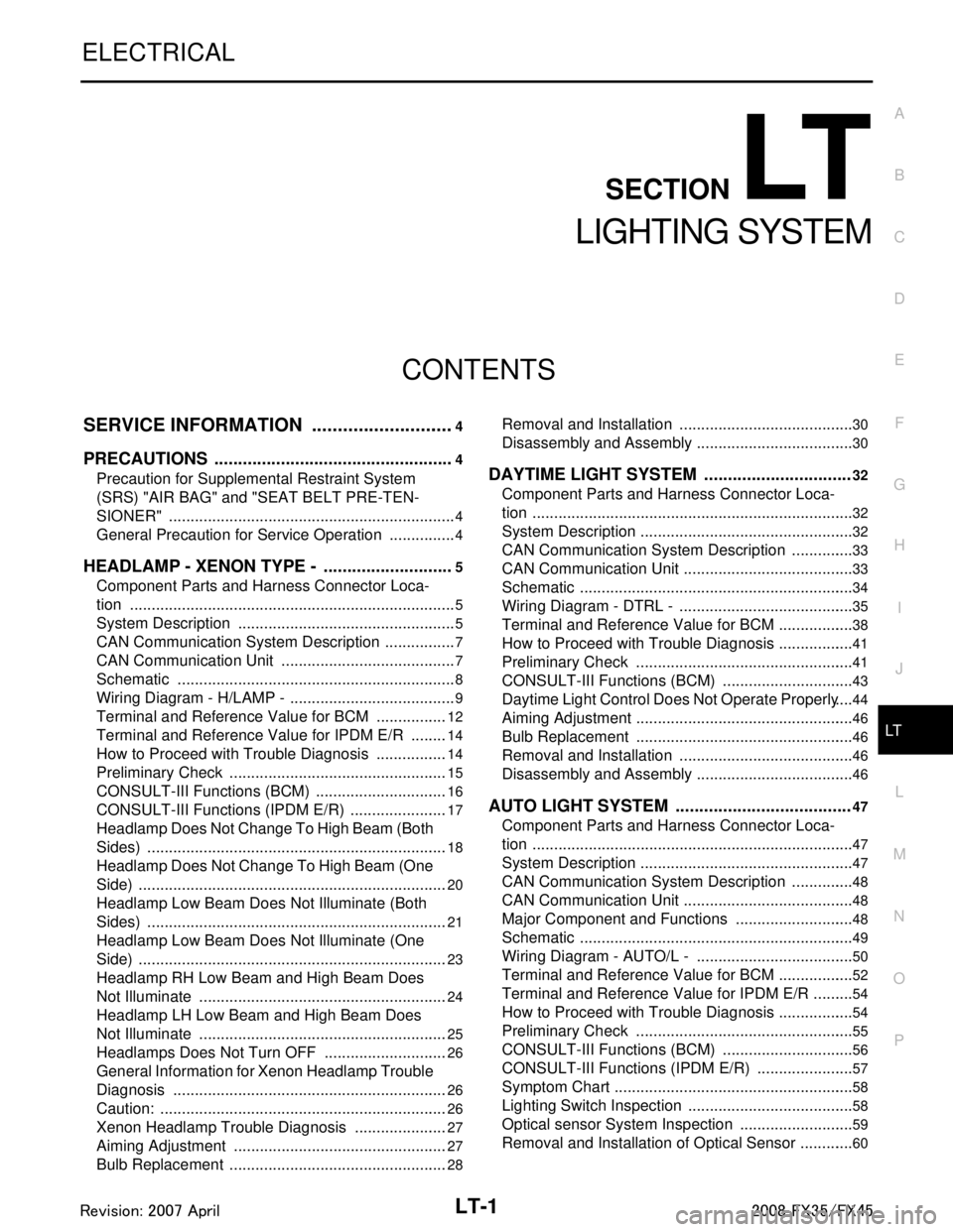
LT-1
ELECTRICAL
C
DE
F
G H
I
J
L
M
SECTION LT
A
B
LT
N
O P
CONTENTS
LIGHTING SYSTEM
SERVICE INFORMATION .. ..........................4
PRECAUTIONS .............................................. .....4
Precaution for Supplemental Restraint System
(SRS) "AIR BAG" and "SEAT BELT PRE-TEN-
SIONER" ............................................................. ......
4
General Precaution for Service Operation ................4
HEADLAMP - XENON TYPE - ............................5
Component Parts and Harness Connector Loca-
tion ...................................................................... ......
5
System Description ...................................................5
CAN Communication System Description .................7
CAN Communication Unit .........................................7
Schematic .................................................................8
Wiring Diagram - H/LAMP - .......................................9
Terminal and Reference Value for BCM .................12
Terminal and Reference Value for IPDM E/R .........14
How to Proceed with Trouble Diagnosis .................14
Preliminary Check ...................................................15
CONSULT-III Functions (BCM) ...............................16
CONSULT-III Functions (IPDM E/R) .......................17
Headlamp Does Not Change To High Beam (Both
Sides) ......................................................................
18
Headlamp Does Not Change To High Beam (One
Side) ........................................................................
20
Headlamp Low Beam Does Not Illuminate (Both
Sides) .................................................................. ....
21
Headlamp Low Beam Does Not Illuminate (One
Side) .................................................................... ....
23
Headlamp RH Low Beam and High Beam Does
Not Illuminate ..........................................................
24
Headlamp LH Low Beam and High Beam Does
Not Illuminate ..........................................................
25
Headlamps Does Not Turn OFF .............................26
General Information for Xenon Headlamp Trouble
Diagnosis ................................................................
26
Caution: ...................................................................26
Xenon Headlamp Trouble Diagnosis ......................27
Aiming Adjustment ..................................................27
Bulb Replacement ...................................................28
Removal and Installation ..................................... ....30
Disassembly and Assembly .....................................30
DAYTIME LIGHT SYSTEM ...............................32
Component Parts and Harness Connector Loca-
tion ....................................................................... ....
32
System Description ..................................................32
CAN Communication System Description ...............33
CAN Communication Unit ........................................33
Schematic ................................................................34
Wiring Diagram - DTRL - .........................................35
Terminal and Reference Value for BCM ..................38
How to Proceed with Trouble Diagnosis ..................41
Preliminary Check ...................................................41
CONSULT-III Functions (BCM) ...............................43
Daytime Light Control Does Not Operate Properly ....44
Aiming Adjustment ...................................................46
Bulb Replacement ...................................................46
Removal and Installation .........................................46
Disassembly and Assembly .....................................46
AUTO LIGHT SYSTEM .....................................47
Component Parts and Harness Connector Loca-
tion ...........................................................................
47
System Description ..................................................47
CAN Communication System Description ...............48
CAN Communication Unit ........................................48
Major Component and Functions ............................48
Schematic ................................................................49
Wiring Diagram - AUTO/L - .....................................50
Terminal and Reference Value for BCM ..................52
Terminal and Reference Value for IPDM E/R ..........54
How to Proceed with Trouble Diagnosis ..................54
Preliminary Check ...................................................55
CONSULT-III Functions (BCM) ...............................56
CONSULT-III Functions (IPDM E/R) .......................57
Symptom Chart ........................................................58
Lighting Switch Inspection .......................................58
Optical sensor System Inspection ...........................59
Removal and Installation of Optical Sensor .............60
3AA93ABC3ACD3AC03ACA3AC03AC63AC53A913A773A893A873A873A8E3A773A983AC73AC93AC03AC3
3A893A873A873A8F3A773A9D3AAF3A8A3A8C3A863A9D3AAF3A8B3A8C
Page 3286 of 3924
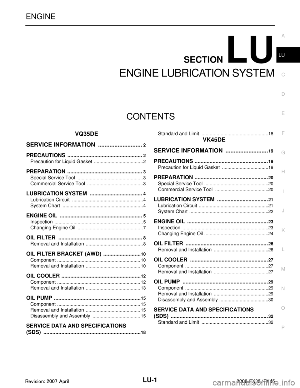
LU-1
ENGINE
C
DE
F
G H
I
J
K L
M
SECTION LU
A
LU
N
O P
CONTENTS
ENGINE LUBRICATION SYSTEM
VQ35DE
SERVICE INFORMATION .. ..........................
2
PRECAUTIONS .............................................. .....2
Precaution for Liquid Gasket ............................... ......2
PREPARATION ...................................................3
Special Service Tool ........................................... ......3
Commercial Service Tool ..........................................3
LUBRICATION SYSTEM ....................................4
Lubrication Circuit ............................................... ......4
System Chart ............................................................4
ENGINE OIL ........................................................5
Inspection ............................................................ ......5
Changing Engine Oil .................................................7
OIL FILTER .........................................................8
Removal and Installation ..................................... ......8
OIL FILTER BRACKET (AWD) ..........................10
Component .......................................................... ....10
Removal and Installation .........................................10
OIL COOLER ......................................................12
Component .......................................................... ....12
Removal and Installation .........................................13
OIL PUMP ...........................................................15
Component .......................................................... ....15
Removal and Installation .........................................15
Disassembly and Assembly ....................................15
SERVICE DATA AND SPECIFICATIONS
(SDS) ..................................................................
18
Standard and Limit .............................................. ....18
VK45DE
SERVICE INFORMATION .. .........................
19
PRECAUTIONS .................................................19
Precaution for Liquid Gasket ............................... ....19
PREPARATION .................................................20
Special Service Tool ................................................20
Commercial Service Tool ........................................20
LUBRICATION SYSTEM ..................................21
Lubrication Circuit ....................................................21
System Chart ...........................................................22
ENGINE OIL ......................................................23
Inspection ................................................................23
Changing Engine Oil ................................................24
OIL FILTER .......................................................26
Removal and Installation .........................................26
OIL COOLER ....................................................27
Component ..............................................................27
Removal and Installation .........................................27
OIL PUMP .........................................................29
Component ..............................................................29
Removal and Installation .........................................29
Disassembly and Assembly .....................................30
SERVICE DATA AND SPECIFICATIONS
(SDS) .................................................................
32
Standard and Limit ..................................................32
3AA93ABC3ACD3AC03ACA3AC03AC63AC53A913A773A893A873A873A8E3A773A983AC73AC93AC03AC3
3A893A873A873A8F3A773A9D3AAF3A8A3A8C3A863A9D3AAF3A8B3A8C
Page 3318 of 3924
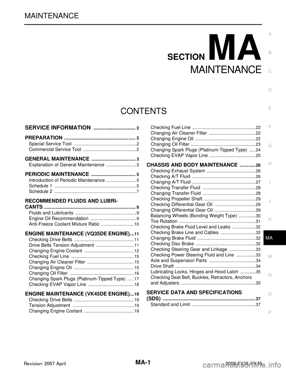
MA-1
MAINTENANCE
C
DE
F
G H
I
J
K
M
SECTION MA
A
B
MA
N
O P
CONTENTS
MAINTENANCE
SERVICE INFORMATION .. ..........................2
PREPARATION .............................................. .....2
Special Service Tool ........................................... ......2
Commercial Service Tool ..........................................2
GENERAL MAINTENANCE ................................3
Explanation of General Maintenance .................. ......3
PERIODIC MAINTENANCE ................................5
Introduction of Periodic Maintenance .................. ......5
Schedule 1 ................................................................5
Schedule 2 ................................................................7
RECOMMENDED FLUIDS AND LUBRI-
CANTS .................................................................
9
Fluids and Lubricants .......................................... ......9
Engine Oil Recommendation ....................................9
Anti-Freeze Coolant Mixture Ratio ..........................10
ENGINE MAINTENANCE (VQ35DE ENGINE) ....11
Checking Drive Belts ........................................... ....11
Drive Belts Tension Adjustment ..............................11
Changing Engine Coolant .......................................12
Checking Fuel Line .................................................15
Changing Air Cleaner Filter .....................................15
Changing Engine Oil ...............................................15
Changing Oil Filter ..................................................16
Changing Spark Plugs (Platinum-Tipped Type) ......17
Checking EVAP Vapor Line ....................................18
ENGINE MAINTENANCE (VK45DE ENGINE) ....19
Checking Drive Belts ........................................... ....19
Tension Adjustment ................................................19
Changing Engine Coolant .......................................19
Checking Fuel Line .............................................. ....22
Changing Air Cleaner Filter .....................................22
Changing Engine Oil ................................................22
Changing Oil Filter ...................................................23
Changing Spark Plugs (Platinum-Tipped Type) ......24
Checking EVAP Vapor Line .....................................25
CHASSIS AND BODY MAINTENANCE ...........26
Checking Exhaust System ................................... ....26
Checking A/T Fluid ..................................................26
Changing A/T Fluid ..................................................27
Checking Transfer Fluid ..........................................28
Changing Transfer Fluid ..........................................28
Checking Propeller Shaft .........................................29
Checking Differential Gear Oil .................................29
Changing Differential Gear Oil .................................29
Balancing Wheels (Bonding Weight Type) ..............30
Tire Rotation ............................................................31
Checking Brake Fluid Level and Leaks ...................32
Checking Brake Line and Cables ............................32
Changing Brake Fluid ..............................................32
Checking Disc Brake ...............................................32
Checking Steering Gear and Linkage ......................33
Checking Power Steering Fluid and Line ................33
Axle and Suspension Parts .....................................34
Drive Shaft ...............................................................34
Lubricating Locks, Hinges and Hood Latch .............35
Checking Seat Belt, Buckles, Retractors, Anchors
and Adjusters ...........................................................
35
SERVICE DATA AND SPECIFICATIONS
(SDS) .................................................................
37
Standard and Limit ..................................................37
3AA93ABC3ACD3AC03ACA3AC03AC63AC53A913A773A893A873A873A8E3A773A983AC73AC93AC03AC3
3A893A873A873A8F3A773A9D3AAF3A8A3A8C3A863A9D3AAF3A8B3A8C
Page 3322 of 3924
PERIODIC MAINTENANCEMA-5
< SERVICE INFORMATION >
C
DE
F
G H
I
J
K
M A
B
MA
N
O P
PERIODIC MAINTENANCE
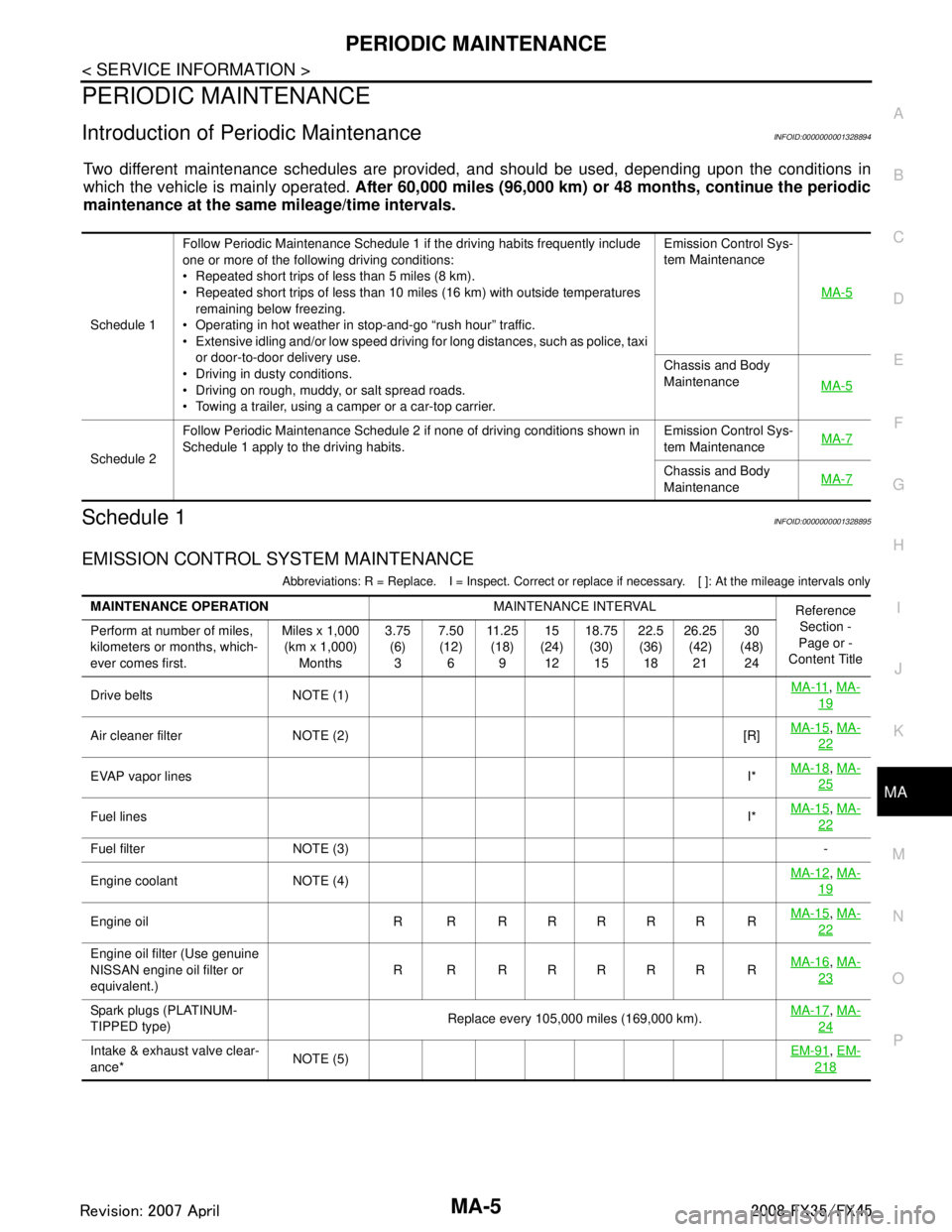
Introduction of Periodic MaintenanceINFOID:0000000001328894
Two different maintenance schedules are provi ded, and should be used, depending upon the conditions in
which the vehicle is mainly operated. After 60,000 miles (96,000 km) or 48 months, continue the periodic
maintenance at the same mileage/time intervals.
Schedule 1INFOID:0000000001328895
EMISSION CONTROL SYSTEM MAINTENANCE
Abbreviations: R = Replace. I = Inspect. Correct or r eplace if necessary. [ ]: At the mileage intervals only
Schedule 1Follow Periodic Maintenance Schedule 1 if the driving habits frequently include
one or more of the following driving conditions:
Repeated short trips of less than 5 miles (8 km).
Repeated short trips of less than 10 miles (16 km) with outside temperatures
remaining below freezing.
Operating in hot weather in stop-and-go “rush hour” traffic.
Extensive idling and/or low speed driving for long distances, such as police, taxi or door-to-door delivery use.
Driving in dusty conditions.
Driving on rough, muddy, or salt spread roads.
Towing a trailer, using a camper or a car-top carrier. Emission Control Sys-
tem Maintenance
MA-5
Chassis and Body
MaintenanceMA-5
Schedule 2Follow Periodic Maintenance Schedule 2 if none of driving conditions shown in
Schedule 1 apply to the driving habits.
Emission Control Sys-
tem Maintenance
MA-7Chassis and Body
Maintenance
MA-7
MAINTENANCE OPERATION
MAINTENANCE INTERVAL
Reference
Section -
Page or -
Content Title
Perform at number of miles,
kilometers or months, which-
ever comes first. Miles x 1,000
(km x 1,000) Months 3.75
(6)3 7.50
(12) 6 11 . 2 5
(18) 9 15
(24) 12 18.75
(30)15 22.5
(36) 18 26.25
(42)21 30
(48) 24
Drive belts NOTE (1) MA-11
,
MA-
19
Air cleaner filter NOTE (2) [R] MA-15,
MA-
22
EVAP vapor lines I*MA-18,
MA-
25
Fuel lines I*MA-15,
MA-
22
Fuel filter NOTE (3) -
Engine coolant NOTE (4) MA-12
,
MA-
19
Engine oil R R R R R R R R MA-15,
MA-
22
Engine oil filter (Use genuine
NISSAN engine oil filter or
equivalent.) R R RRRRR R
MA-16,
MA-
23
Spark plugs (PLATINUM-
TIPPED type) Replace every 105,000 miles (169,000 km).
MA-17,
MA-
24
Intake & exhaust valve clear-
ance* NOTE (5) EM-91,
EM-
218
3AA93ABC3ACD3AC03ACA3AC03AC63AC53A913A773A893A873A873A8E3A773A983AC73AC93AC03AC3
3A893A873A873A8F3A773A9D3AAF3A8A3A8C3A863A9D3AAF3A8B3A8C
Page 3323 of 3924
MA-6
< SERVICE INFORMATION >
PERIODIC MAINTENANCE
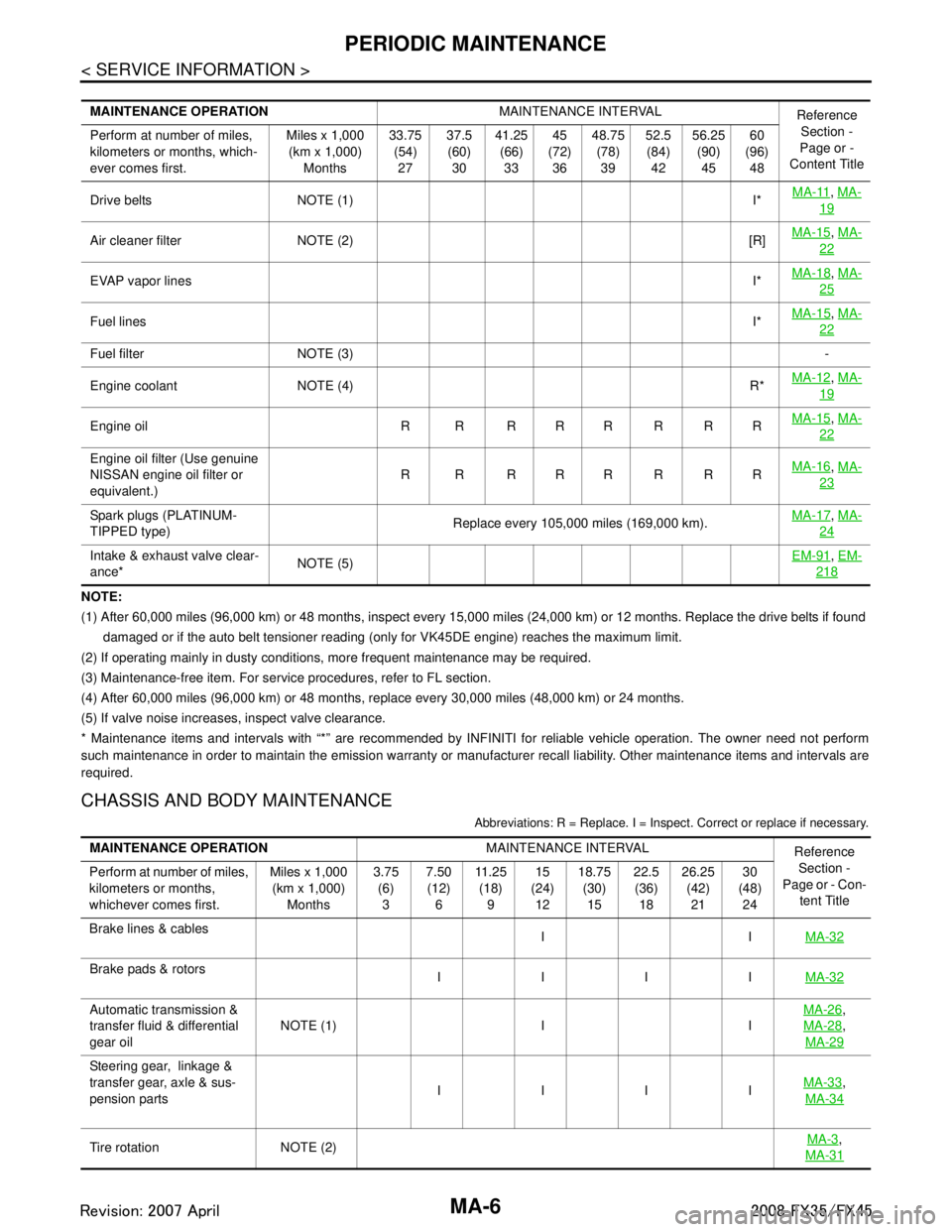
NOTE:
(1) After 60,000 miles (96,000 km) or 48 months, inspect every 15,000 miles (24,000 km) or 12 months. Replace the drive belts if found
damaged or if the auto belt tensioner reading (only for VK45DE engine) reaches the maximum limit.
(2) If operating mainly in dusty conditions, more frequent maintenance may be required.
(3) Maintenance-free item. For service procedures, refer to FL section.
(4) After 60,000 miles (96,000 km) or 48 months, replace every 30,000 miles (48,000 km) or 24 months.
(5) If valve noise increases, inspect valve clearance.
* Maintenance items and intervals with “*” are recommended by INFINITI for reliable vehicle operation. The owner need not perfo rm
such maintenance in order to maintain the emission warranty or manufacturer recall liability. Other maintenance items and inter vals are
required.
CHASSIS AND BODY MAINTENANCE
Abbreviations: R = Replace. I = Inspec t. Correct or replace if necessary.
MAINTENANCE OPERATION MAINTENANCE INTERVAL
Reference
Section -
Page or -
Content Title
Perform at number of miles,
kilometers or months, which-
ever comes first. Miles x 1,000
(km x 1,000) Months 33.75
(54)27 37.5
(60) 30 41.25
(66)33 45
(72) 36 48.75
(78)39 52.5
(84) 42 56.25
(90)45 60
(96) 48
Drive belts NOTE (1) I* MA-11
,
MA-
19
Air cleaner filter NOTE (2) [R] MA-15,
MA-
22
EVAP vapor lines I*MA-18,
MA-
25
Fuel lines I*MA-15,
MA-
22
Fuel filter NOTE (3) -
Engine coolant NOTE (4) R* MA-12
,
MA-
19
Engine oil R R R R R R R R MA-15,
MA-
22
Engine oil filter (Use genuine
NISSAN engine oil filter or
equivalent.) R R RRRRRR
MA-16,
MA-
23
Spark plugs (PLATINUM-
TIPPED type) Replace every 105,000 miles (169,000 km).MA-17,
MA-
24
Intake & exhaust valve clear-
ance* NOTE (5) EM-91,
EM-
218
MAINTENANCE OPERATION MAINTENANCE INTERVAL
Reference
Section -
Page or - Con-
tent Title
Perform at number of miles,
kilometers or months,
whichever comes first. Miles x 1,000
(km x 1,000) Months 3.75
(6)3 7.50
(12) 6 11 . 2 5
(18) 9 15
(24) 12 18.75
(30)15 22.5
(36) 18 26.25
(42)21 30
(48) 24
Brake lines & cables IIMA-32
Brake pads & rotors
IIII MA-32
Automatic transmission &
transfer fluid & differential
gear oilNOTE (1) I I MA-26,
MA-28
,
MA-29
Steering gear, linkage &
transfer gear, axle & sus-
pension parts IIII
MA-33
,
MA-34
Tire rotation NOTE (2) MA-3,
MA-31
3AA93ABC3ACD3AC03ACA3AC03AC63AC53A913A773A893A873A873A8E3A773A983AC73AC93AC03AC3
3A893A873A873A8F3A773A9D3AAF3A8A3A8C3A863A9D3AAF3A8B3A8C