2008 INFINITI FX35 section pg
[x] Cancel search: section pgPage 3443 of 3924
PR-1
DRIVELINE/AXLE
CEF
G H
I
J
K L
M
SECTION PR
A
B
PR
N
O P
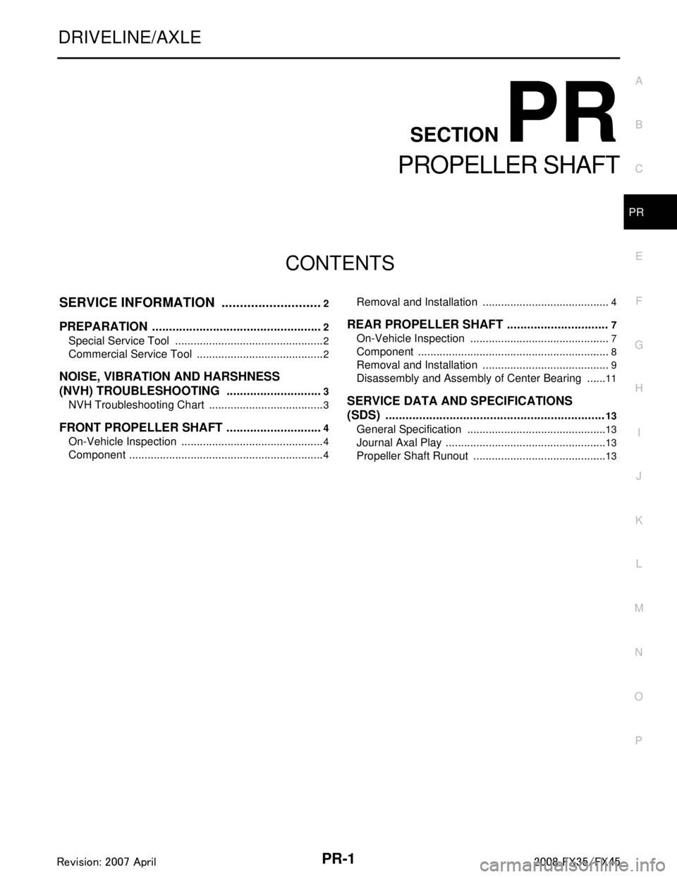
CONTENTS
PROPELLER SHAFT
SERVICE INFORMATION .. ..........................2
PREPARATION .............................................. .....2
Special Service Tool ........................................... ......2
Commercial Service Tool ..........................................2
NOISE, VIBRATION AND HARSHNESS
(NVH) TROUBLESHOOTING .............................
3
NVH Troubleshooting Chart ................................ ......3
FRONT PROPELLER SHAFT .............................4
On-Vehicle Inspection ......................................... ......4
Component ................................................................4
Removal and Installation ..................................... .....4
REAR PROPELLER SHAFT ..............................7
On-Vehicle Inspection ..............................................7
Component ...............................................................8
Removal and Installation ..........................................9
Disassembly and Assembly of Center Bearing .......11
SERVICE DATA AND SPECIFICATIONS
(SDS) .................................................................
13
General Specification ..............................................13
Journal Axal Play .....................................................13
Propeller Shaft Runout ............................................13
3AA93ABC3ACD3AC03ACA3AC03AC63AC53A913A773A893A873A873A8E3A773A983AC73AC93AC03AC3
3A893A873A873A8F3A773A9D3AAF3A8A3A8C3A863A9D3AAF3A8B3A8C
Page 3445 of 3924
NOISE, VIBRATION AND HARSHNESS (NVH) TROUBLESHOOTINGPR-3
< SERVICE INFORMATION >
CEF
G H
I
J
K L
M A
B
PR
N
O P
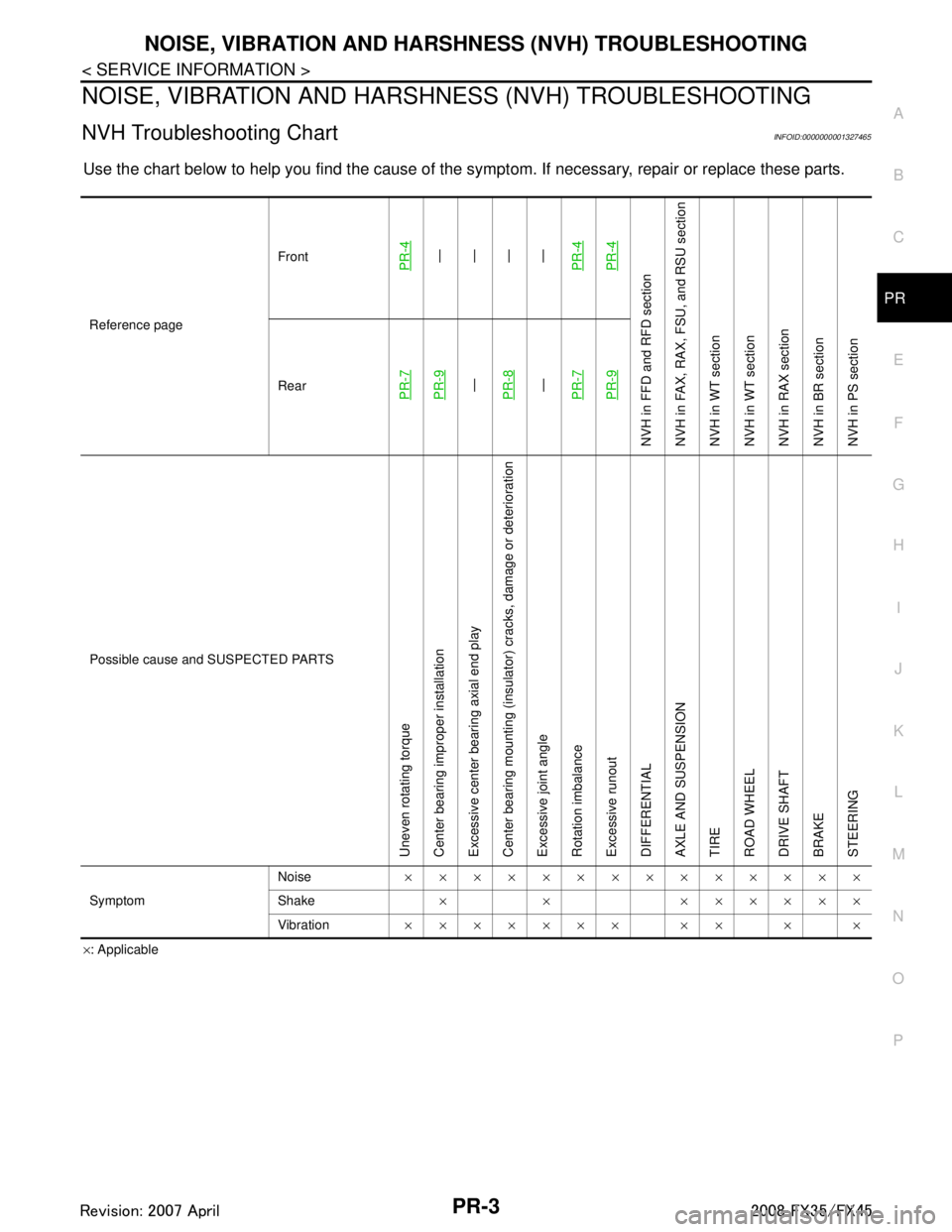
NOISE, VIBRATION AND HARSHN ESS (NVH) TROUBLESHOOTING
NVH Troubleshooting ChartINFOID:0000000001327465
Use the chart below to help you find t he cause of the symptom. If necessary, repair or replace these parts.
×: Applicable
Reference page
Front
PR-4—
—
—
—
PR-4PR-4
NVH in FFD an d RFD section
NVH in FAX, RAX, FS U, and RSU section
NVH in WT section
NVH in WT section
NVH in RAX section
NVH in BR section
NVH in PS section
RearPR-7PR-9—
PR-8—
PR-7PR-9
Possible cause and SUSPECTED PARTS
Uneven rotating torque
Center bearing improper installation
Excessive center bearing axial end play
Center bearing mounting (insulator) cracks, damage or deterioration
Excessive joint angle
Rotation imbalance
Excessive runout
DIFFERENTIAL
AXLE AND SUSPENSION
TIRE
ROAD WHEEL
DRIVE SHAFT
BRAKE
STEERING
Symptom Noise
××××××××××××××
Shake × × ××××××
Vibration ××××××× ×× × ×
3AA93ABC3ACD3AC03ACA3AC03AC63AC53A913A773A893A873A873A8E3A773A983AC73AC93AC03AC3
3A893A873A873A8F3A773A9D3AAF3A8A3A8C3A863A9D3AAF3A8B3A8C
Page 3456 of 3924

PS-1
STEERING
C
DE
F
H I
J
K L
M
SECTION PS
A
B
PS
N
O P
CONTENTS
POWER STEERING SYSTEM
SERVICE INFORMATION .. ..........................2
PRECAUTIONS .............................................. .....2
Precaution for Supplemental Restraint System
(SRS) "AIR BAG" and "SEAT BELT PRE-TEN-
SIONER" ............................................................. ......
2
Precaution Necessary for Steering Wheel Rota-
tion After Battery Disconnect .....................................
2
Precaution for Steering System ................................2
PREPARATION ...................................................4
Special Service Tool ........................................... ......4
Commercial Service Tool ..........................................5
NOISE, VIBRATION AND HARSHNESS
(NVH) TROUBLESHOOTING .............................
6
NVH Troubleshooting Chart ................................ ......6
POWER STEERING FLUID ................................7
Checking Fluid Level ........................................... ......7
Checking Fluid Leakage ............................................7
Air Bleeding Hydraulic System ..................................7
STEERING WHEEL .............................................9
On-Vehicle Inspection and Service ..................... ......9
Removal and Installation .........................................10
STEERING COLUMN .........................................12
Removal and Installation ..................................... ....12
Disassembly and Assembly .....................................14
POWER STEERING GEAR AND LINKAGE ....17
Removal and Installation .........................................17
Disassembly and Assembly .....................................19
POWER STEERING OIL PUMP .......................27
On-Vehicle Inspection and Service .........................27
Removal and Installation (VQ35DE Models) ...........28
Removal and Installation (VK45DE Models) ...........29
Disassembly and Assembly (VQ35DE Models) ......29
Disassembly and Assembly (VK45DE Models) .......32
HYDRAULIC LINE ............................................37
Component ..............................................................37
Removal and Installation .........................................39
SERVICE DATA AND SPECIFICATIONS
(SDS) .................................................................
41
Steering Wheel ........................................................41
Steering Angle .........................................................41
Steering Column ......................................................41
Steering Outer Socket and Inner Socket .................41
Steering Gear ..........................................................42
Oil Pump ..................................................................43
Steering Fluid ..........................................................43
3AA93ABC3ACD3AC03ACA3AC03AC63AC53A913A773A893A873A873A8E3A773A983AC73AC93AC03AC3
3A893A873A873A8F3A773A9D3AAF3A8A3A8C3A863A9D3AAF3A8B3A8C
Page 3461 of 3924
PS-6
< SERVICE INFORMATION >
NOISE, VIBRATION AND HARSHNESS (NVH) TROUBLESHOOTING
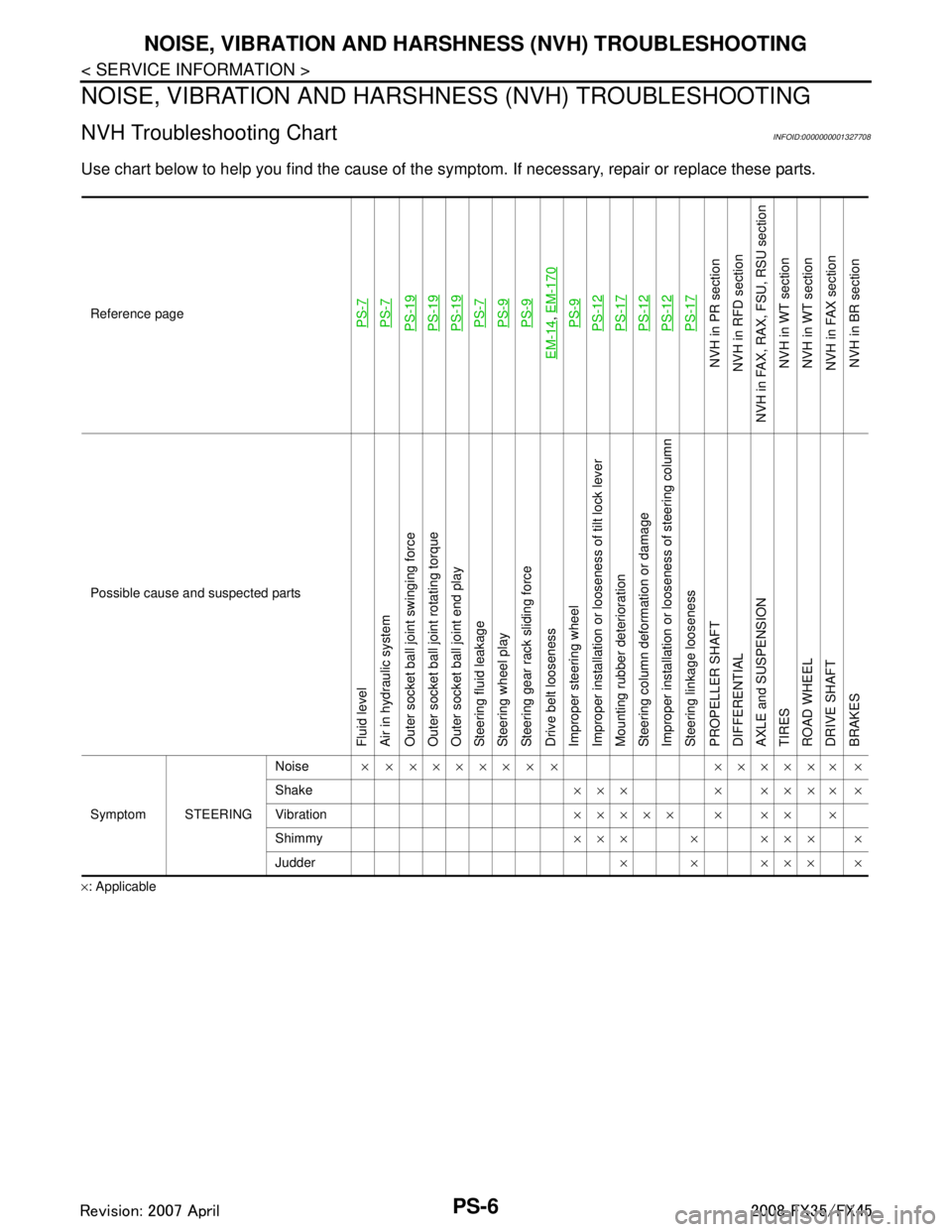
NOISE, VIBRATION AND HARSHNESS (NVH) TROUBLESHOOTING
NVH Troubleshooting ChartINFOID:0000000001327708
Use chart below to help you find the cause of the symp tom. If necessary, repair or replace these parts.
×: ApplicableReference page
PS-7PS-7PS-19PS-19PS-19PS-7PS-9PS-9
EM-14
,
EM-170PS-9PS-12PS-17PS-12PS-12PS-17
NVH in PR section
NVH in RFD section
NVH in FAX, RAX, FSU, RSU section NVH in WT section
NVH in WT section
NVH in FAX section
NVH in BR section
Possible cause and suspected parts
Fluid level
Air in hydraulic system
Outer socket ball joint swinging force
Outer socket ball joint rotating torque
Outer socket ball joint end play
Steering fluid leakage
Steering wheel play
Steering gear rack sliding force
Drive belt looseness
Improper steering wheel
Improper installation or looseness of tilt lock lever
Mounting rubber deterioration
Steering column deformation or damage
Improper installation or looseness of steering column
Steering linkage looseness
PROPELLER SHAFT
DIFFERENTIAL
AXLE and SUSPENSION
TIRES
ROAD WHEEL
DRIVE SHAFT
BRAKES
Symptom STEERING Noise
× × ××××× × × ×××××× ×
Shake ××× × ×××× ×
Vibration ××××× × ×× ×
Shimmy ××× × ××× ×
Judder ××××××
3AA93ABC3ACD3AC03ACA3AC03AC63AC53A913A773A893A873A873A8E3A773A983AC73AC93AC03AC3
3A893A873A873A8F3A773A9D3AAF3A8A3A8C3A863A9D3AAF3A8B3A8C
Page 3499 of 3924
RAX-1
DRIVELINE/AXLE
CEF
G H
I
J
K L
M
SECTION RAX
A
B
RAX
N
O P
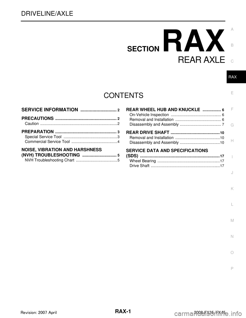
CONTENTS
REAR AXLE
SERVICE INFORMATION .. ..........................2
PRECAUTIONS .............................................. .....2
Caution ................................................................ ......2
PREPARATION ...................................................3
Special Service Tool ........................................... ......3
Commercial Service Tool ..........................................4
NOISE, VIBRATION AND HARSHNESS
(NVH) TROUBLESHOOTING .............................
5
NVH Troubleshooting Chart ................................ ......5
REAR WHEEL HUB AND KNUCKLE ...............6
On-Vehicle Inspection ......................................... .....6
Removal and Installation ..........................................6
Disassembly and Assembly ......................................7
REAR DRIVE SHAFT ........................................10
Removal and Installation .........................................10
Disassembly and Assembly .....................................10
SERVICE DATA AND SPECIFICATIONS
(SDS) .................................................................
17
Wheel Bearing .........................................................17
Drive Shaft ...............................................................17
3AA93ABC3ACD3AC03ACA3AC03AC63AC53A913A773A893A873A873A8E3A773A983AC73AC93AC03AC3
3A893A873A873A8F3A773A9D3AAF3A8A3A8C3A863A9D3AAF3A8B3A8C
Page 3503 of 3924
NOISE, VIBRATION AND HARSHNESS (NVH) TROUBLESHOOTINGRAX-5
< SERVICE INFORMATION >
CEF
G H
I
J
K L
M A
B
RAX
N
O P
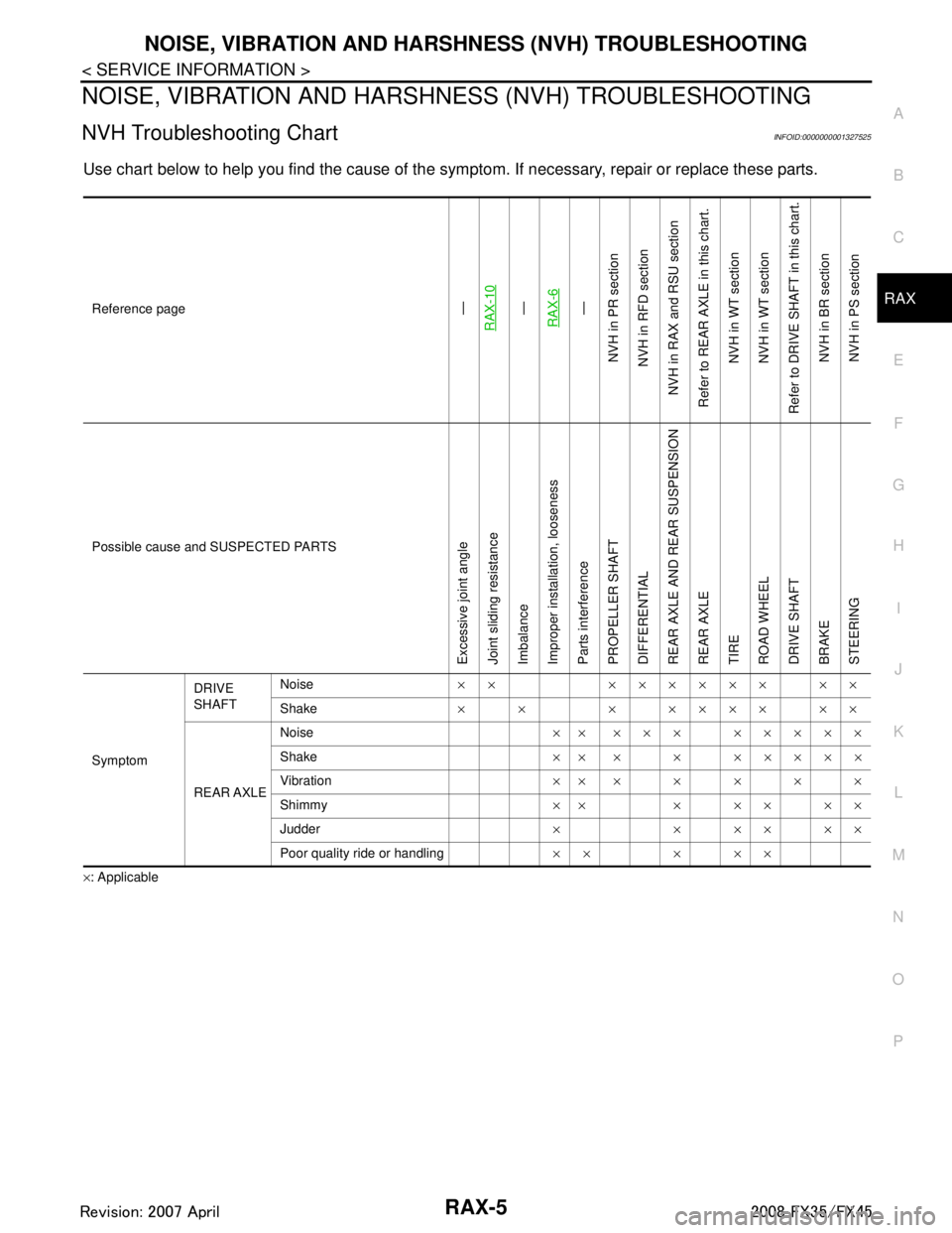
NOISE, VIBRATION AND HARSHN ESS (NVH) TROUBLESHOOTING
NVH Troubleshooting ChartINFOID:0000000001327525
Use chart below to help you find the cause of the symp tom. If necessary, repair or replace these parts.
×: ApplicableReference page
—
RAX-10—
RAX-6—
NVH in PR section
NVH in RFD section
NVH in RAX and RSU section
Refer to REAR AXLE in this chart. NVH in WT section
NVH in WT section
Refer to DRIVE SHAFT in this chart.
NVH in BR sectionNVH in PS section
Possible cause and SUSPECTED PARTS
Excessive joint angle
Joint sliding resistance
Imbalance
Improper installation, looseness
Parts interference
PROPELLER SHAFT
DIFFERENTIAL
REAR AXLE AND REAR SUSPENSION
REAR AXLE
TIRE
ROAD WHEEL
DRIVE SHAFT
BRAKE
STEERING
Symptom DRIVE
SHAFT
Noise
×× ×××××× ××
Shake × × × ×××× ××
REAR AXLE Noise
×× ××× ×××××
Shake ×× × × ×××××
Vibration ×××××××
Shimmy ×× × × × × ×
Judder × × ×× ××
Poor quality ride or handling ×× × ××
3AA93ABC3ACD3AC03ACA3AC03AC63AC53A913A773A893A873A873A8E3A773A983AC73AC93AC03AC3
3A893A873A873A8F3A773A9D3AAF3A8A3A8C3A863A9D3AAF3A8B3A8C
Page 3516 of 3924
RF-1
BODY
C
DE
F
G H
J
K L
M
SECTION RF
A
B
RF
N
O P
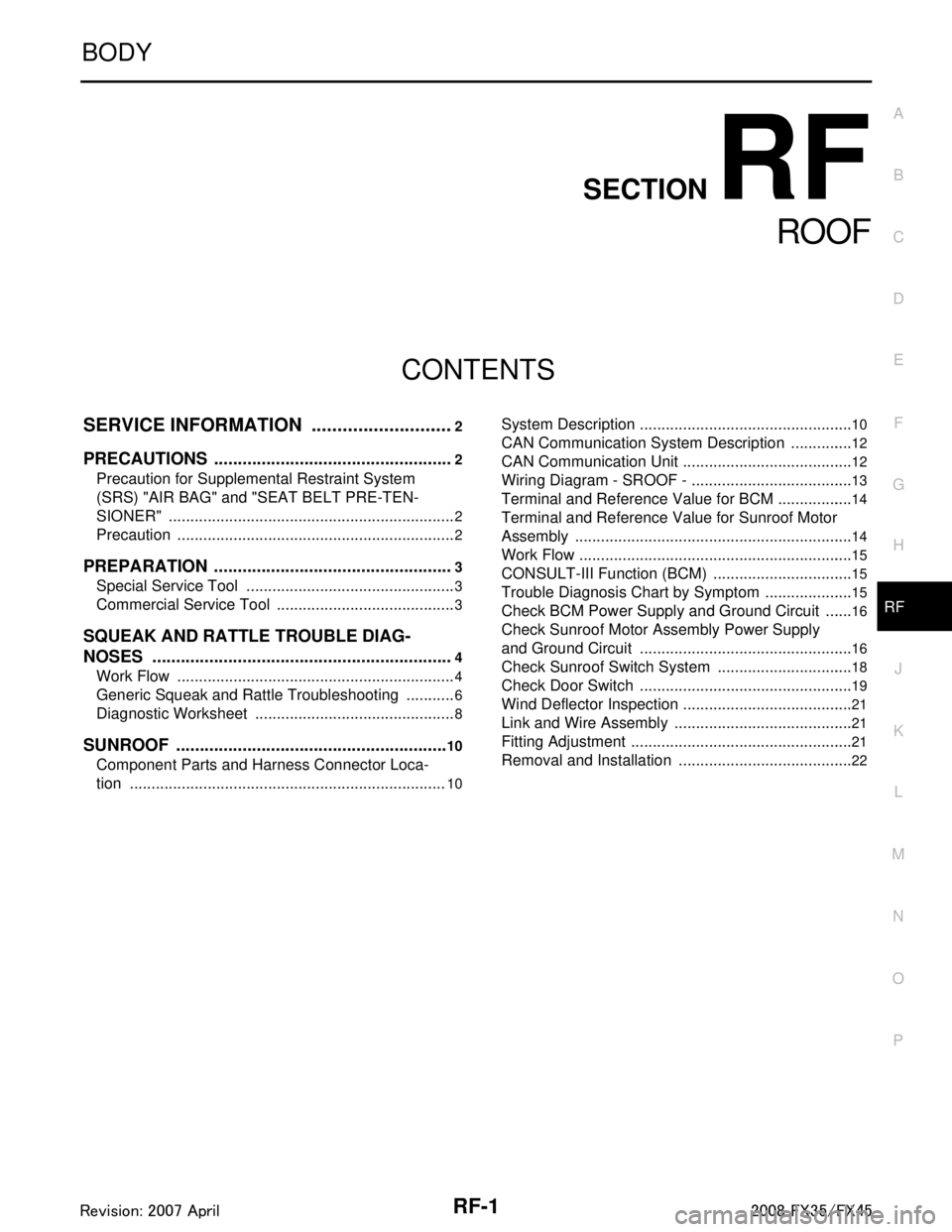
CONTENTS
ROOF
SERVICE INFORMATION .. ..........................2
PRECAUTIONS .............................................. .....2
Precaution for Supplemental Restraint System
(SRS) "AIR BAG" and "SEAT BELT PRE-TEN-
SIONER" ............................................................. ......
2
Precaution .................................................................2
PREPARATION ...................................................3
Special Service Tool ........................................... ......3
Commercial Service Tool ..........................................3
SQUEAK AND RATTLE TROUBLE DIAG-
NOSES ................................................................
4
Work Flow ........................................................... ......4
Generic Squeak and Rattle Troubleshooting ............6
Diagnostic Worksheet ...............................................8
SUNROOF ...................................................... ....10
Component Parts and Harness Connector Loca-
tion ...................................................................... ....
10
System Description .............................................. ....10
CAN Communication System Description ...............12
CAN Communication Unit ........................................12
Wiring Diagram - SROOF - ......................................13
Terminal and Reference Value for BCM ..................14
Terminal and Reference Value for Sunroof Motor
Assembly .................................................................
14
Work Flow ................................................................15
CONSULT-III Function (BCM) .................................15
Trouble Diagnosis Chart by Symptom .....................15
Check BCM Power Supply and Ground Circuit .......16
Check Sunroof Motor Assembly Power Supply
and Ground Circuit ..................................................
16
Check Sunroof Switch System ................................18
Check Door Switch ..................................................19
Wind Deflector Inspection ........................................21
Link and Wire Assembly ..........................................21
Fitting Adjustment ....................................................21
Removal and Installation .........................................22
3AA93ABC3ACD3AC03ACA3AC03AC63AC53A913A773A893A873A873A8E3A773A983AC73AC93AC03AC3
3A893A873A873A8F3A773A9D3AAF3A8A3A8C3A863A9D3AAF3A8B3A8C
Page 3543 of 3924
RFD-1
DRIVELINE/AXLE
CEF
G H
I
J
K L
M
SECTION RFD
A
B
RFD
N
O P
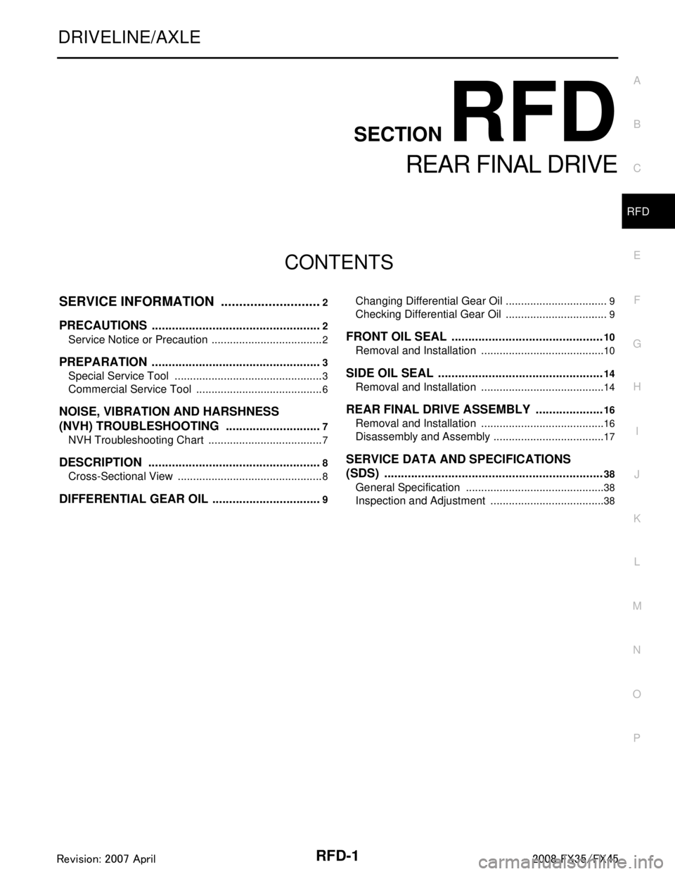
CONTENTS
REAR FINAL DRIVE
SERVICE INFORMATION .. ..........................2
PRECAUTIONS .............................................. .....2
Service Notice or Precaution ............................... ......2
PREPARATION ...................................................3
Special Service Tool ........................................... ......3
Commercial Service Tool ..........................................6
NOISE, VIBRATION AND HARSHNESS
(NVH) TROUBLESHOOTING .............................
7
NVH Troubleshooting Chart ................................ ......7
DESCRIPTION ....................................................8
Cross-Sectional View .......................................... ......8
DIFFERENTIAL GEAR OIL .................................9
Changing Differential Gear Oil ............................. .....9
Checking Differential Gear Oil ..................................9
FRONT OIL SEAL .............................................10
Removal and Installation .........................................10
SIDE OIL SEAL .................................................14
Removal and Installation .........................................14
REAR FINAL DRIVE ASSEMBLY ....................16
Removal and Installation .........................................16
Disassembly and Assembly .....................................17
SERVICE DATA AND SPECIFICATIONS
(SDS) .................................................................
38
General Specification ..............................................38
Inspection and Adjustment ......................................38
3AA93ABC3ACD3AC03ACA3AC03AC63AC53A913A773A893A873A873A8E3A773A983AC73AC93AC03AC3
3A893A873A873A8F3A773A9D3AAF3A8A3A8C3A863A9D3AAF3A8B3A8C