2008 INFINITI FX35 change time
[x] Cancel search: change timePage 3383 of 3924

IPDM E/R (INTELLIGENT POWER DISTRIBUTION MODULE ENGINE ROOM)
PG-19
< SERVICE INFORMATION >
C
D E
F
G H
I
J
L
M A
B
PG
N
O P
NOTE: The details for display of the period are as follows:
CRNT: Error currently de tected with IPDM E/R.
PAST: Error detected in the past and memorized with IPDM E/R.
DATA MONITOR
NOTE:
Perform monitoring of IPDM E/R data with the ignition switch ON. When the ignition switch is at ACC, the display may not be co rrect.
*1: The vehicle without the Intelligent Key system displays only ON without change.
*2:The cornering lamp item is displayed, but it cannot be monitored.
ACTIVE TEST
DTC Display Items Malfunction detecting condition TIME
Possible causes
CRNT PAST
— NO DTC IS DETECT-
ED.FURTHER TEST-
ING MAY BE
REQUIRED. ————
U1000 CAN COMM CIRCUIT If CAN communication reception/transmission
data has a malfunction, or if any of the control
units malfunction, data reception/transmission
cannot be confirmed.
When the data in CAN communication is not re- ceived before the specified time ××
Any of or several items
below have errors.
TRANSMIT DIAG
ECM
BCM/SEC
Item name
CONSULT-III screen dis-
play Display or unit MAIN SIG-
NALS Description
Motor fan request MOTOR FAN REQ 1/2/3/4 ×Signal status input from ECM
Compressor request A C COMP REQ On/Off ×Signal status input from ECM
Tail & clear request TAIL&CLR REQ On/Off ×Signal status input from BCM
H/L LO request HL LO REQ On/Off ×Signal status input from BCM
H/L HI request HL HI REQ On/Off ×Signal status input from BCM
FR fog request FR FOG REQ On/Off ×Signal status input from BCM
FR wiper request FR WIP REQ Stop/1LOW/Lo/Hi ×Signal status input from BCM
Wiper auto stop WIP AUTO STOP ACT P/STOP P ×Output status of IPDM E/R
Wiper protection WIP PROT Off/BLOCK ×Control status of IPDM E/R
Starter request ST RLY REQ
*1On/Off Status of input signal
Ignition relay status IGN RLY On/Off ×Ignition relay status monitored with
IPDM E/R
Rear window defogger re-
quest RR DEF REQ On/Off
×Signal status input from BCM
Oil pressure switch OIL P SW Open/Close Signal status input in IPDM E/R
Hood switch HOOD SW On/Off Input signal status
Theft warning horn re-
quest THFT HRN REQ On/Off Signal st
atus input from BCM
Horn chirp HORN CHIRP On/Off Ou tput status of IPDM E/R
Cornering lamp request CRNRNG LMP REQ
*2Off Signal status input from BCM
Test item CONSULT-III screen display Description
Tail lamp operation TAIL LAMP With a certain On-Off operation, the tail lamp relay can be operated.
Rear window defogger opera-
tion REAR DEFOGGER
With a certain On-Off operation, the rear window defogger relay can be
operated.
3AA93ABC3ACD3AC03ACA3AC03AC63AC53A913A773A893A873A873A8E3A773A983AC73AC93AC03AC3
3A893A873A873A8F3A773A9D3AAF3A8A3A8C3A863A9D3AAF3A8B3A8C
Page 3522 of 3924

SQUEAK AND RATTLE TROUBLE DIAGNOSESRF-7
< SERVICE INFORMATION >
C
DE
F
G H
J
K L
M A
B
RF
N
O P
Most of these incidents can be repaired by adjusting, se curing or insulating the item(s) or component(s) caus-
ing the noise.
SUNROOF/HEADLINING
Noises in the sunroof/headlining area can often be traced to one of the following:
1. Sunroof lid, rail, linkage or seals making a rattle or light knocking noise
2. Sunvisor shaft shaking in the holder
3. Front or rear windshield touching headlining and squeaking
Again, pressing on the components to stop the noise while duplicating the conditions can isolate most of these
incidents. Repairs usually consist of insulating with felt cloth tape.
SEATS
When isolating seat noise it's important to note the pos ition the seat is in and the load placed on the seat when
the noise is present. These conditions should be duplic ated when verifying and isolating the cause of the
noise.
Cause of seat noise include:
1. Headrest rods and holder
2. A squeak between the seat pad cushion and frame
3. Rear seatback lock and bracket
These noises can be isolated by moving or pressing on the suspected components while duplicating the con-
ditions under which the noise occurs. Most of thes e incidents can be repaired by repositioning the component
or applying urethane tape to the contact area.
UNDERHOOD
Some interior noise may be caused by components under the hood or on the engine wall. The noise is then
transmitted into the passenger compartment.
Causes of transmitted underhood noise include:
1. Any component mounted to the engine wall
2. Components that pass through the engine wall
3. Engine wall mounts and connectors
4. Loose radiator mounting pins
5. Hood bumpers out of adjustment
6. Hood striker out of adjustment
These noises can be difficult to isolate since they cannot be reached from the interior of the vehicle. The best
method is to secure, move or insulate one component at a time and test drive the vehicle. Also, engine RPM
or load can be changed to isolate the noise. Repairs c an usually be made by moving, adjusting, securing, or
insulating the component causing the noise.
3AA93ABC3ACD3AC03ACA3AC03AC63AC53A913A773A893A873A873A8E3A773A983AC73AC93AC03AC3
3A893A873A873A8F3A773A9D3AAF3A8A3A8C3A863A9D3AAF3A8B3A8C
Page 3530 of 3924
SUNROOFRF-15
< SERVICE INFORMATION >
C
DE
F
G H
J
K L
M A
B
RF
N
O P
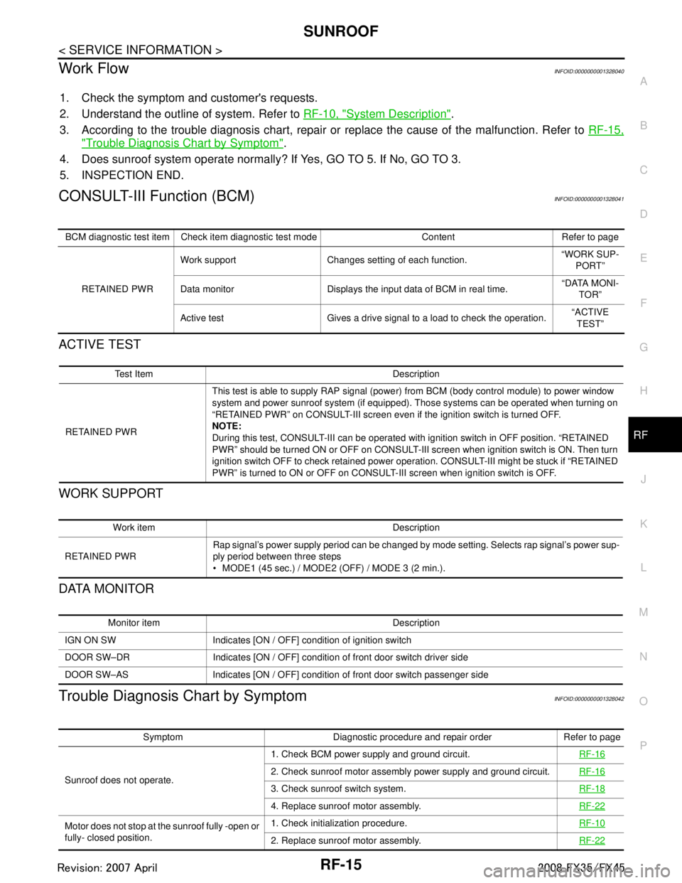
Work FlowINFOID:0000000001328040
1. Check the symptom and customer's requests.
2. Understand the outline of system. Refer to RF-10, "
System Description".
3. According to the trouble diagnosis chart, repair or replace the cause of the malfunction. Refer to RF-15,
"Trouble Diagnosis Chart by Symptom".
4. Does sunroof system operate normally? If Yes, GO TO 5. If No, GO TO 3.
5. INSPECTION END.
CONSULT-III Function (BCM)INFOID:0000000001328041
ACTIVE TEST
WORK SUPPORT
DATA MONITOR
Trouble Diagnosis Chart by SymptomINFOID:0000000001328042
BCM diagnostic test item Check item diagnostic test mode Content Refer to page
RETAINED PWR Work support Changes setting of each function.
“WORK SUP-
PORT”
Data monitor Displays the input data of BCM in real time. “DATA MONI-
TOR”
Active test Gives a drive signal to a load to check the operation. “ACTIVE
TEST”
Test Item Description
RETAINED PWR This test is able to supply RAP signal (powe
r) from BCM (body control module) to power window
system and power sunroof system (if equipped). Those systems can be operated when turning on
“RETAINED PWR” on CONSULT-III screen even if the ignition switch is turned OFF.
NOTE:
During this test, CONSULT-III can be operated with ignition switch in OFF position. “RETAINED
PWR” should be turned ON or OFF on CONSULT-III screen when ignition switch is ON. Then turn
ignition switch OFF to check retained power operation. CONSULT-III might be stuck if “RETAINED
PWR” is turned to ON or OFF on CONSULT- III screen when ignition switch is OFF.
Work item Description
RETAINED PWR Rap signal’s power supply period can be changed by mode setting. Selects rap signal’s power sup-
ply period between three steps
MODE1 (45 sec.) / MODE2 (OFF) / MODE 3 (2 min.).
Monitor item Description
IGN ON SW Indicates [ON / OFF] condition of ignition switch
DOOR SW–DR Indicates [ON / OFF] condition of front door switch driver side
DOOR SW–AS Indicates [ON / OFF] condition of front door switch passenger side
Symptom Diagnostic procedure and repair order Refer to page
Sunroof does not operate. 1. Check BCM power supply and ground circuit.
RF-16
2. Check sunroof motor assembly power supply and ground circuit.RF-16
3. Check sunroof switch system. RF-18
4. Replace sunroof motor assembly.RF-22
Motor does not stop at the sunroof fully -open or
fully- closed position.1. Check initialization procedure.
RF-10
2. Replace sunroof motor assembly.RF-22
3AA93ABC3ACD3AC03ACA3AC03AC63AC53A913A773A893A873A873A8E3A773A983AC73AC93AC03AC3
3A893A873A873A8F3A773A9D3AAF3A8A3A8C3A863A9D3AAF3A8B3A8C
Page 3648 of 3924

SQUEAK AND RATTLE TROUBLE DIAGNOSESSE-9
< SERVICE INFORMATION >
C
DE
F
G H
J
K L
M A
B
SE
N
O P
Most of these incidents can be repaired by adjusting, se curing or insulating the item(s) or component(s) caus-
ing the noise.
SUNROOF/HEADLINING
Noises in the sunroof/headlining area can often be traced to one of the following:
1. Sunroof lid, rail, linkage or seals making a rattle or light knocking noise
2. Sun-visor shaft shaking in the holder
3. Front or rear windshield touching headlining and squeaking
Again, pressing on the components to stop the noise while duplicating the conditions can isolate most of these
incidents. Repairs usually consist of insulating with felt cloth tape.
SEATS
When isolating seat noise it's important to note the pos ition the seat is in and the load placed on the seat when
the noise is present. These conditions should be duplic ated when verifying and isolating the cause of the
noise.
Cause of seat noise include:
1. Headrest rods and holder
2. A squeak between the seat pad cushion and frame
3. The rear seatback lock and bracket
These noises can be isolated by moving or pressing on the suspected components while duplicating the con-
ditions under which the noise occurs. Most of thes e incidents can be repaired by repositioning the component
or applying urethane tape to the contact area.
UNDERHOOD
Some interior noise may be caused by components under the hood or on the engine wall. The noise is then
transmitted into the passenger compartment.
Causes of transmitted under-hood noise include:
1. Any component mounted to the engine wall
2. Components that pass through the engine wall
3. Engine wall mounts and connectors
4. Loose radiator mounting pins
5. Hood bumpers out of adjustment
6. Hood striker out of adjustment
These noises can be difficult to isolate since they cannot be reached from the interior of the vehicle. The best
method is to secure, move or insulate one component at a time and test drive the vehicle. Also, engine RPM
or load can be changed to isolate the noise. Repairs c an usually be made by moving, adjusting, securing, or
insulating the component causing the noise.
3AA93ABC3ACD3AC03ACA3AC03AC63AC53A913A773A893A873A873A8E3A773A983AC73AC93AC03AC3
3A893A873A873A8F3A773A9D3AAF3A8A3A8C3A863A9D3AAF3A8B3A8C
Page 3679 of 3924
SE-40
< SERVICE INFORMATION >
AUTOMATIC DRIVE POSITIONER
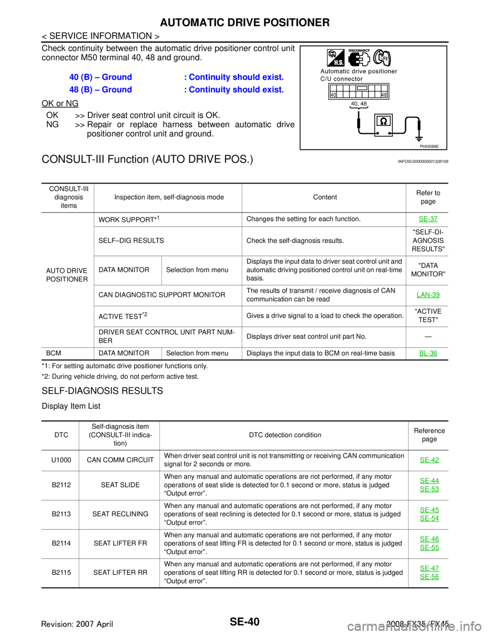
Check continuity between the automatic drive positioner control unit
connector M50 terminal 40, 48 and ground.
OK or NG
OK >> Driver seat control unit circuit is OK.
NG >> Repair or replace harness between automatic drive
positioner control unit and ground.
CONSULT-III Function (AUTO DRIVE POS.)INFOID:0000000001328108
*1: For setting automatic drive positioner functions only.
*2: During vehicle driving, do not perform active test.
SELF-DIAGNOSIS RESULTS
Display Item List
40 (B) – Ground : Continuity should exist.
48 (B) – Ground : Continuity should exist.
PIIA5088E
CONSULT-III
diagnosis items Inspection item, self-diagnosis mode Content
Refer to
page
AUTO DRIVE
POSITIONER WORK SUPPORT*
1Changes the setting for each function.
SE-37
SELF–DIG RESULTS Check the self-diagnosis results. "SELF-DI-
AGNOSIS
RESULTS"
DATA MONITOR Selection from menu Displays the input data to driver seat control unit and
automatic driving positioned control unit on real-time
basis. "DATA
MONITOR"
CAN DIAGNOSTIC SUPPORT MONITOR The results of transmit / receive diagnosis of CAN
communication can be read LAN-39
ACTIVE TEST*2Gives a drive signal to a load to check the operation.
"ACTIVE
TEST"
DRIVER SEAT CONTROL UNIT PART NUM-
BER Displays driver seat control unit part No. —
BCM DATA MONITOR Selection from menu Displays the input data to BCM on real-time basisBL-36
DTCSelf-diagnosis item
(CONSULT-III indica- tion) DTC detection condition
Reference
page
U1000 CAN COMM CIRCUIT When driver seat control unit is not transmitting or receiving CAN communication
signal for 2 seconds or more.
SE-42
B2112 SEAT SLIDEWhen any manual and automatic operations are not performed, if any motor
operations of seat slide is detected for 0.1 second or more, status is judged
“Output error”. SE-44SE-53
B2113 SEAT RECLINING
When any manual and automatic operations are not performed, if any motor
operations of seat reclining is detected for 0.1 second or more, status is judged
“Output error”. SE-45SE-54
B2114 SEAT LIFTER FR
When any manual and automatic operations are not performed, if any motor
operations of seat lifting FR is detected for 0.1 second or more, status is judged
“Output error”. SE-46SE-55
B2115 SEAT LIFTER RR
When any manual and automatic operations are not performed, if any motor
operations of seat lifting RR is detected for 0.1 second or more, status is judged
“Output error”. SE-47SE-56
3AA93ABC3ACD3AC03ACA3AC03AC63AC53A913A773A893A873A873A8E3A773A983AC73AC93AC03AC3
3A893A873A873A8F3A773A9D3AAF3A8A3A8C3A863A9D3AAF3A8B3A8C
Page 3759 of 3924
SRS-22
< SERVICE INFORMATION >
TROUBLE DIAGNOSIS
Diagnosis results previously stored in the memory are displayed on the CONSULT-III screen. The stored
results are not erased until memory erasing is executed.
“TROUBLE DIAG RECORD”
With TROUBLE DIAG RECORD, diagnosis results previ ously erased by a reset operation can be displayed
on the CONSULT-III screen.
“ECU DISCRIMINATED NO.”
The diagnosis sensor unit for each vehicle model is assigned with its own, individual classification number.
This number will be displayed on the CONSULT-III scr een, as shown. When replacing the diagnosis sensor
unit, refer to the part number for the compatibility. Af ter installation, replacement with a correct unit can be
checked by confirming this classification number on the CONSULT-III screen.
After repair, make sure the discriminated number of diagnosis sensor unit installed to vehicle are same.
Refer to SRS-44, "
Removal and Installation".
HOW TO CHANGE SELF-DIAGNOSIS MODE WITH CONSULT-III
From User Mode to Diagnosis Mode
After selecting “AIR BAG” on the “SELECT SYSTEM” screen, User mode automatically changes to Diagnosis
mode.
From Diagnosis Mode to User Mode
To return to User mode from Diagnosis mode, touch “BACK” key of CONSULT-III until “SELECT SYSTEM”
appears, then diagnosis mode automat ically changes to User mode.
HOW TO ERASE SELF-DIAGNOSTIC RESULTS
“SELF-DIAG [CURRENT]”
A current self-diagnostic result is displayed on the CONSULT-III screen in real time.
After the malfunction is repaired completely, no malfunction is detected on “SELF-DIAG [CURRENT]”.
“SELF-DIAG [PAST]” Return to the “SELF-DIAG [CURRENT]” CONSULT-III screen by touching “BACK” key of CONSULT-III and
select “SELF-DIAG [CURRENT]” in SELECT DIAG MODE. Touch “ERASE” in “SELF-DIAG [CURRENT]”
mode.
NOTE:
If the memory of the malfunction in “SELF-DIAG [P AST]” is not erased, the User mode shows the system
malfunction by the operation of the warning lamp even if the malfunction is repaired completely.
“TROUBLE DIAG RECORD”
The memory of “TROUBLE DI AG RECORD” cannot be erased.
Self-Diagnosis Function (Without CONSULT-III)INFOID:0000000001524166
The reading of these results is accomplished “User mode” and “Diagnosis mode”.
After a malfunction is repaired, turn ignition switch ON. Diagnosis mode returns to the User mode. At that
time, the self-diagnostic result is cleared.
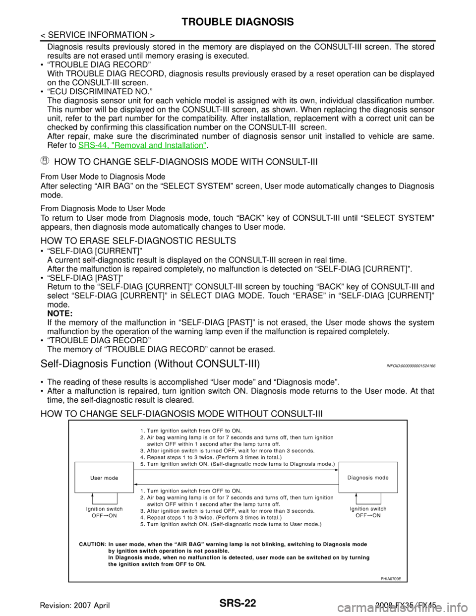
HOW TO CHANGE SELF-DIAGNOSIS MODE WITHOUT CONSULT-III
PHIA0709E
3AA93ABC3ACD3AC03ACA3AC03AC63AC53A913A773A893A873A873A8E3A773A983AC73AC93AC03AC3
3A893A873A873A8F3A773A9D3AAF3A8A3A8C3A863A9D3AAF3A8B3A8C
Page 3797 of 3924
AWD SYSTEMTF-11
< SERVICE INFORMATION >
CEF
G H
I
J
K L
M A
B
TF
N
O P
AWD SYSTEM
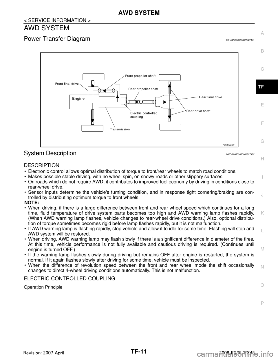
Power Transfer DiagramINFOID:0000000001327431
System DescriptionINFOID:0000000001327432
DESCRIPTION
Electronic control allows optimal distribution of torque to front/rear wheels to match road conditions.
Makes possible stable driving, with no wheel sp in, on snowy roads or other slippery surfaces.
On roads which do not require AWD, it contributes to improved fuel economy by driving in conditions close to
rear-wheel drive.
Sensor inputs determine the vehicle's turning conditi on, and in response tight cornering/braking are con-
trolled by distributing optimum torque to front wheels.
NOTE:
When driving, if there is a large difference between front and rear wheel speed which continues for a long
time, fluid temperature of drive system parts becom es too high and AWD warning lamp flashes rapidly.
(When AWD warning lamp flashes, vehicle changes to r ear-wheel drive conditions.) Also, optional distribu-
tion of torque sometimes becomes rigid before lamp flashes rapidly, but it is not malfunction.
If AWD warning lamp is flashing rapidly, stop vehicle and allow it to idle for some time. Flashing will stop and AWD system will be restored.
When driving, AWD warning lamp may flash slowly if ther e is a significant difference in diameter of the tires.
At this time, vehicle performance is not fully avail able and cautious driving is required. (Continues until
engine is turned OFF.)
If the warning lamp flashes slowly during driving but remains OFF after engine is restarted, the system is
normal. If it again flashes slowly after driving for some time, vehicle must be inspected.
When the difference of revolution speed between the front and rear wheel mode the shift occasionally
changes to direct 4-wheel driving conditions automatically. This is not malfunction.
ELECTRIC CONTROLLED COUPLING
Operation Principle
SDIA1611E
3AA93ABC3ACD3AC03ACA3AC03AC63AC53A913A773A893A873A873A8E3A773A983AC73AC93AC03AC3
3A893A873A873A8F3A773A9D3AAF3A8A3A8C3A863A9D3AAF3A8B3A8C
Page 3798 of 3924
TF-12
< SERVICE INFORMATION >
AWD SYSTEM
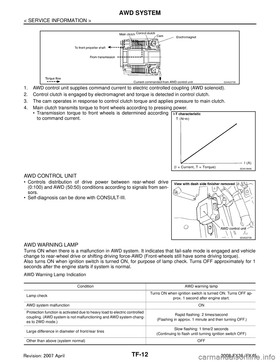
1. AWD control unit supplies command current to electric controlled coupling (AWD solenoid).
2. Control clutch is engaged by electromagnet and torque is detected in control clutch.
3. The cam operates in response to control clutch torque and applies pressure to main clutch.
4. Main clutch transmits torque to front wheels according to pressing power. Transmission torque to front wheels is determined accordingto command current.
AWD CONTROL UNIT
Controls distribution of drive power between rear-wheel drive(0:100) and AWD (50:50) conditions according to signals from sen-
sors.
Self-diagnosis can be done with CONSULT-III.
AWD WARNING LAMP
Turns ON when there is a malfunction in AWD system. It indicates that fail-safe mode is engaged and vehicle
change to rear-wheel drive or shifting driving force- AWD (Front-wheels still have some driving torque).
Also turns ON when ignition switch is turned ON, for purpose of lamp check. Turns OFF approximately for 1
seconds after the engine starts if system is normal.
AWD Warning Lamp Indication
SDIA2270E
SDIA1844E
SDIA2273E
Condition AWD warning lamp
Lamp check Turns ON when ignition switch is turned ON. Turns OFF ap-
prox. 1 second after engine start.
AWD system malfunction ON
Protection function is activated due to heavy load to electric controlled
coupling. (AWD system is not malfunctioning and AWD system chang-
es to 2WD mode.) Rapid flashing: 2 times/second
(Flashing in approx. 1 minute and then turning OFF.)
Large difference in diameter of front/rear tires Slow flashing: 1 time/2 seconds
(Continuing to flash until turning ignition switch OFF)
Other than above (system normal) OFF
3AA93ABC3ACD3AC03ACA3AC03AC63AC53A913A773A893A873A873A8E3A773A983AC73AC93AC03AC3
3A893A873A873A8F3A773A9D3AAF3A8A3A8C3A863A9D3AAF3A8B3A8C