2008 GREAT WALL FLORID airbag off
[x] Cancel search: airbag offPage 21 of 281

Downloaded from www.Manualslib.com manuals search engine GWFLORID Maintenance Manual14
Chassis' Main Assembly Technical Parameters (Continued)
ItemSpecifications
Wheel and
tire
Wheel specificationsStandard 15 × 6J rim, offset distance: 40 mm
Tire specificationsStandard tire selection 185/65 R15 88H
Spare tire
specificationsSpare tire 185/65 R15 88H, T125/70R16 96M J16 × 4T
Steering
system
Steering gearRack and pinion hydraulic power steering gear, with drive ratio of 19.03,
power steering pump rate of flow is 6.7-8.9 L/min
Steering columnSafe, energy absorbing, angle-adjustable steering column, with an adjustable
range of 3.6°.
Steering wheelA three stage softening type with airbag, diameter of 370 mm, and maximum
steering circle number of 3.08.
Main technical
parameters
Front wheel camber/rear wheel camber-0° 43′ ± 30′ /-0° 43' ± 30'
Kingpin angle+10°21′ ± 30′
Kingpin caster+1°49′ ± 30′
Front wheel toe-in/rear wheel toe-in-0° 01′ ± 15′ /+0° 14' ± 15'
Inside wheel steering angle (°)32°-37°
Outer wheel steering angle (°)28°-30°
Steering wheel rotation number (n)3.08
Steering system angle ratio (i0ω)19.03
Brake
system
Service brake type
The service brake system adopts a hydraulic vacuum power-assisted type.
The front/rear brakes are disc and drum brakes respectively. The front brake
uses a ventilated disc, and the brake pedal is a suspended pedal with vacuum
booster. Brake line is in a dual-circuit diagonal (X type) arrangement,
adopting a ABS + EBD anti-lock and braking force distribution system.
Service brake booster
and master cylinder
Single stage Φ9inch vacuum booster, series dual-chamber brake master
cylinder, cylinder bore Φ22.22 mm, stroke 32 mm
Brake reservoirShares with the clutch master cylinder reservoir and installed with a brake
fluid level alarm.
Brake pedal strokeFree play: 6-9 mm, working stroke: 37-40 mm.
Brake pedal pressure<380 N (no load) <480 N (full load)
Parking brake
The parking brake system uses a mechanical remote ratchet cable control
mechanism to control the rear wheel drum brake. Brake lever's functional
stroke is 5-8 gearteeth.
Brake parameters
Front wheelFloating caliper disc brake
Wheel cylinder
diameterΦ54 mm
Brake disc
diameterΦ255 mm
Rear wheelLeading trailing shoe drum
brake
Wheel cylinder
diameterΦ19.05 mm
Drum brake
diameterΦ200 mm
Page 151 of 281

Downloaded from www.Manualslib.com manuals search engine GWFLORID Maintenance Manual144
Double-colored wire: Primary color is Red, secondary color is Blue, mark\
ed as RBl.
0.5BrGr means Brown wire with a Gray fine wire, and sectional area is 0.\
5 mm2.
Areas of importance in circuit maintenance
1. Before operating any electronic devices, and when tools or maintenance devices may easily make
contact with an uncovered electronic terminal, please make sure to turn the ignition switch to the LOCK
position, and then disconnect the battery's negative cable to avoid injury or vehicle damage. When the
ignition switch is on the ON position, please do not disconnect the battery's connecting wire or take out
the power's fuse, regardless if the engine is running or not.Otherwise it would seriously damage the
ECU and related microelectronic devices such as sensors.
2. When changing the fuse, please make sure that the new fuse possesses the proper current rating,
and is not above or below this rating.
3. When repairing the wire harnesses of the airbag and pretensioner, only specified contact points,
plugs, and wires are allowed to be used.
4. Before repairing the wire harness, make sure to eliminate any factor that might cause damage,
for example, the edge of a vehicle body part is too sharp, or the used electronics are damaged or
corroded.
5. Shielded wire should not be repaired, it must be replaced entirely once it is damaged.
6. Unless it is specified during the test, please do not use an analog multimeter to test the ECU and
sensor, instead use a high-impedance digital multimeter (internal resistance should be ≥10 kΩ) or a
vehicle multimeter for inspection.
7. When inspecting the connector with a digital multimeter, take the waterproof rubber cover off the
connector, and tightly insert the test pen along the connecting terminal. Don't use too much force, as
to avoid cracking the connector.
Circuit inspection steps
The principle of troubleshooting is to confirm the "possible cause". Once the possible cause is confirmed, the
components that need to be inspected are limited to the components that are related to the possible cause. The
confirmed possible cause should be based on theory and be supported by facts, but not just by intuition. If
one tries to solve the problem but does not adopt the proper troubleshooting steps, it may make the problem
worse. Then the possible cause not only can't be confirmed, but also maintenance can't be performed properly.
Troubleshooting should adhere to the four steps below:
1. Observe the symptoms carefully, inspect if there is anything else abnormal, and record it.
2. While confirming the possible causes, study the circuit diagram carefully, and regard it as a whole
system in order to understand the circuit. Thorough knowledge of switches, relays, and other
electronic components is obligatory for proper analysis.
3. Inspect and eliminate the problems one by one until the cause is found.
4. After the malfunction is fixed, make sure to check if the inspected system is working properly, and also
check if the maintenance may have caused any new problems.
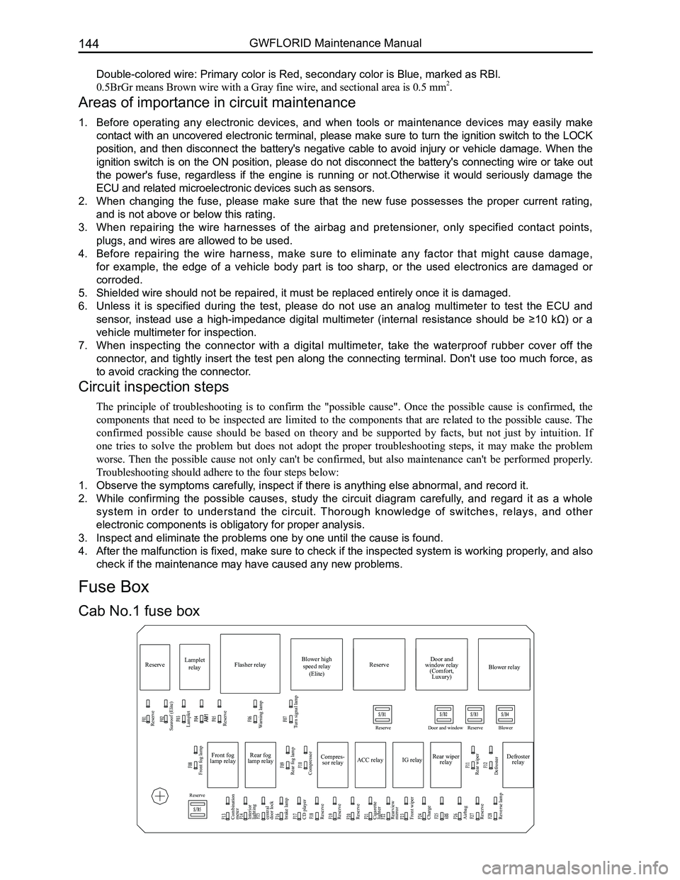
Compres-
sor relay
Reserve
Sunroof (Elite) Lamplet
Reserve
Reserve
Reserve
Reserve Door and window Reserve Blower
Lamplet
relay Flasher relay Blower high
speed relay (Elite) Door and
window relay (Comfort, Luxury) Blower relay
Reserve
Front fog lamp
Combination
meter
Interior
lighting
central
door lock
brake lamp
CD player
Reserve
Reserve
Reserve
Cigarette
lighter
Rearview
mirror
Front wiper
Charge
Airbag
Reserve
Reverse lamp Rear fog lamp
Rear wiper
Defroster Compressor
ACC relay
IG relayRear wiper
relay Defroster
relay
Front fog
lamp relay Rear fog
lamp relay
Warning lamp
Turn signal lamp
Cab No.1 fuse box
Fuse Box
Page 181 of 281

Downloaded from www.Manualslib.com manuals search engine GWFLORID Maintenance Manual174
Central door locking, window regulator system
Rise
Off
Descend
Rise
Off
Descend
Rise
Off
Descend
Front door switch RH
Rear door switch LH
Rear door switch RH
Jam protection window regulator control system
Front window regulator mainly switch LH
Front door jam
protection motor LHFront door jam
protection motor RHRear door jam
protection motor LH Rear door jam
protection motor RH
Connected combination meter
Connected combination meter
Connected combination meter
Connected high beam relay
Connected airbag ECU
Central control module
Connected interior dome lamp Connected reading lamp
Open door indicator lamp
Airbag signal
Back door lamp switch
Rear door lamp switch LH
Rear door lamp switch RH
Front door lamp switch RH
Front door lamp switch LH
Trunk opener switch
Trunk motor
Unlock
signal
Lock signalFront door lock LH Lock
UnlockRise
Off
Descend
Rise
Off
Descend
Rise
Off
Descend
Rise
Off
Descend
Rise
Off
Descend
Rise
Off
Descend
Rise
Off
Descend
Rise
Off
Descend
Rise
Off
Descend
Rise
Off
DescendDoor lock is
locked
Stationary
state
Door lock is
on
Front door lock
motor RH
Rear door lock
motor LH
Rear door lock
motor RH
Left turn signal
Right turn signal
Lighting detect
Passenger side central ocntrol switch Central ocntrol switch
Driver side electric switch Window lock switch
Front door electric
switch RH
Rear door electric
switch LH
Rear door electric
switch RH
Window relay
Window lock switch
Front door switch RH
Rear door switch LH
Rear door switch RH Door electric door
mainly control switch
Front door electric
switch RH
Rear door electric
switch LH
Rear door electric
switch RH
Non jam protection window regulator control system
Front door motor LH
Connected central door
lock controller (white)
Connected front
window regulator LH Connected rear window regulator LH
(comfort, luxury) Connected rear window regulator RH (Elite)
Connected rear window
regulator RH (comfort, luxury)Front window regulator LH
Rear door lock motor LHRear door lock motor RHBack door lamp ONBack door open switch Back door lock motor
Front window regulator RH
Connected front
window regulator RH
Connected rear
window regulator LHConnected rear
window regulator RH Connected rear
window regulator LH Rear window regulator RH
Front door lamp
switch LHFront door lamp
switch RHRear door lamp
switch LHRear door lamp
switch RH Front door lock motor LH
Front door lock motor RHThe key is inserted into the
detected switch
Window regulator mainly switch, central door lock mainly
control switch (comfort, luxury) Window regulator mainly switch, central door lock
mainly control switch (Elite)Connected front passenger side
central door lock switchFront window regulator switch RH (Elite)
Connected front window regulator switch
RH (comfort, luxury) Connected front window regulator switch
RH (comfort, luxury)Connected rear window regulator switch
LH (Elite)
Front door motor RH
Rear door motor LHRear door motor RH
Front window regulator mainly control switch LH
Terminal
Location
Terminal
Location
Page 221 of 281

Downloaded from www.Manualslib.com manuals search engine GWFLORID Maintenance Manual214
Areas of Importance
1. While performing maintenance on the SRS airbag, make sure to work in accordance with this
chapter's steps and notes.
2. Be sure to use the specified test apparatus and SST (Special Service Tools) which are mentioned in this
chapter.
3. While performing maintenance on the following mentioned components, if there is any problem with a
component, be sure to replace it with a new one.
• Airbag ECU assembly.
• Clock spring assembly.
• Driver side airbag assembly.
• Front passenger side airbag module.
• Driver side preload seat belt.
• Front passenger side preload seat belt.
• Airbag wire harness.
4. While performing maintenance, please disconnect the battery's negative terminal connector, and then
after waiting for 60 s, commence operation. Furthermore, wrap up the removed negative terminal with
insulating tape.
After the battery power is cut off, the capacitor in the airbag ECU will still maintain a set amount of electrical
energy. If used without waiting a sufficient amount of time, it may lead to serious injury and accidents due to
the airbag's faulty deployment.
5. When painting the vehicle, excessive heat may influence the components, in which case the SRS-ECU,
airbag module, clock spring, etc., should first be removed and set aside\
.
Use a diagnostic scanner to clear the trouble code after the SRS airbag is repaired, as to ensure the warning
lamp will continue to work normaly.
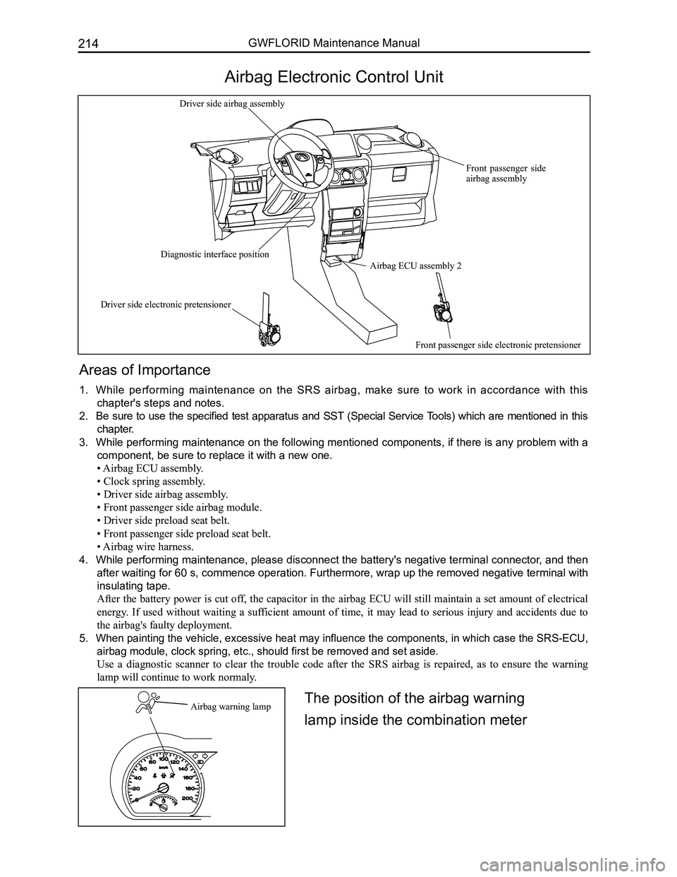
Airbag Electronic Control Unit
Airbag warning lamp
Airbag ECU assembly 2
Front passenger side airbag assembly
Driver side airbag assembly
Diagnostic interface position
Driver side electronic pretensioner
Front passenger side electronic pretensioner
The position of the airbag warning
lamp inside the combination meter
Page 223 of 281

Downloaded from www.Manualslib.com manuals search engine GWFLORID Maintenance Manual216
SRS airbag warning lamp inspection
1. When the ignition switch is set to the ON position, check if the SRS warning lamp remains on for 6-7 s.
2. If the SRS warning lamp shuts off after 6-7 s, this is normal.
3. Except for the items listed above, diagnostic inspection is still needed\
.
System diagnosis
Airbag ECU will initiate a series of diagnostic test cycles to check if the airbag system functions are ready for
use. This diagnostic test can guard against the restraint system's faulty execution and at the same time guarantee
prompt execution in a collision. If a malfunction appears, airbag ECU will store the appropriate trouble code and
light up the warning lamp to point out the malfunction, as to make maint\
enance more convenient.
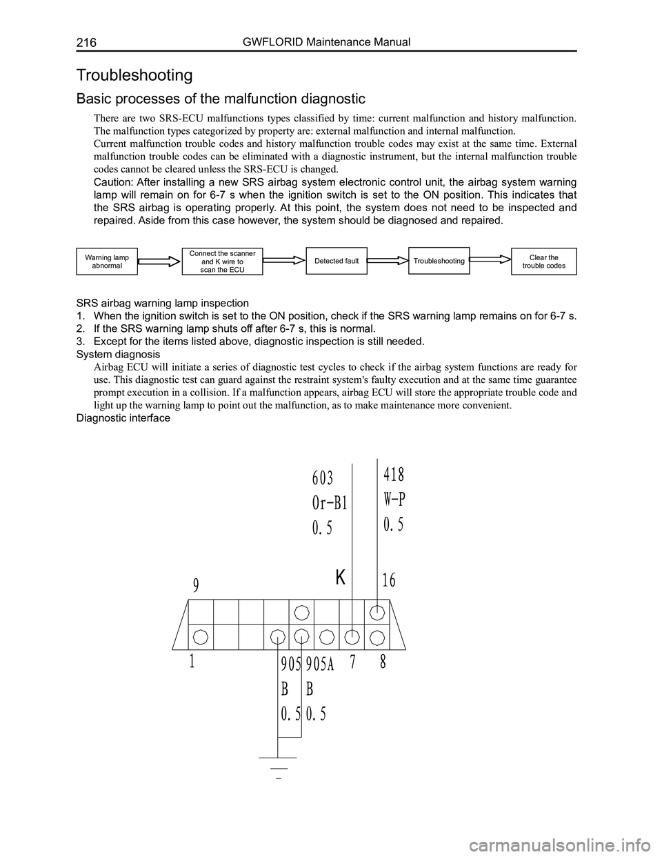
Diagnostic interface
Troubleshooting
Basic processes of the malfunction diagnostic
There are two SRS-ECU malfunctions types classified by time: current malfunction and history malfunction.
The malfunction types categorized by property are: external malfunction \
and internal malfunction.
Current malfunction trouble codes and history malfunction trouble codes may exist at the same time. External
malfunction trouble codes can be eliminated with a diagnostic instrument, but the internal malfunction trouble
codes cannot be cleared unless the SRS-ECU is changed.
Caution: After installing a new SRS airbag system electronic control unit, the airbag system warning
lamp will remain on for 6-7 s when the ignition switch is set to the ON position. This indicates that
the SRS airbag is operating properly. At this point, the system does not need to be inspected and
repaired. Aside from this case however, the system should be diagnosed and repaired.
Warning lampabnormal
Connect the scannerand K wire to scan the ECUDetected faultTroubleshooting Clear the trouble codes
Page 225 of 281

Downloaded from www.Manualslib.com manuals search engine GWFLORID Maintenance Manual218
detection but also during the diagnostic detection cycle. However, if a short circuit on the power supply causes
a malfunction, and the low-end transistor is opened while malfunctioned, the low-end transistor can only be
detected when starting up detection, as to avoid faulty execution.
(b) Ignition voltage is provided by a pressure increase converter.
(c) Acceleration sensor performs self-detection when starting up detection.
(d) Allowed offset range of the acceleration sensor during a diagnostic cycle.
(e) Microcontroller includes AD converter, ROM, RAM, etc.
(f) Security sensor status.
Caution: There is a short-circuiting bar inside the squib circuit connector. When the connector is not
connected, the short circuit happens between the squib circuit's terminal (+) and terminal (-), as to
avoid faulty deployment caused by static electricity. When the connector is bad and the short-circuiting
bar is connected, the fault symptom may not be eliminated.
4. Clear the trouble code
When the X-431 diagnostic instrument receives the "Clear the trouble code" order sent through the serial inter-
face, the trouble code inside the ECU will be cleared. However, if an internal trouble code is recorded or has a
collision record, it will not carry out this order.
(a) Malfunction status display.
When the working voltage is supplied to the SRS-ECU through a battery, the SRS-ECU will light the warning
lamp to inspect the light bulbs. During the initialization stage, the warning lamp will remain on for 6-7 s, and
in order to inform the driver that the system has a malfunction, the warning lamp will continue to remain on
after the working voltage is supplied. If the history trouble code’s quantity is less than 16, the warning lamp
will remain lit for 6-7 s after turning the ignition on and then turn off automatically. If the history trouble code’s
quantity is 16 and the current malfunction appears, it will be recorded and the first history malfunction record
will be automatically removed.
(b) Malfunction indicator.
When the system has malfunctioned, the warning lamp will be always on.
A displayed or history malfunction can only be reset by service personnel. A SRS-ECU internal malfunction or
malfunction’s "collision record" cannot be reset. In this situation, the SRS-ECU mus\
t be replaced.
(c) Microcontroller - independent warning lamp is lit.
The controller has a self-diagnosis function. If the inner controller malfunctions, the warning lamp will always
be on.
(d) If the airbag warning lamp is always on, please inspect it according to the following steps.
The first step of inspecting any of the malfunctions is to detect the malfunction’s position with a scanner. Then
carry out the inspection using the corresponding part’s inspection method. If the scanning result is an internal
malfunction or having to do with airbag execution, the SRS-ECU can be di\
rectly replaced.
Page 231 of 281

Downloaded from www.Manualslib.com manuals search engine GWFLORID Maintenance Manual224
StepsInspectionOperation
7
Inspect the clock spring
Take the clock spring off
See also airbag system and clock spring removal/
installation
Inspect the clock spring
See also airbag system and clock spring inspection
Check the clock spring. Is it normal?
NormalGo to the next step
Abnormal
Replace the clock spring
See also airbag system and clock
spring removal/installation
8
Check the wire harness between the clock spring and
SRS electronic control unit
Set the ignition switch to the "LOCK" position
Loosen the battery's negative cable and then wait for at
least 1 min
Take the glove box off (with the front passenger side
airbag)
L o o s e n t h e f r o n t p a s s e n g e r s i d e a i r b a g m o d u l e
connectors
Take out the dashboard base
Loosen all the SRS airbag system unit connectors
Check the wire harness of the connectors' terminal
studs between the SRS electronic control unit and the
clock spring to see whether they have the following
problems.
• Ground
• Short connected with the power supply
• Open circuit
Is the above wire harness normal?
Normal
Replace the driver side
airbag module
See also SRS airbag system
Driver side airbag module
removal/installation
AbnormalReplace the wire harness
7. Front passenger side malfunction
Type code 02
Trouble code
01, 02, 03
Front passenger side airbag module (resistance too low or too high, sho\
rt circuit, or grounded)
Detecting
conditions
Warning
• If not handled properly, the airbag module and stretch tension type seat belt may open or tense up,
causing serious operator injury. Therefore, before performing maintenance, please read the mainte-
nance warnings carefully.
See also airbag system maintenance warning
If there is a front passenger side airbag
• The resistance between the SRS airbag system unit connector's 3 and 4 pin is out of the specified
range
• The wire harness between the SRS airbag system unit connector’s 3 and 4 pins is short-circuited
• The SRS airbag system unit connector's 1 and 2, and 3 and 4 pins are open-circuited, if there is no
front passenger side airbag
Possible
causes
• Front passenger side airbag module malfunction
• Connector between the front passenger side airbag module and the SRS airbag system electronic
control unit malfunction
• Connectors between the SRS airbag system unit and the grounded point malfunction
• Circuit between the front passenger side airbag module and the SRS airbag system electronic control
unit is broken or short circuited
• Circuit between the SRS airbag system unit and the grounded point is broken or short circuited
• SRS airbag system unit malfunction
Page 232 of 281

Downloaded from www.Manualslib.com manuals search engine 225Airbags
Diagnostic procedures
StepsInspectionOperation
1Is the vehicle equipped with a front passenger side
airbag module?
YesGo to the next step
NoLine fault, inspect the wire harness
2
Check the front passenger side airbag module connec-
tor warning
• If not handled properly, the airbag module may deploy
and cause serious operator injury. Therefore, before
maintenance, please read the maintenance warnings
carefully.
See also airbag system maintenance warning
Set the ignition switch to the "LOCK" position
Loosen the battery's negative cable and wait for at least
1 min
Take the glove box off
Loosen the front passenger side airbag module connec-
tors
Is the front passenger side airbag module connector
normal?
Normal
[Current trouble code]
Go to the next step
[History trouble code]
Go to the next step
AbnormalReplace the wire harness
3
Check whether the malfunction is on the front passen-
ger side airbag module or the other components
Connect a good module with the front passenger side
airbag module connector's A and B terminal studs
Connect the battery's negative cable
Set the ignition switch to the "ON" position
Is a trouble code displayed?
YesGo to the next step
No
Replace the front passenger side
airbag module
See also airbag system and front
passenger side airbag module re-
moval/installation
4
Inspect the wire harness between front passenger side
airbag module and SRS airbag system electronic con-
trol unit
Set the ignition switch to the "LOCK" position
Loosen the battery's negative cable and then wait for at
least 1 min
Take the steering column housing off
Loosen the clock spring connector
Loosen the driver side and front passenger side airbag
module connectors
Take out the dashboard base
Loosen all the SRS airbag system unit connectors
Inspect the circuit between the connector terminal stubs
of SRS airbag system electronic control unit and front
passenger side airbag module, and check if it has the
following problems
• Ground
• Short connected with the power supply
• Open circuit
Is the related wire harness normal?
Normal
[Current trouble code]
Replace the SRS airbag system
unit
See also SRS airbag system
SRS airbag system unit removal/
installation
[History trouble code]
Fault diagnosis complete
AbnormalReplace related wire harness