2008 GREAT WALL FLORID ECU
[x] Cancel search: ECUPage 12 of 281

Downloaded from www.Manualslib.com manuals search engine 5Overview
The white side
The black side
7. Pay attention to the "Areas of Importance" below to
avoid damaging any part:
(a) Do not open the cover or case of the ECU (Electronic
Control Unit) unless it's absolutely necessary. (Touching
the pin of the IC (Integrated Circuit) may damage the
IC due to static electricity.)
(b) When unplugging the vacuum hose, make sure to pull
from the end of the hose but not the center.
IncorrectCorrect
(c) To make hose reassembly more convenient, label the
unplugged portions for easier recognition later. After
performing this task, check carefully to make sure the
hose is connected correctly.
(d) Be careful! Do not drop any electrical components (like
sensors or relay connectors). Replace them at once
if they have been dropped onto a hard surface. They
cannot be used for the second time.
(e) When cleaning the engine with a steam, make sure to
properly protect the ignition coil and air filter as to
prevent water from seeping in.
(f) D o n o t f o r c e f u l l y t r y t o c o n n e c t a h o s e i n t o a n
oversized tube while using a vacuum gauge. Instead,
use a stepped connector. If the hose is stretched, it may
lead to leaking.
8. All resistors must be measured at below 20oC room
temperature unless special situations arise. This is
because resistance value measured under higher
temperature may exceed standard requirements, espe-
cially if measured after driving the vehicle. All measures
should be taken after the engine has cooled down.
Circuit Maintenance Instructions
1. Rules to be obeyed before a circuit is repaired:
(a) Make sure to disconnect the negative (-) cable from the
battery before electrical maintenance is performed.
(b) W h e n i n s p e c t i o n a n d m a i n t e n a n c e w o r k r e q u i r e s
disconnecting the battery, make absolutely sure to
disconnect the negative (-) cable of the battery and that
it is connected to the vehicle body as grounding.
(c) To prevent damaging the wiring terminal of the battery,
loosen the cable's fixing nut and lift up the cable, but
do not forcefully twist or press the cable.
(d) When cleaning up the battery's and the cable's connecting
terminals, make sure to use a special rag, and do not use a
file or other rough material to wipe them.
(e) While connecting the connecting terminals of the cable
and battery, loosen the nuts first, then tighten them
after installation. Do not hammer the cable's connecting
terminals into the battery with a hammer.
(f) I f t h e b a t t e r y ' s g r o u n d c a b l e h a s n o t y e t b e e n
disconnected, please do not try to speed charge the
battery, as this could damage the alternator's diode.
(g) Should the battery's ground cable be disconnected,
please do not try to start the engine, as this could
seriously damage the wire.
(h) Make sure to properly cover the battery's positive (+)
end cover.
Page 105 of 281

Downloaded from www.Manualslib.com manuals search engine GWFLORID Maintenance Manual98
Brake Pedal
Components
Areas of Importance
1. During removal, all components should be gently handled to avoid knocking, especially the junction
surface. All components should be placed in order to avoid losing or taking the w\
rong parts.
2. Keep all parts clean and free of dust, scuffs, rust, corrosion, oil build-up, or any other contaminants.
3. All rubbing surfaces in a relative motion must be coated with lubricant\
.
4. During installation, strictly adhere to the standard torque for installi\
ng nuts.
5. While installing the return spring, be careful to avoid operator injury \
from it bouncing back.
Troubleshooting
SymptomsPossible causesEliminating methods
Brake pedal cannot return
to the original position
Return spring is brokenReplace the spring
Return spring's fixed end comes offCheck, secure in place
Feels slippery when
stepping on the pedal
Pedal pad is worn outReplace
Pedal pad comes offReinstall
Stepping on the pedal
produces abnormal noise
The plastic bushing is seriously worn outReplace
Spring brokenReplace
Spring's fixed end comes offCheck, re-fix
Pedal pad
Cotter pin
Return spring
Pedal shaft
Brake pedal bracket
welding assembly
Brake pedal lever welding assembly
Bushing
Nut
Limiting stopper
Center pin
Page 115 of 281
Downloaded from www.Manualslib.com manuals search engine GWFLORID Maintenance Manual108
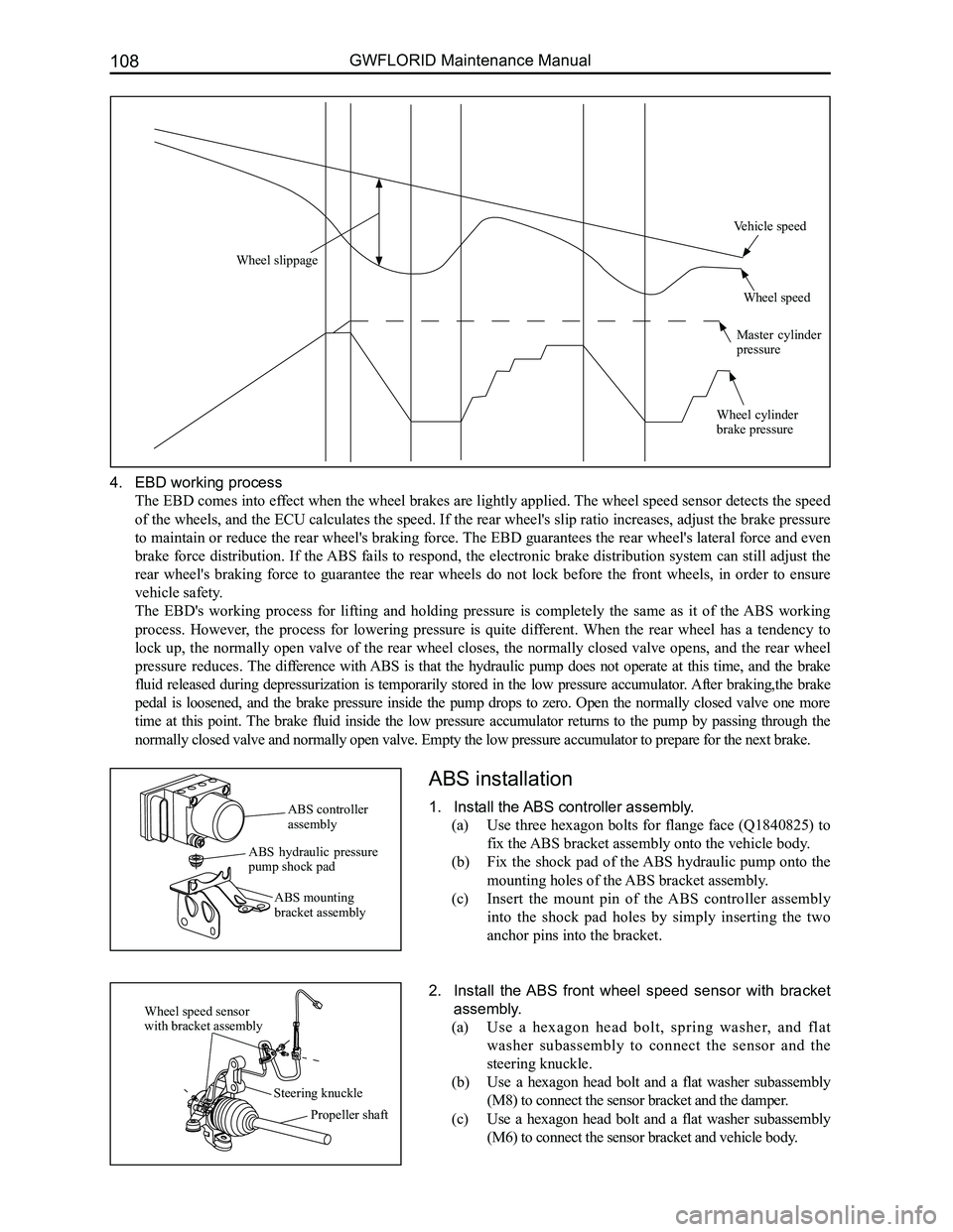
4. EBD working process
The EBD comes into effect when the wheel brakes are lightly applied. The wheel speed sensor detects the speed
of the wheels, and the ECU calculates the speed. If the rear wheel's slip ratio increases, adjust the brake pressure
to maintain or reduce the rear wheel's braking force. The EBD guarantees the rear wheel's lateral force and even
brake force distribution. If the ABS fails to respond, the electronic brake distribution system can still adjust the
rear wheel's braking force to guarantee the rear wheels do not lock before the front wheels, in order to ensure
vehicle safety.
The EBD's working process for lifting and holding pressure is completely the same as it of the ABS working
process. However, the process for lowering pressure is quite different. When the rear wheel has a tendency to
lock up, the normally open valve of the rear wheel closes, the normally closed valve opens, and the rear wheel
pressure reduces. The difference with ABS is that the hydraulic pump does not operate at this time, and the brake
fluid released during depressurization is temporarily stored in the low pressure accumulator. After braking,the brake
pedal is loosened, and the brake pressure inside the pump drops to zero. Open the normally closed valve one more
time at this point. The brake fluid inside the low pressure accumulator returns to the pump by passing through the
normally closed valve and normally open valve. Empty the low pressure ac\
cumulator to prepare for the next brake.
ABS installation
1. Install the ABS controller assembly.
(a) Use three hexagon bolts for flange face (Q1840825) to
fix the ABS bracket assembly onto the vehicle body.
(b) Fix the shock pad of the ABS hydraulic pump onto the
mounting holes of the ABS bracket assembly.
(c) Insert the mount pin of the ABS controller assembly
into the shock pad holes by simply inserting the two
anchor pins into the bracket.
2. Install the ABS front wheel speed sensor with bracket
assembly.
(a) Use a hexagon head bolt, spring washer, and flat
washer subassembly to connect the sensor and the
steering knuckle.
(b) Use a hexagon head bolt and a flat washer subassembly
(M8) to connect the sensor bracket and the damper.
(c) Use a hexagon head bolt and a flat washer subassembly
(M6) to connect the sensor bracket and vehicle body.
ABS controller assembly
ABS hydraulic pressure pump shock pad
ABS mounting bracket assembly
Wheel speed sensor with bracket assembly
Steering knuckle
Propeller shaft
Wheel slippage
Vehicle speed
Wheel speed
Master cylinder pressure
Wheel cylinder brake pressure
Page 117 of 281
Downloaded from www.Manualslib.com manuals search engine GWFLORID Maintenance Manual110
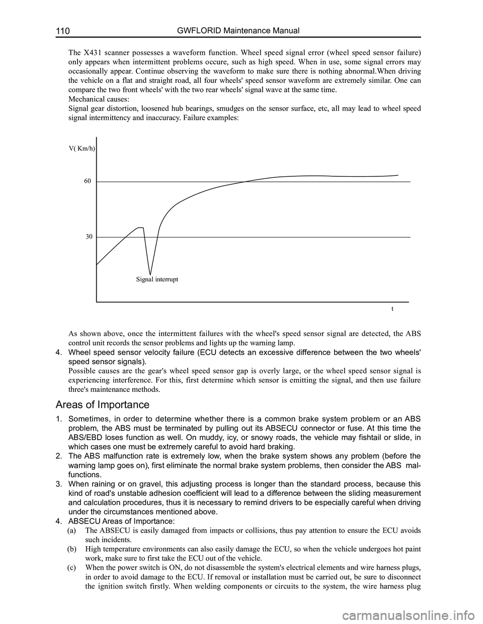
The X431 scanner possesses a waveform function. Wheel speed signal error (wheel speed sensor failure)
only appears when intermittent problems occure, such as high speed. When in use, some signal errors may
occasionally appear. Continue observing the waveform to make sure there is nothing abnormal.When driving
the vehicle on a flat and straight road, all four wheels' speed sensor waveform are extremely similar. One can
compare the two front wheels' with the two rear wheels' signal wave at t\
he same time.
Mechanical causes:
Signal gear distortion, loosened hub bearings, smudges on the sensor surface, etc, all may lead to wheel speed
signal intermittency and inaccuracy. Failure examples:
As shown above, once the intermittent failures with the wheel's speed sensor signal are detected, the ABS
control unit records the sensor problems and lights up the warning lamp.\
4. Wheel speed sensor velocity failure (ECU detects an excessive difference between the two wheels'
speed sensor signals).
Possible causes are the gear's wheel speed sensor gap is overly large, or the wheel speed sensor signal is
experiencing interference. For this, first determine which sensor is emitting the signal, and then use failure
three's maintenance methods.
Areas of Importance
1. Sometimes, in order to determine whether there is a common brake system problem or an ABS
problem, the ABS must be terminated by pulling out its ABSECU connector or fuse. At this time the
ABS/EBD loses function as well. On muddy, icy, or snowy roads, the vehicle may fishtail or slide, in
which cases one must be extremely careful to avoid hard braking.
2. The ABS malfunction rate is extremely low, when the brake system shows any problem (before the
warning lamp goes on), first eliminate the normal brake system problems, then consider the ABS mal-
functions.
3. When raining or on gravel, this adjusting process is longer than the standard process, because this
kind of road's unstable adhesion coefficient will lead to a difference between the sliding measurement
and calculation procedures, thus it is necessary to remind drivers to be especially careful when driving
under the circumstances mentioned above.
4. ABSECU Areas of Importance:
(a) The ABSECU is easily damaged from impacts or collisions, thus pay attention to ensure the ECU avoids
such incidents.
(b) High temperature environments can also easily damage the ECU, so when the vehicle undergoes hot paint
work, make sure to first take the ECU out of the vehicle.
(c) When the power switch is ON, do not disassemble the system's electrical elements and wire harness plugs,
in order to avoid damage to the ECU. If removal or installation must be carried out, be sure to disconnect
the ignition switch firstly. When welding components or circuits to the system, the wire harness plug
V( Km/h)
60
30
Signal interrupt
t
Page 118 of 281
Downloaded from www.Manualslib.com manuals search engine 111Brake System
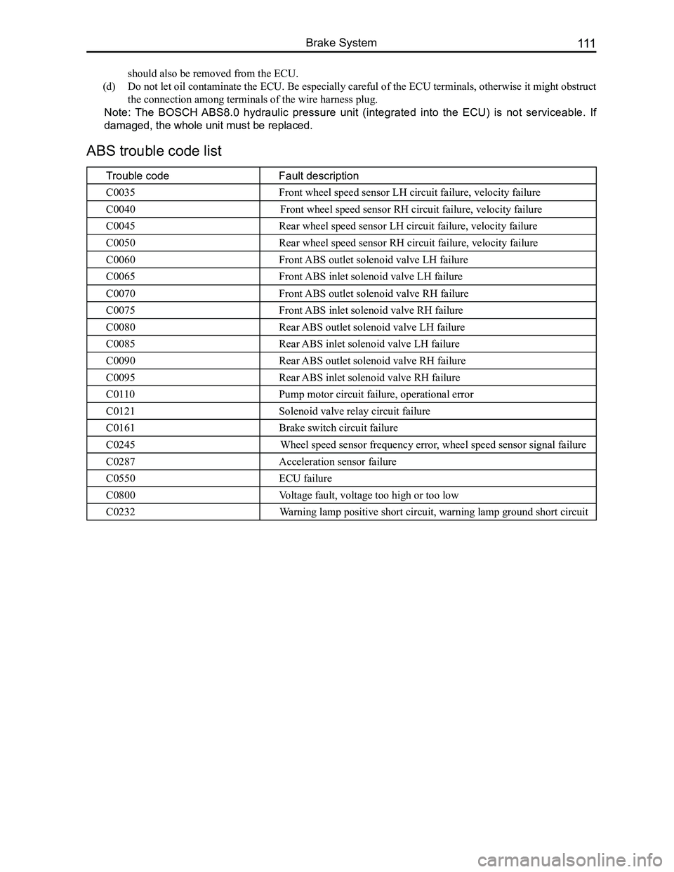
ABS trouble code list
Trouble codeFault description
C0035Front wheel speed sensor LH circuit failure, velocity failure
C0040Front wheel speed sensor RH circuit failure, velocity failure
C0045Rear wheel speed sensor LH circuit failure, velocity failure
C0050Rear wheel speed sensor RH circuit failure, velocity failure
C0060Front ABS outlet solenoid valve LH failure
C0065Front ABS inlet solenoid valve LH failure
C0070Front ABS outlet solenoid valve RH failure
C0075Front ABS inlet solenoid valve RH failure
C0080Rear ABS outlet solenoid valve LH failure
C0085Rear ABS inlet solenoid valve LH failure
C0090Rear ABS outlet solenoid valve RH failure
C0095Rear ABS inlet solenoid valve RH failure
C0110Pump motor circuit failure, operational error
C0121Solenoid valve relay circuit failure
C0161Brake switch circuit failure
C0245Wheel speed sensor frequency error, wheel speed sensor signal failure
C0287Acceleration sensor failure
C0550ECU failure
C0800Voltage fault, voltage too high or too low
C0232Warning lamp positive short circuit, warning lamp ground short circuit
should also be removed from the ECU.
(d) Do not let oil contaminate the ECU. Be especially careful of the ECU terminals, otherwise it might obstruct
the connection among terminals of the wire harness plug.
Note: The BOSCH ABS8.0 hydraulic pressure unit (integrated into the ECU) is not serviceable. If
damaged, the whole unit must be replaced.
Page 120 of 281
Downloaded from www.Manualslib.com manuals search engine 113Brake System
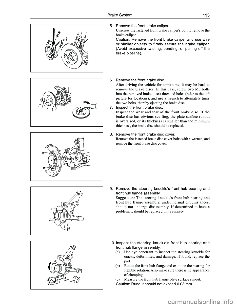
5. Remove the front brake caliper.
Unscrew the fastened front brake caliper's bolt to remove the
brake caliper.
Caution: Remove the front brake caliper and use wire
or similar objects to firmly secure the brake caliper.
(Avoid excessive twisting, bending, or pulling off the
brake pipeline).
6. Remove the front brake disc.
After driving the vehicle for some time, it may be hard to
remove the brake discs. In this case, screw two M8 bolts
into the removed brake disc's threaded holes (refer to the left
picture for locations), and use a wrench to alternately turns
the two bolts, thereby ejecting the brake disc.
7. Inspect the front brake disc.
Inspect the wear and tear of the front brake disc. If the
brake disc has obvious scuffing, the plate surface runout
is oversized, or its thickness is smaller than the minimum
thickness, the brake disc should be replaced.
8. Remove the front brake disc cover.
Remove the fastened brake disc cover bolts with a wrench, and
remove the front brake disc cover.
9. Remove the steering knuckle's front hub bearing and
front hub flange assembly.
Suggestion: The steering knuckle's front hub bearing and
front hub flange assembly, under normal circumstances,
should not undergo disassembly. If determined to have a
problem, it should be replaced in its entirety.
10. Inspect the steering knuckle's front hub bearing and
front hub flange assembly.
(a) Use dye penetrant to inspect the steering knuckle for
cracks, deformities, and damage. If found, replace the
part.
(b) Rotate the front hub flange and examine the bearing for
flexible rotation. Also make sure there is no appearance
of clamping.
(c) Measure the front hub flange plate surface runout.
Caution: Runout should not exceed 0.03 mm.
Page 148 of 281
Downloaded from www.Manualslib.com manuals search engine 141Steering System
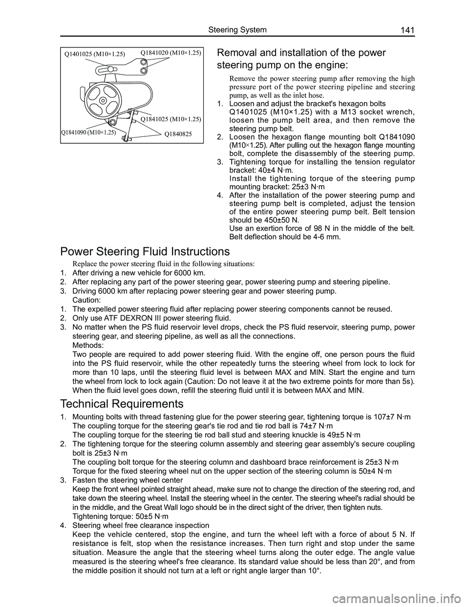
Removal and installation of the power
steering pump on the engine:
Remove the power steering pump after removing the high
pressure port of the power steering pipeline and steering
pump, as well as the inlet hose.
1. Loosen and adjust the bracket's hexagon bolts
Q1401025 (M10×1.25) with a M13 socket wrench,
l o o s e n t h e p u m p b e l t a r e a , a n d t h e n r e m o v e t h e
steering pump belt.
2. Loosen the hexagon flange mounting bolt Q1841090
(M10×1.25). After pulling out the hexagon flange mounting
bolt, complete the disassembly of the steering pump.
3. Tightening torque for installing the tension regulator
bracket: 40±4 N·m.
Install the tightening torque of the steering pump
mounting bracket: 25±3 N·m
4. After the installation of the power steering pump and
steering pump belt is completed, adjust the tension
of the entire power steering pump belt. Belt tension
should be 450±50 N.
Use an exertion force of 98 N in the middle of the belt.
Belt deflection should be 4-6 mm.
Power Steering Fluid Instructions
Replace the power steering fluid in the following situations:
1. After driving a new vehicle for 6000 km.
2. After replacing any part of the power steering gear, power steering pump and steering pipeline.
3. Driving 6000 km after replacing power steering gear and power steering p\
ump.
Caution:
1. The expelled power steering fluid after replacing power steering compone\
nts cannot be reused.
2. Only use ATF DEXRON III power steering fluid.
3. No matter when the PS fluid reservoir level drops, check the PS fluid reservoir, steering pump, power
steering gear, and steering pipeline, as well as all the connections.
Methods:
Two people are required to add power steering fluid. With the engine off, one person pours the fluid
into the PS fluid reservoir, while the other repeatedly turns the steering wheel from lock to lock for
more than 10 laps, until the steering fluid level is between MAX and MIN. Start the engine and turn
the wheel from lock to lock again (Caution: Do not leave it at the two extreme points for more than 5s).
When the fluid level goes down, refill the steering fluid until it is be\
tween MAX and MIN.
Technical Requirements
1. Mounting bolts with thread fastening glue for the power steering gear, tightening torque is 107±7 N·m
The coupling torque for the steering gear's tie rod and tie rod ball is \
74±7 N·m
The coupling torque for the steering tie rod ball stud and steering knuc\
kle is 49±5 N·m
2. The tightening torque for the steering column assembly and steering gear assembly's secure coupling
bolt is 25±3 N·m
The coupling bolt torque for the steering column and dashboard brace rei\
nforcement is 25±3 N·m
Torque for the fixed steering wheel nut on the upper section of the steer\
ing column is 50±4 N·m
3. Fasten the steering wheel center
Keep the front wheel pointed straight ahead, make sure not to change the direction of the steering rod, and
take down the steering wheel. Install the steering wheel in the center. The steering wheel's radial should be
in the middle, and the Great Wall logo should be in the direct sight of the driver, then tighten nuts.
Tightening torque: 50±5 N·m
4. Steering wheel free clearance inspection
Keep the vehicle centered, stop the engine, and turn the wheel left with a force of about 5 N. If
resistance is felt, stop when the resistance increases. Then turn right and stop under the same
situation. Measure the angle that the steering wheel turns along the outer edge. The angle value
measured is the steering wheel's free clearance. Its standard value should be less than 20°, and from
the middle position it should not turn at a left or right angle larger t\
han 10°.
Q1401025 (M10×1.25)Q1841020 (M10×1.25)
Q1841025 (M10×1.25)
Q1840825Q1841090 (M10×1.25)
Page 151 of 281
Downloaded from www.Manualslib.com manuals search engine GWFLORID Maintenance Manual144
Double-colored wire: Primary color is Red, secondary color is Blue, mark\
ed as RBl.
0.5BrGr means Brown wire with a Gray fine wire, and sectional area is 0.\
5 mm2.
Areas of importance in circuit maintenance
1. Before operating any electronic devices, and when tools or maintenance devices may easily make
contact with an uncovered electronic terminal, please make sure to turn the ignition switch to the LOCK
position, and then disconnect the battery's negative cable to avoid injury or vehicle damage. When the
ignition switch is on the ON position, please do not disconnect the battery's connecting wire or take out
the power's fuse, regardless if the engine is running or not.Otherwise it would seriously damage the
ECU and related microelectronic devices such as sensors.
2. When changing the fuse, please make sure that the new fuse possesses the proper current rating,
and is not above or below this rating.
3. When repairing the wire harnesses of the airbag and pretensioner, only specified contact points,
plugs, and wires are allowed to be used.
4. Before repairing the wire harness, make sure to eliminate any factor that might cause damage,
for example, the edge of a vehicle body part is too sharp, or the used electronics are damaged or
corroded.
5. Shielded wire should not be repaired, it must be replaced entirely once it is damaged.
6. Unless it is specified during the test, please do not use an analog multimeter to test the ECU and
sensor, instead use a high-impedance digital multimeter (internal resistance should be ≥10 kΩ) or a
vehicle multimeter for inspection.
7. When inspecting the connector with a digital multimeter, take the waterproof rubber cover off the
connector, and tightly insert the test pen along the connecting terminal. Don't use too much force, as
to avoid cracking the connector.
Circuit inspection steps
The principle of troubleshooting is to confirm the "possible cause". Once the possible cause is confirmed, the
components that need to be inspected are limited to the components that are related to the possible cause. The
confirmed possible cause should be based on theory and be supported by facts, but not just by intuition. If
one tries to solve the problem but does not adopt the proper troubleshooting steps, it may make the problem
worse. Then the possible cause not only can't be confirmed, but also maintenance can't be performed properly.
Troubleshooting should adhere to the four steps below:
1. Observe the symptoms carefully, inspect if there is anything else abnormal, and record it.
2. While confirming the possible causes, study the circuit diagram carefully, and regard it as a whole
system in order to understand the circuit. Thorough knowledge of switches, relays, and other
electronic components is obligatory for proper analysis.
3. Inspect and eliminate the problems one by one until the cause is found.
4. After the malfunction is fixed, make sure to check if the inspected system is working properly, and also
check if the maintenance may have caused any new problems.
Compres-
sor relay
Reserve
Sunroof (Elite) Lamplet
Reserve
Reserve
Reserve
Reserve Door and window Reserve Blower
Lamplet
relay Flasher relay Blower high
speed relay (Elite) Door and
window relay (Comfort, Luxury) Blower relay
Reserve
Front fog lamp
Combination
meter
Interior
lighting
central
door lock
brake lamp
CD player
Reserve
Reserve
Reserve
Cigarette
lighter
Rearview
mirror
Front wiper
Charge
Airbag
Reserve
Reverse lamp Rear fog lamp
Rear wiper
Defroster Compressor
ACC relay
IG relayRear wiper
relay Defroster
relay
Front fog
lamp relay Rear fog
lamp relay
Warning lamp
Turn signal lamp
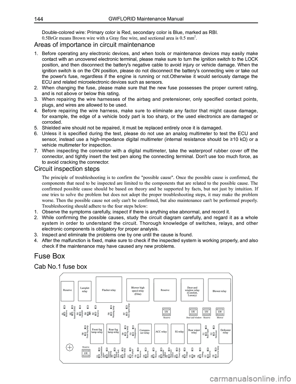
Cab No.1 fuse box
Fuse Box