2008 GREAT WALL FLORID dashboard
[x] Cancel search: dashboardPage 7 of 281

Downloaded from www.Manualslib.com manuals search engine Airbag’s Diagnostic Methods Without a Diagnostic Scanner ...................................232
Chapter Thirteen: Vehicle Body ........................................................................\
........................233
Front Door Lock Assembly ...................................................................................\
....234
Rear Door Lock Assembly ..................................................................................\
.....237
Trunk Door Lock Assembly ...................................................................................\
...239
Wiper Arm and Vent Panel Assembly ......................................................................240
Front & Rear Window Glasses ................................................................................241
Dashboard ..................................................................................\
.............................242
Cooling Unit ..................................................................................\
...........................246
Front Door Assembly ..................................................................................\
.............248
Rear Door Assembly ...................................................................................\
.............251
Trunk Door Assembly ...................................................................................\
............254
Front Bumper ...................................................................................\
........................256
Rear Bumper ..................................................................................\
.........................259
Seat Belt ..................................................................................\
................................262
Seats ...................................................................................\
.....................................266
Sunroof Assembly ...................................................................................\
.................268
Page 22 of 281

Downloaded from www.Manualslib.com manuals search engine 15Overall Parameters
Vehicle Structure Type and Parameters
ItemStructural parameters & performance descriptions
Body
Body typeAll-metal closed hard surface bearing body.
Body in whitePressed and welded, all-metal enclosed structure.
Door assemblyFramed door with four-door impact beam, hinged sliding open door, trunk door
opens upwards, front/rear doors are installed with auto window regulator\
.
Engine hoodOpens up/downwards using a single arm hinge.
Closure part
parameters
Front door opening
angle35°/60°Engine hood
opening angle74.5°
Rear door opening
angle36°/64°Trunk door max.
opening angle96°
Vehicle
interior/
exterior and
accessories
Interior Satisfies ergonomic and comfort requirements. Fire resistance complies to regulatory
requirements.
Dashboard
Uses an injected molding structure with brace reinforcement, built in multifunctional
combination meter, knob plus button-press air conditioning controller, CD player
(DVD and GPS LCD are optional), and auxiliary facia console which adopts a gear
shift control mechanism.
A, B, C, and D
pillars and door's
inner decoration
board
Uses injected molding and front door guard plates equipped with package tray, four-
door guard plates are all installed with window regulator switches.
Automobile
glass
Windshield is laminated glass, front and rear door glass is tempered glass, trunk door
glass is heating & defrosting tempered glass with resistance wire.
Outer rearview
mirror
Elite type: electrically actuated convertible body and electronically controlled mirror
with defroster.
Luxury type: manually folded body and electronically controlled mirror without
defroster.
Comfort type: manually folded body and manually adjusted mirror without \
defroster.
Inner rearview
mirrorFlexible with anti-glare function
Seats
Driver & front passenger seats, independent seats. For front and rear seats, backrest
angle and seat headrest are both manually adjustable. Second row seats use a three-
seat arrangement. The seats' front and back positions and backrest angles are
nonadjustable. Seat headrests are both manually adjustable, back of the seat can be
folded forward, and the middle seat includes a child seat belt.
Seat belt
The front seat has two kinds of seat belts, complex equipment type being an
electronic preload three-point seat belt, and simple equipment type a non-preload
three-point seat belt. Advanced configuration uses the electronic preload three-point
seat belt, while simple configuration uses the non-preloaded three-point seat belt.
The rear seat belt uses a normal three-point seat belt.
Sun visor
Left and right sun visors both have cosmetic mirrors, and the sun visors can be
rotated up and down and from side to side, the up and down rotation can be held at
any position.
Front and rear
bumperBumper assembly can withstand collision speeds of 8 km/h.
Washer
Equipped with front and rear wiper, one 5th gear thrust washer reservoir, two motors,
two sets of pipelines in the front and rear, two washing nozzles with one in the front,
and the other in the back.
Page 24 of 281

Downloaded from www.Manualslib.com manuals search engine 17Overall Parameters
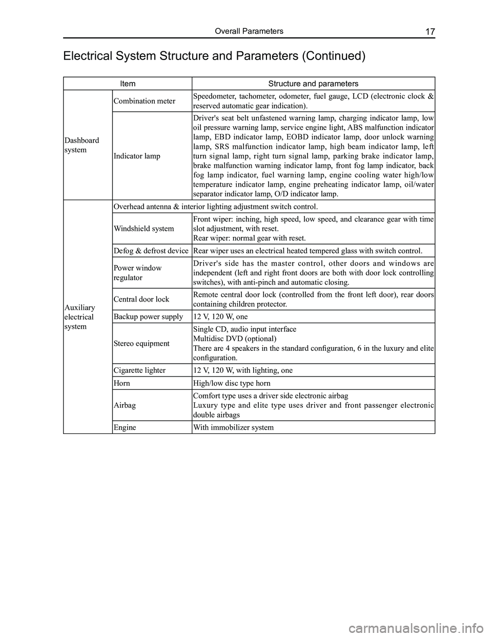
ItemStructure and parameters
Dashboard
system
Combination meter Speedometer, tachometer, odometer, fuel gauge, LCD (electronic clock &
reserved automatic gear indication).
Indicator lamp
Driver's seat belt unfastened warning lamp, charging indicator lamp, low
oil pressure warning lamp, service engine light, ABS malfunction indicator
lamp, EBD indicator lamp, EOBD indicator lamp, door unlock warning
lamp, SRS malfunction indicator lamp, high beam indicator lamp, left
turn signal lamp, right turn signal lamp, parking brake indicator lamp,
brake malfunction warning indicator lamp, front fog lamp indicator, back
fog lamp indicator, fuel warning lamp, engine cooling water high/low
temperature indicator lamp, engine preheating indicator lamp, oil/water
separator indicator lamp, O/D indicator lamp.
Auxiliary
electrical
system
Overhead antenna & interior lighting adjustment switch control.
Windshield system
Front wiper: inching, high speed, low speed, and clearance gear with time
slot adjustment, with reset.
Rear wiper: normal gear with reset.
Defog & defrost deviceRear wiper uses an electrical heated tempered glass with switch control.\
Power window
regulator
D r i v e r ' s s i d e h a s t h e m a s t e r c o n t r o l , o t h e r d o o r s a n d w i n d o w s a r e
independent (left and right front doors are both with door lock controlling
switches), with anti-pinch and automatic closing.
Central door lockRemote central door lock (controlled from the front left door), rear doors
containing children protector.
Backup power supply12 V, 120 W, one
Stereo equipment
Single CD, audio input interface
Multidisc DVD (optional)
There are 4 speakers in the standard configuration, 6 in the luxury and elite
configuration.
Cigarette lighter12 V, 120 W, with lighting, one
HornHigh/low disc type horn
Airbag
Comfort type uses a driver side electronic airbag
Luxury type and elite type uses driver and front passenger electronic
double airbags
EngineWith immobilizer system
Electrical System Structure and Parameters (Continued)
Page 47 of 281

Downloaded from www.Manualslib.com manuals search engine GWFLORID Maintenance Manual40
Clutch Master Cylinder Installation
Installation of clutch system is reverse to its removal, but
since the whole clutch system uses hydraulic assistance,
make sure to air bleed it after the installation is completed.
Detailed steps as follows:
(a) Plug one end of the long transparent connection hose
(about 0.5 m long) into the bottom of bleed screw, and
the other end into a fixed container.
(b) Loosen the bleed screw via the open end of the M8,
meanwhile ask the assistant to step on the clutch pedal
repeatedly until no air bubbles can be seen in the hose.
R e m a r k : R e s i d u a l a i r i n t h e c l u t c h s y s t e m h a s b e e n
completely exhausted.
(c) Lastly, lock the bleed screw.
Caution: Refilling the brake fluid reservoir should be
performed while air bleeding the clutch.
Clutch Pedal Removal
1. Remove the battery's negative cable.
2. Remove the glove box at the left of the dashboard.
3. Remove the cotter pin at the U-joint of the clutch
master cylinder, and separate the center pin and the
pedal lever.
4. Remove the clutch pedal bracket from the cowl.
5. Remove the clutch pedal.
(a) Move the clutch pedal to the maximum stroke position.
(b) Take down the return spring.
(c) Remove the bolts and nuts.
(d) Take the pedal lever down from the pedal bracket.
Clutch Pedal Installation
1. Install the clutch pedal.
(a) Install the return spring.
(b) Install the clutch pedal lever.
(c) Install the bolts and nuts.
Tightening torque: 30 N·m
(d) Put the pedal lever at the maximum stroke position and
connect it with the spring, in order to set the pedal to its
initial position.
2. Install the clutch pedal onto the 2 studs of the clutch
master cylinder.
Use a M13 wrench to tighten the clutch pedal brackets with
two M8 nuts.
Tightening torque: 23±3 N·m
3. Install the clutch master cylinder push rod with the U-
joint.
(a) Coat the contact areas between the center pin and the
U-joint pedal connector with multi-functional grease.
(b) In succession, join the U-joint (pedal connector) and
the clutch pedal lever with a cotter pin.
Caution: Insert the center pin into the pedal lever from
the left side of vehicle.
(c) Install the cotter pin onto the center pin.
4. Check and adjust the clutch pedal.
5. Connect the negative cable of the battery.
Bleed screw
Page 148 of 281

Downloaded from www.Manualslib.com manuals search engine 141Steering System
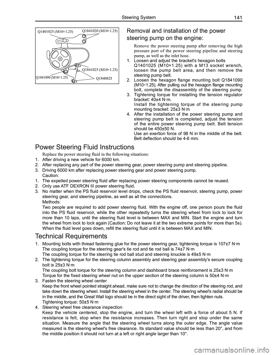
Removal and installation of the power
steering pump on the engine:
Remove the power steering pump after removing the high
pressure port of the power steering pipeline and steering
pump, as well as the inlet hose.
1. Loosen and adjust the bracket's hexagon bolts
Q1401025 (M10×1.25) with a M13 socket wrench,
l o o s e n t h e p u m p b e l t a r e a , a n d t h e n r e m o v e t h e
steering pump belt.
2. Loosen the hexagon flange mounting bolt Q1841090
(M10×1.25). After pulling out the hexagon flange mounting
bolt, complete the disassembly of the steering pump.
3. Tightening torque for installing the tension regulator
bracket: 40±4 N·m.
Install the tightening torque of the steering pump
mounting bracket: 25±3 N·m
4. After the installation of the power steering pump and
steering pump belt is completed, adjust the tension
of the entire power steering pump belt. Belt tension
should be 450±50 N.
Use an exertion force of 98 N in the middle of the belt.
Belt deflection should be 4-6 mm.
Power Steering Fluid Instructions
Replace the power steering fluid in the following situations:
1. After driving a new vehicle for 6000 km.
2. After replacing any part of the power steering gear, power steering pump and steering pipeline.
3. Driving 6000 km after replacing power steering gear and power steering p\
ump.
Caution:
1. The expelled power steering fluid after replacing power steering compone\
nts cannot be reused.
2. Only use ATF DEXRON III power steering fluid.
3. No matter when the PS fluid reservoir level drops, check the PS fluid reservoir, steering pump, power
steering gear, and steering pipeline, as well as all the connections.
Methods:
Two people are required to add power steering fluid. With the engine off, one person pours the fluid
into the PS fluid reservoir, while the other repeatedly turns the steering wheel from lock to lock for
more than 10 laps, until the steering fluid level is between MAX and MIN. Start the engine and turn
the wheel from lock to lock again (Caution: Do not leave it at the two extreme points for more than 5s).
When the fluid level goes down, refill the steering fluid until it is be\
tween MAX and MIN.
Technical Requirements
1. Mounting bolts with thread fastening glue for the power steering gear, tightening torque is 107±7 N·m
The coupling torque for the steering gear's tie rod and tie rod ball is \
74±7 N·m
The coupling torque for the steering tie rod ball stud and steering knuc\
kle is 49±5 N·m
2. The tightening torque for the steering column assembly and steering gear assembly's secure coupling
bolt is 25±3 N·m
The coupling bolt torque for the steering column and dashboard brace rei\
nforcement is 25±3 N·m
Torque for the fixed steering wheel nut on the upper section of the steer\
ing column is 50±4 N·m
3. Fasten the steering wheel center
Keep the front wheel pointed straight ahead, make sure not to change the direction of the steering rod, and
take down the steering wheel. Install the steering wheel in the center. The steering wheel's radial should be
in the middle, and the Great Wall logo should be in the direct sight of the driver, then tighten nuts.
Tightening torque: 50±5 N·m
4. Steering wheel free clearance inspection
Keep the vehicle centered, stop the engine, and turn the wheel left with a force of about 5 N. If
resistance is felt, stop when the resistance increases. Then turn right and stop under the same
situation. Measure the angle that the steering wheel turns along the outer edge. The angle value
measured is the steering wheel's free clearance. Its standard value should be less than 20°, and from
the middle position it should not turn at a left or right angle larger t\
han 10°.
Q1401025 (M10×1.25)Q1841020 (M10×1.25)
Q1841025 (M10×1.25)
Q1840825Q1841090 (M10×1.25)
Page 150 of 281

Downloaded from www.Manualslib.com manuals search engine 143Vehicle Body Electronic System
Basic Information on the Electrical System
Electrical system schematics reading instructions
1. Configuration introduction
The GWFLORID comes in three configurations: comfort, luxury and elite. The wire harness has two types of
configurations: One is a non jam protection comfort model, which is a combination of both comfort and luxury
type, the other type is called elite. These two configurations are universally used in most of this manual. The
parts that are only available for the non jam protection comfort type have been marked in this manual, please
pay attention to these sections while performing maintenance.
2. Fuse box and power supply introduction
The fuse box located inside the left side of the dashboard is No. 1 Fuse Box, the other one inside the left side of
the engine compartment is No. 2 Fuse Box.
• 30 represents a power cord for normal power, which is from the battery positive fuse box-60 A.
• 30a represents a power cord for normal power, which is from the battery positive fuse box-120 A.
• 30b represents a power cord for normal power, which is from the battery positive fuse box-120 A.
• 15 represents a power cord for small capacity electronics. When the ignition switch is at the "ON" position,
power is supplied by relay IG.
• 15a represents a power cord for small capacity electronics. When the ignition switch is at the "ON"
position, power is directly supplied by ignition switch IG1.
• 15b represents a power cord for small capacity electronics. When the ignition switch is at the "ON"
position, power is directly supplied by ignition switch IG2.
• X represents a power cord for small capacity electronics. When the ignition switch is at the "ACC"
position, power is supplied by relay ACC.
4. Wire's color and sectional area (mm2)
B-BlackW-WhiteR-RedBl-BlueBr-BrownY-Yellow
G-GreenP-PinkOr-OrangeV-VioletLg-Light greenGr-Gray
Mark the solid-colored wires with the letters in the above table. Double-colored wires' first letter is the primary
color, second letter is the secondary color.
For example:
Solid-colored wire: Red, marked as R.
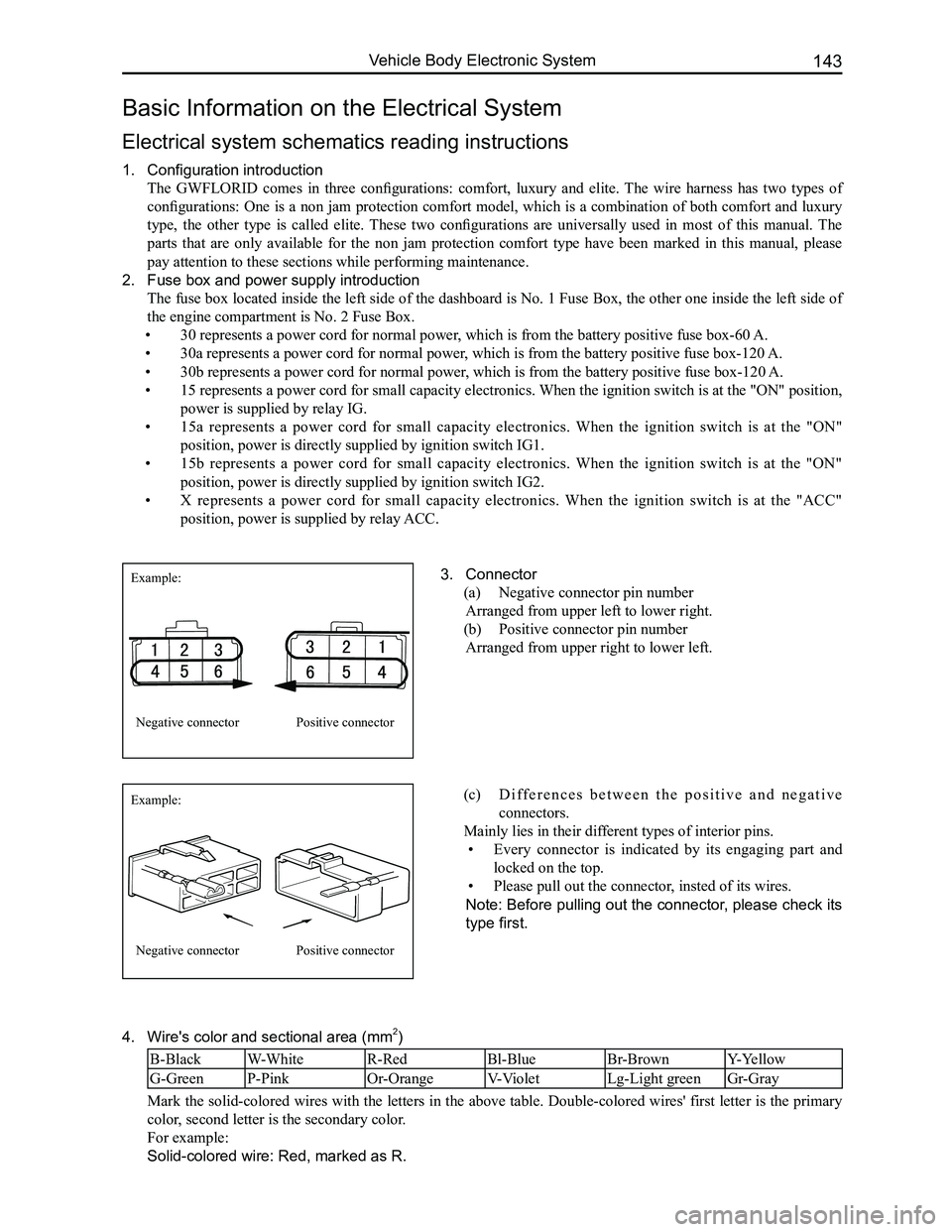
3. Connector
(a) Negative connector pin number
Arranged from upper left to lower right.
(b) Positive connector pin number
Arranged from upper right to lower left.
Example:
Example:
Negative connector
Negative connector
Positive connector
Positive connector
(c) D i f f e r e n c e s b e t w e e n t h e p o s i t i v e a n d n e g a t i v e
connectors.
Mainly lies in their different types of interior pins.
• Every connector is indicated by its engaging part and
locked on the top.
• Please pull out the connector, insted of its wires.
Note: Before pulling out the connector, please check its
type first.
Page 154 of 281

Downloaded from www.Manualslib.com manuals search engine 147Vehicle Body Electronic System
Eilte
Cab No.1 fuse box back side pin diagram
Connected dashboard's
wire harness A
Connected dashboard's
wire harness B
Connected dashboard's
wire harness C
Connected dashboard's
wire harness D
Connected dashboard's
wire harness EConnected dashboard's
wire harness H
A
BC
D
EF
H
(Elite)
Page 158 of 281

Downloaded from www.Manualslib.com manuals search engine 151Vehicle Body Electronic System
G09
NumberGrounding positionRemark
G01, G02Inside the engine compartment's
left side fenderEngine compartment's wire harness
G03Inside the engine compartment's
right side fenderEngine compartment's wire harness
G04, G05Wire harness fixture un-
der the right A-pillarEngine & dashboard wire harness
G06Wire harness fixture un-
der the left A-pillarMeter wire harness
G06 On the dashboard brace reinforcementMeter wire harness
G07Rear fender trim LHVehicle body wire harness
G08Near rear combination lamp RHVehicle body wire harness
G09Near rear wiper motorTrunk door wire harness assembly
G10Airbag grounding point
Meaning of each number representation:
Key Electrical Component’s Module Schematics for the Overall
Vehicle
Theft deterrent ECUCentral lock controller
No.1 fuse box
Airbag ECU assembly
Engine ECU
G10