2008 GREAT WALL FLORID rear view mirror
[x] Cancel search: rear view mirrorPage 22 of 281

Downloaded from www.Manualslib.com manuals search engine 15Overall Parameters
Vehicle Structure Type and Parameters
ItemStructural parameters & performance descriptions
Body
Body typeAll-metal closed hard surface bearing body.
Body in whitePressed and welded, all-metal enclosed structure.
Door assemblyFramed door with four-door impact beam, hinged sliding open door, trunk door
opens upwards, front/rear doors are installed with auto window regulator\
.
Engine hoodOpens up/downwards using a single arm hinge.
Closure part
parameters
Front door opening
angle35°/60°Engine hood
opening angle74.5°
Rear door opening
angle36°/64°Trunk door max.
opening angle96°
Vehicle
interior/
exterior and
accessories
Interior Satisfies ergonomic and comfort requirements. Fire resistance complies to regulatory
requirements.
Dashboard
Uses an injected molding structure with brace reinforcement, built in multifunctional
combination meter, knob plus button-press air conditioning controller, CD player
(DVD and GPS LCD are optional), and auxiliary facia console which adopts a gear
shift control mechanism.
A, B, C, and D
pillars and door's
inner decoration
board
Uses injected molding and front door guard plates equipped with package tray, four-
door guard plates are all installed with window regulator switches.
Automobile
glass
Windshield is laminated glass, front and rear door glass is tempered glass, trunk door
glass is heating & defrosting tempered glass with resistance wire.
Outer rearview
mirror
Elite type: electrically actuated convertible body and electronically controlled mirror
with defroster.
Luxury type: manually folded body and electronically controlled mirror without
defroster.
Comfort type: manually folded body and manually adjusted mirror without \
defroster.
Inner rearview
mirrorFlexible with anti-glare function
Seats
Driver & front passenger seats, independent seats. For front and rear seats, backrest
angle and seat headrest are both manually adjustable. Second row seats use a three-
seat arrangement. The seats' front and back positions and backrest angles are
nonadjustable. Seat headrests are both manually adjustable, back of the seat can be
folded forward, and the middle seat includes a child seat belt.
Seat belt
The front seat has two kinds of seat belts, complex equipment type being an
electronic preload three-point seat belt, and simple equipment type a non-preload
three-point seat belt. Advanced configuration uses the electronic preload three-point
seat belt, while simple configuration uses the non-preloaded three-point seat belt.
The rear seat belt uses a normal three-point seat belt.
Sun visor
Left and right sun visors both have cosmetic mirrors, and the sun visors can be
rotated up and down and from side to side, the up and down rotation can be held at
any position.
Front and rear
bumperBumper assembly can withstand collision speeds of 8 km/h.
Washer
Equipped with front and rear wiper, one 5th gear thrust washer reservoir, two motors,
two sets of pipelines in the front and rear, two washing nozzles with one in the front,
and the other in the back.
Page 151 of 281

Downloaded from www.Manualslib.com manuals search engine GWFLORID Maintenance Manual144
Double-colored wire: Primary color is Red, secondary color is Blue, mark\
ed as RBl.
0.5BrGr means Brown wire with a Gray fine wire, and sectional area is 0.\
5 mm2.
Areas of importance in circuit maintenance
1. Before operating any electronic devices, and when tools or maintenance devices may easily make
contact with an uncovered electronic terminal, please make sure to turn the ignition switch to the LOCK
position, and then disconnect the battery's negative cable to avoid injury or vehicle damage. When the
ignition switch is on the ON position, please do not disconnect the battery's connecting wire or take out
the power's fuse, regardless if the engine is running or not.Otherwise it would seriously damage the
ECU and related microelectronic devices such as sensors.
2. When changing the fuse, please make sure that the new fuse possesses the proper current rating,
and is not above or below this rating.
3. When repairing the wire harnesses of the airbag and pretensioner, only specified contact points,
plugs, and wires are allowed to be used.
4. Before repairing the wire harness, make sure to eliminate any factor that might cause damage,
for example, the edge of a vehicle body part is too sharp, or the used electronics are damaged or
corroded.
5. Shielded wire should not be repaired, it must be replaced entirely once it is damaged.
6. Unless it is specified during the test, please do not use an analog multimeter to test the ECU and
sensor, instead use a high-impedance digital multimeter (internal resistance should be ≥10 kΩ) or a
vehicle multimeter for inspection.
7. When inspecting the connector with a digital multimeter, take the waterproof rubber cover off the
connector, and tightly insert the test pen along the connecting terminal. Don't use too much force, as
to avoid cracking the connector.
Circuit inspection steps
The principle of troubleshooting is to confirm the "possible cause". Once the possible cause is confirmed, the
components that need to be inspected are limited to the components that are related to the possible cause. The
confirmed possible cause should be based on theory and be supported by facts, but not just by intuition. If
one tries to solve the problem but does not adopt the proper troubleshooting steps, it may make the problem
worse. Then the possible cause not only can't be confirmed, but also maintenance can't be performed properly.
Troubleshooting should adhere to the four steps below:
1. Observe the symptoms carefully, inspect if there is anything else abnormal, and record it.
2. While confirming the possible causes, study the circuit diagram carefully, and regard it as a whole
system in order to understand the circuit. Thorough knowledge of switches, relays, and other
electronic components is obligatory for proper analysis.
3. Inspect and eliminate the problems one by one until the cause is found.
4. After the malfunction is fixed, make sure to check if the inspected system is working properly, and also
check if the maintenance may have caused any new problems.
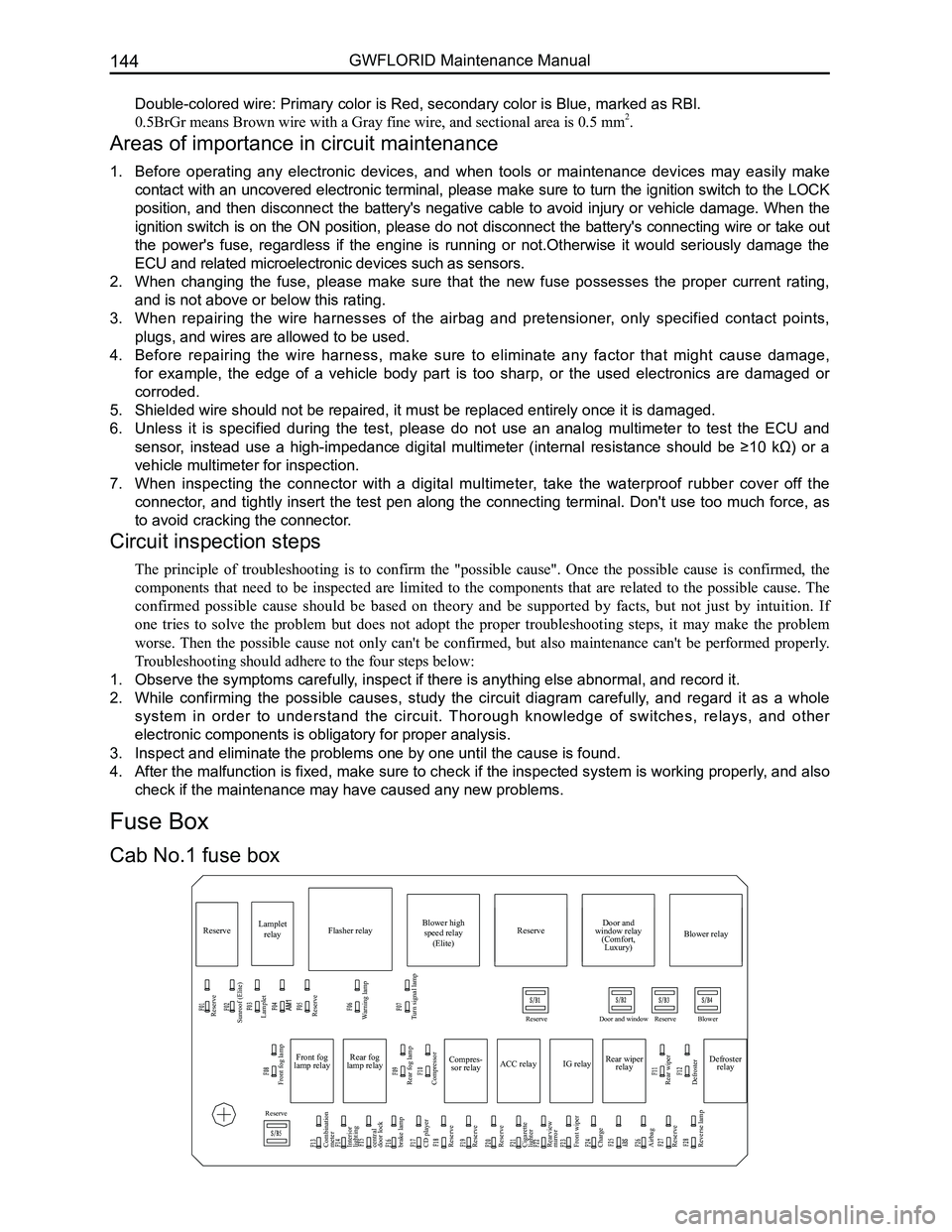
Compres-
sor relay
Reserve
Sunroof (Elite) Lamplet
Reserve
Reserve
Reserve
Reserve Door and window Reserve Blower
Lamplet
relay Flasher relay Blower high
speed relay (Elite) Door and
window relay (Comfort, Luxury) Blower relay
Reserve
Front fog lamp
Combination
meter
Interior
lighting
central
door lock
brake lamp
CD player
Reserve
Reserve
Reserve
Cigarette
lighter
Rearview
mirror
Front wiper
Charge
Airbag
Reserve
Reverse lamp Rear fog lamp
Rear wiper
Defroster Compressor
ACC relay
IG relayRear wiper
relay Defroster
relay
Front fog
lamp relay Rear fog
lamp relay
Warning lamp
Turn signal lamp
Cab No.1 fuse box
Fuse Box
Page 152 of 281

Downloaded from www.Manualslib.com manuals search engine 145Vehicle Body Electronic System
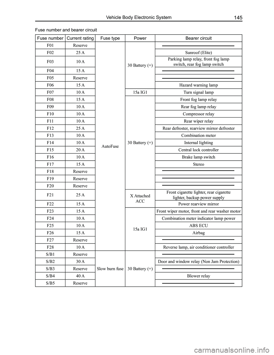
Fuse numberCurrent ratingFuse typePowerBearer circuit
F01Reserve
AutoFuse
30 Battery (+)
F0225 ASunroof (Elite)
F0310 AParking lamp relay, front fog lamp
switch, rear fog lamp switch
F0415 A
F05Reserve
F0615 AHazard warning lamp
F0710 A15a IG1 Turn signal lamp
F0815 A
30 Battery (+)
Front fog lamp relay
F0910 ARear fog lamp relay
F1010 ACompressor relay
F1110 ARear wiper relay
F1225 ARear defroster, rearview mirror defroster
F1310 ACombination meter
F1410 AInternal lighting
F1520 ACentral lock controller
F1610 ABrake lamp switch
F1715 AStereo
F18Reserve
F19Reserve
F20Reserve
F2125 AX Attached
ACC
Front cigarette lighter, rear cigarette
lighter, backup power supply
F2215 APower rearview mirror
F2315 A
15a IG1
Front wiper motor, front and rear washer motor
F2410 ACombination meter indicator lamp power
F2510 AABS ECU
F2615 AAirbag
F27Reserve
F2810 AReverse lamp, air conditioner controller
S/B1Reserve
Slow burn fuse 30 Battery (+)
S/B230 ADoor and window relay (Non Jam Protection)
S/B3Reserve
S/B440 ABlower relay
S/B5Reserve
Fuse number and bearer circuit
Page 155 of 281

Downloaded from www.Manualslib.com manuals search engine GWFLORID Maintenance Manual148
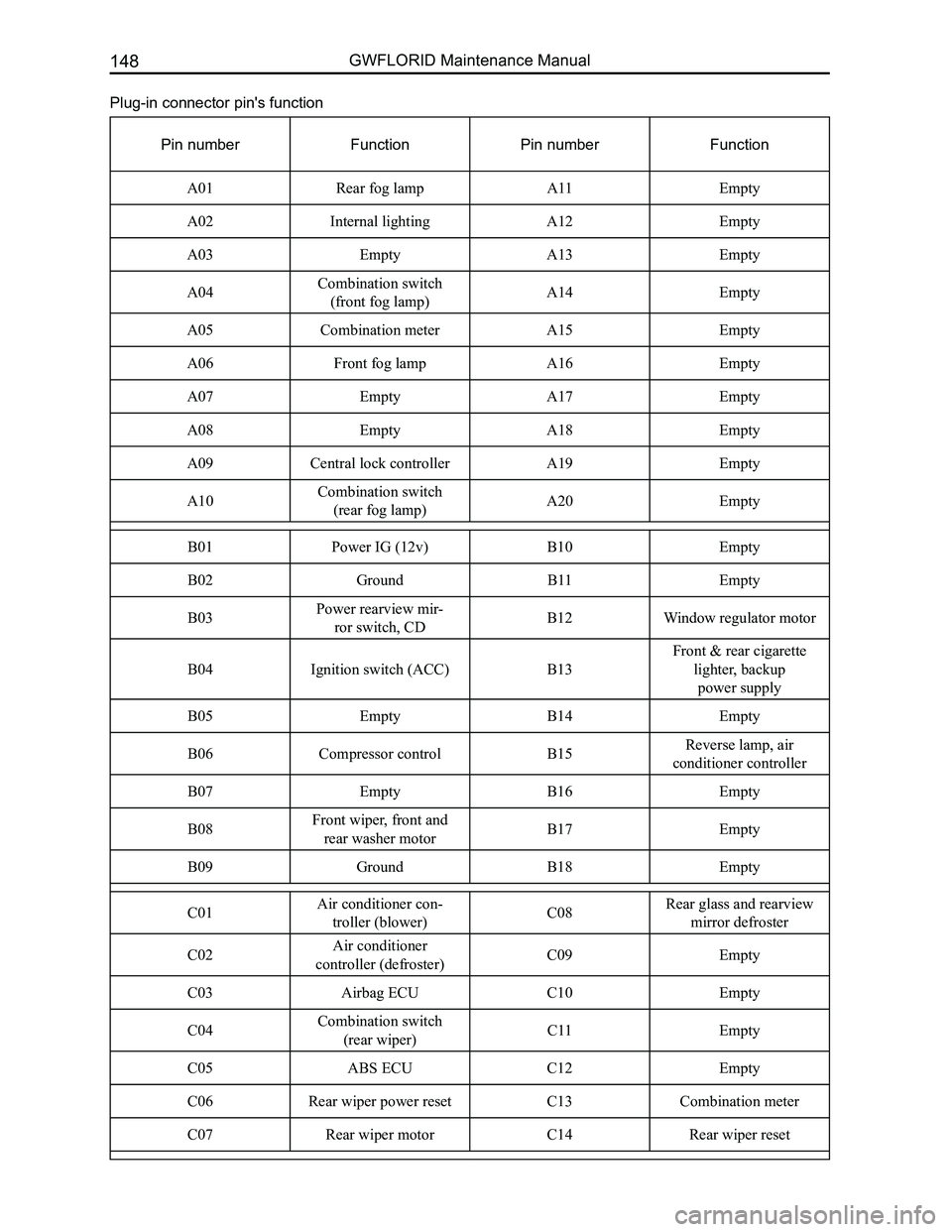
Plug-in connector pin's function
Pin numberFunctionPin numberFunction
A01Rear fog lampA11Empty
A02Internal lightingA12Empty
A03EmptyA13Empty
A04Combination switch
(front fog lamp)A14Empty
A05Combination meter A15Empty
A06Front fog lampA16Empty
A07EmptyA17Empty
A08EmptyA18Empty
A09Central lock controllerA19Empty
A10Combination switch
(rear fog lamp)A20Empty
B01Power IG (12v)B10Empty
B02GroundB11Empty
B03Power rearview mir-
ror switch, CDB12Window regulator motor
B04Ignition switch (ACC)B13
Front & rear cigarette
lighter, backup
power supply
B05EmptyB14Empty
B06Compressor controlB15Reverse lamp, air
conditioner controller
B07EmptyB16Empty
B08Front wiper, front and
rear washer motorB17Empty
B09GroundB18Empty
C01Air conditioner con-
troller (blower) C08Rear glass and rearview
mirror defroster
C02Air conditioner
controller (defroster) C09Empty
C03Airbag ECU C10Empty
C04Combination switch
(rear wiper) C11Empty
C05ABS ECUC12Empty
C06Rear wiper power resetC13Combination meter
C07Rear wiper motorC14Rear wiper reset
Page 160 of 281

Downloaded from www.Manualslib.com manuals search engine 153Vehicle Body Electronic System
High mounted brake lamp
Rear defroster positiveRear wiper motor
Trunk lock motor, door lamp switch
Opener switchRear defroster negative
Theft deterrent indicator lampCombination meter CD/DVD
Air conditioner speed adjuster, AC switch, rear defroster switch
Air conditioner temperature sensorF r o n t P a s s e n g e r s i d e airbag assembly
BlowerGlove box lighting
Cigarette lighter and lighting
Airbag ECU assembly 2
Diagnostic port
Acceleration pedal
Power rearview mirror switch, light brightness regulator
Trunk door wire harness
Central lock controller
Dashboard wire harness
Page 161 of 281

Downloaded from www.Manualslib.com manuals search engine GWFLORID Maintenance Manual154
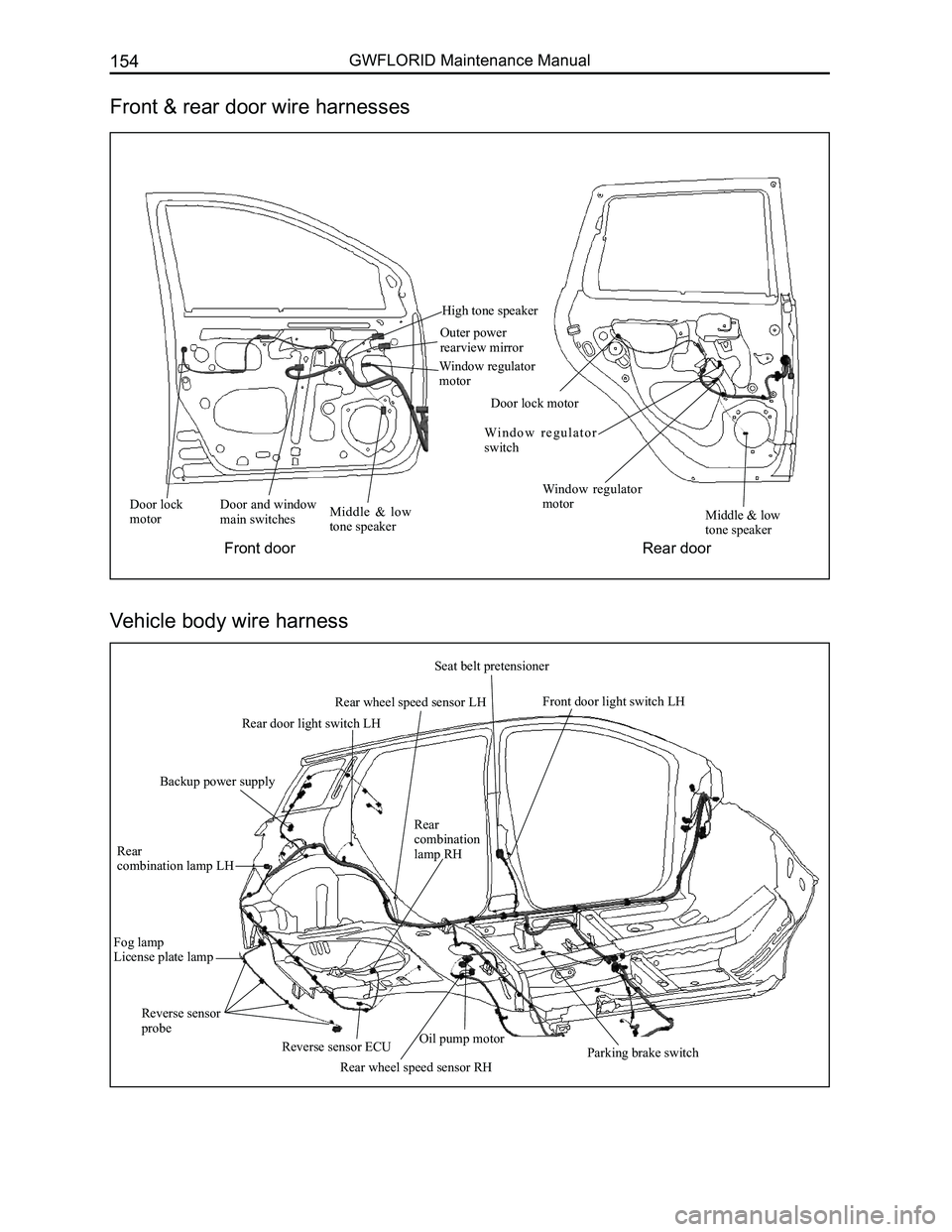
Door lock motorDoor and window main switchesMiddle & low tone speaker
High tone speaker
Outer power rearview mirror
Window regulator motor
Door lock motor
Wi n d o w r e g u l a t o r switch
Window regulator motorMiddle & low tone speaker
Fog lampLicense plate lamp
Rear
combination lamp LH
Rear combination lamp RH
Rear wheel speed sensor RHParking brake switch
Front door light switch LH
Seat belt pretensioner
Rear wheel speed sensor LH
Rear door light switch LH
Backup power supply
Front & rear door wire harnesses
Vehicle body wire harness
Front doorRear door
Reverse sensor ECU
Reverse sensor probeOil pump motor
Page 162 of 281

Downloaded from www.Manualslib.com manuals search engine 155Vehicle Body Electronic System
Condenser fan motor
Connected compressor
Oil pressure switch
Front oxygen sensor
Connected reverse switch
Connected engine speed sensor Connected
ignition coil
Connected speed sensor Connected coolant temp. sensor
Canister control valve
Connected combination meter A
Connected antenna
Diagnostic port
Connected AC switch Connected air conditioner temperature sensor
Front passenger side airbag
Connected speed adjustive resistance, blower
Front window regulator RH
Front window regulator switch RH
Front medium woofer RH
Front tweeter LH Right outer electric mirror
Front passenger side central door lock switch
Front door lamp switch RH
Front passenger seat belt pretensioner Front door lock motor RH
Ground
plate 3
Connected cigarette lighter (lighting)
Connected cigarette lighter
Front passenger seat belt switch
Connected parking brake switch Connected air conditioner governor & front
passenger seat belt unfastened indicator lamp
Connected CD player
Connected engine ECUConnected ground P1#
Connected ground P2#
Connected starter
Connected knock sensor
Connected starter field coil
Connected inlet
temperature pressure
sensor
connected
electronic throttle
Rear oxygen sensor
Connected 4th
cylinder injection
nozzle
Connected 3rd
cylinder injection
nozzle
Connected 2nd
cylinder injection
nozzle
Connected 1st
cylinder
injection nozzle
Connected generator
Connected engine armature Connected front combination lamp RH
Connected front fog lamp RH
Connected rear washer motor
Connected front washer motor
Connected front wheel speed sensor RH
Right ground
Connected A/C pressure switch
Connected phase sensor
Connected low
pitched horn
Connected front
combination lamp LH
Rediator fan motor
Connected front
fog lamp LH
Connected high pitched horn
Battery
negative
Body
ground
Battery
Left ground Connected
brake lamp
switch Connected brake fluid warning switch
Connected theft deterrent indicator Theft deterrent ECU 1Connected lock
cylinder lightConnected ignition
switch (white)
The key is inserted into the switch
Right combination switch (wiper) Connected airbag ECU (yellow)Ground
plate 2
Ground
plate 4
Connected accelerator pedal
Ground plate 1
Left outer electric mirror
Front medium woofer LH Front door lock motor LH
Rear medium woofer LH
Rear window regulator switch LH
Rear door lock motor LH Rear door lamp switch LH
Ground point ACapacitor
Vehicle power supply
Rear fog lamp LH Left license plate lamp
High mounted brake lamp
Ground point Trunk opener switch
Trunk motorRear wiper motor
Rear windshield defroster “-”
Trunk lamp switch Right license plate lamp
Rear fog lamp RH
Rear combination lamp RHRear wheel speed sensor RH
Rear window
regulator RH
Rear window
regulator switch RH
Rear door lock motor RH
Rear door lamp switch RH Rear medium woofer RH
Ground point B
Rear combination lamp LH
Rear windshield defroster “+”
Rear wheel speed
sensor LH
Rear window regulator LH
Fuel pump, fuel sensor
Rear interior dome lamp
Front door lamp
switch LH
Driver seat belt pretensioner Driver seat belt switch
Front tweeter LH
Connected light brightness regulator switch
Connected rearview mirror switch (white)
Connected glove box lamp
Front window regulator LH Left combination switch (light)
Connected main airbag, horn switch
Window regulator mainly
control switch, central door
lock mainly control switch Connected central door lock controller (white)
Connected front wiper motor
Connected clutch
switch
Connected ABS ECUBattery
positive
Connected front wheel
speed sensor LH Engine groud
Starter connect to
battery positive
Generator connect to
battery positive
Wire Harness Relationship and Plug-in Connections Numbered Diagram
Page 177 of 281

Downloaded from www.Manualslib.com manuals search engine GWFLORID Maintenance Manual170
Air conditioning and defrosting system
Rear window defroster
Connected position lamp relay Manually AC control sysytem
Defroster system Electric AC control system
Connected air conditioner
pressure switch
Blower relay
Air conditioner
panel lighting Defroster switch
Rear defroster indicator
Left outer rearview mirror defroster
Right outer rearview mirror defroster
Front passenger seat belt switch Defroster relay
To flasher relay
Blower relay Blower regulate module
Blower high speed relay
Rear defroster indicator
Front passenger seat belt unfastened indicator lamp
Air conditioner wind speed switch
Blower Speed adjustive
resistance
Rear defroster & alarm switch
(comfort, luxury) Right outer electric rearview mirror defroster (Elite) Left outer electric rearviewmirror
defroster (Elite) Front passenger seat
belt switch Connected speed adjustive resistance,
blower (Comfort, luxury) Connected rear
window defroster Connected cycle damper
actuator (Elite) Connected blower regulate
module (Elite) Connected temperature regulation
damper actuator (Elite)
AC switch (comfort, luxury)
Connected electric AC controller (Elite)
Connected AC governor & front
passenger seat belt unfastened indicator
lamp (comfort, luxury) Connected mode damper actuator (Elite) Connected blower (Elite)
Mode damper actuator
Cycle damper actuator Temperature regulation
damper actuator
Manually
air
conditioner
Electric AC controller
AC switch
Off
On Off On Terminal
Terminal Terminal
Location Location
Location