2008 GREAT WALL FLORID engine oil
[x] Cancel search: engine oilPage 112 of 281

Downloaded from www.Manualslib.com manuals search engine 105Brake System
3. Remove the check valve assembly.
Pull out the check valve and valve seat from the vacuum
booster's front case as shown on the left.
Disassembling the vacuum booster with
brake cylinder assembly
1. Brake master pump removal.
Take down the lock nuts between the fixed brake master
pump and front case with a M13 sleeve, and then forcibly
pull out the brake master pump.
Caution: Do not lose the rectangular sealing ring.
2. Remove the brake reservoir assembly.
Push out the elastic cylindrical pin from the hole of the oil
cup’s foot with a suitably sized screwdriver, and then pull
out the oil cup from the pump in the direction as shown on
the left. If necessary to take off the brake reservoir cover,
twist it off manually.
6. Screw off the coupling bolt between the vacuum booster
and the pedal bracket with a M13 sleeve.
7. Extract the vacuum booster with brake cylinder assem-
bly.
Removal of the vacuum booster with brake cylinder assembly
is now complete.
Check valveCheck valve seat
Lock nutRectangular sealing ring
Elastic cylindrical pin
Bolt
Page 114 of 281
Downloaded from www.Manualslib.com manuals search engine 107Brake System
Anti-lock Brake System
ABS/EBD introduction
1. Operation
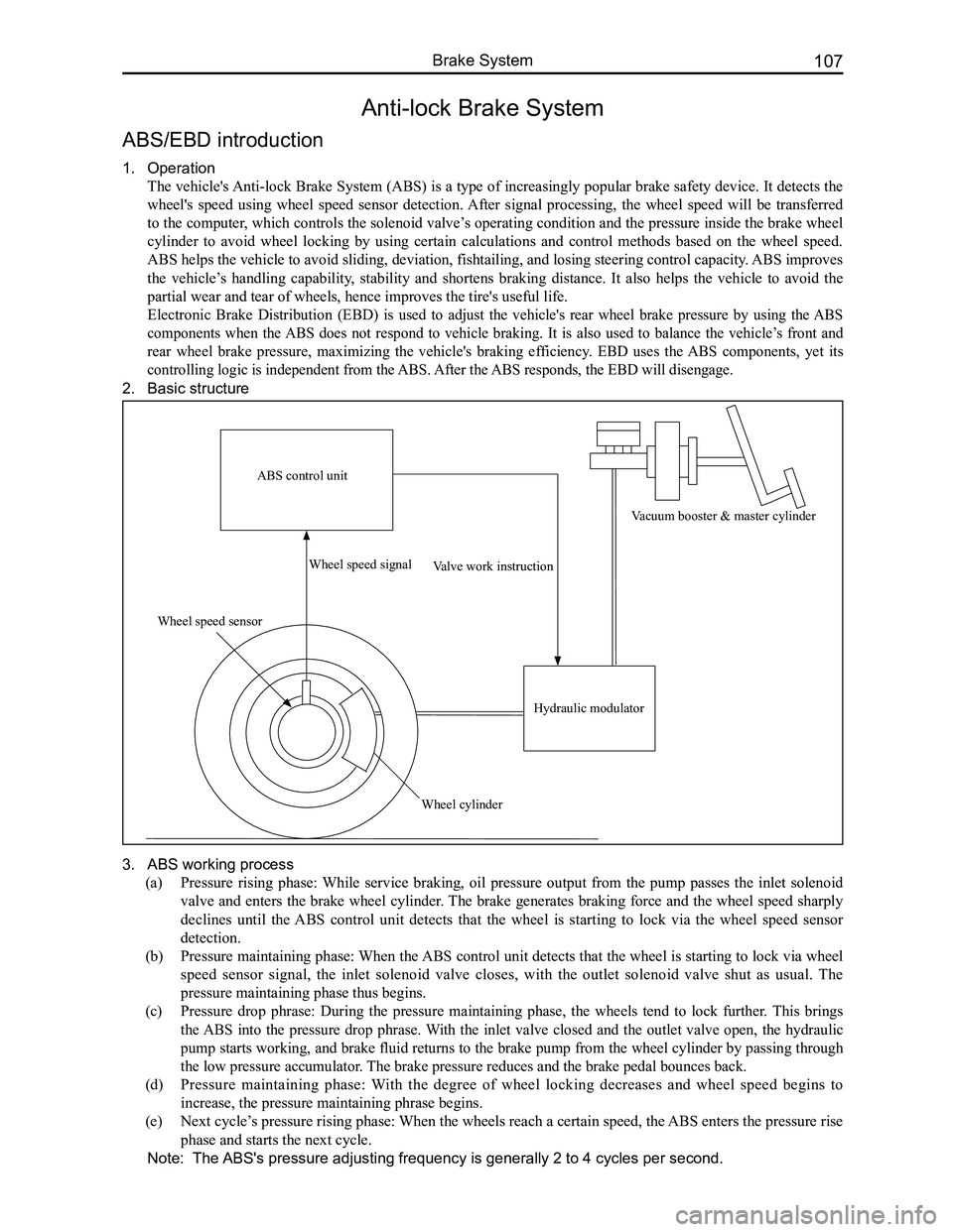
The vehicle's Anti-lock Brake System (ABS) is a type of increasingly popular brake safety device. It detects the
wheel's speed using wheel speed sensor detection. After signal processing, the wheel speed will be transferred
to the computer, which controls the solenoid valve’s operating condition and the pressure inside the brake wheel
cylinder to avoid wheel locking by using certain calculations and control methods based on the wheel speed.
ABS helps the vehicle to avoid sliding, deviation, fishtailing, and losing steering control capacity. ABS improves
the vehicle’s handling capability, stability and shortens braking distance. It also helps the vehicle to avoid the
partial wear and tear of wheels, hence improves the tire's useful life.
Electronic Brake Distribution (EBD) is used to adjust the vehicle's rear wheel brake pressure by using the ABS
components when the ABS does not respond to vehicle braking. It is also used to balance the vehicle’s front and
rear wheel brake pressure, maximizing the vehicle's braking efficiency. EBD uses the ABS components, yet its
controlling logic is independent from the ABS. After the ABS responds, the EBD will disengage.
2. Basic structure
3. ABS working process
(a) Pressure rising phase: While service braking, oil pressure output from the pump passes the inlet solenoid
valve and enters the brake wheel cylinder. The brake generates braking force and the wheel speed sharply
declines until the ABS control unit detects that the wheel is starting to lock via the wheel speed sensor
detection.
(b) Pressure maintaining phase: When the ABS control unit detects that the wheel is starting to lock via wheel
speed sensor signal, the inlet solenoid valve closes, with the outlet solenoid valve shut as usual. The
pressure maintaining phase thus begins.
(c) Pressure drop phrase: During the pressure maintaining phase, the wheels tend to lock further. This brings
the ABS into the pressure drop phrase. With the inlet valve closed and the outlet valve open, the hydraulic
pump starts working, and brake fluid returns to the brake pump from the wheel cylinder by passing through
the low pressure accumulator. The brake pressure reduces and the brake pedal bounces back.
(d) Pressure maintaining phase: With the degree of wheel locking decreases and wheel speed begins to
increase, the pressure maintaining phrase begins.
(e) Next cycle’s pressure rising phase: When the wheels reach a certain speed, the ABS enters the pressure rise
phase and starts the next cycle.
Note: The ABS's pressure adjusting frequency is generally 2 to 4 cycles per second.
ABS control unit
Wheel speed sensor
Wheel speed signal
Wheel cylinder
Valve work instruction
Hydraulic modulator
Vacuum booster & master cylinder
Page 118 of 281
Downloaded from www.Manualslib.com manuals search engine 111Brake System
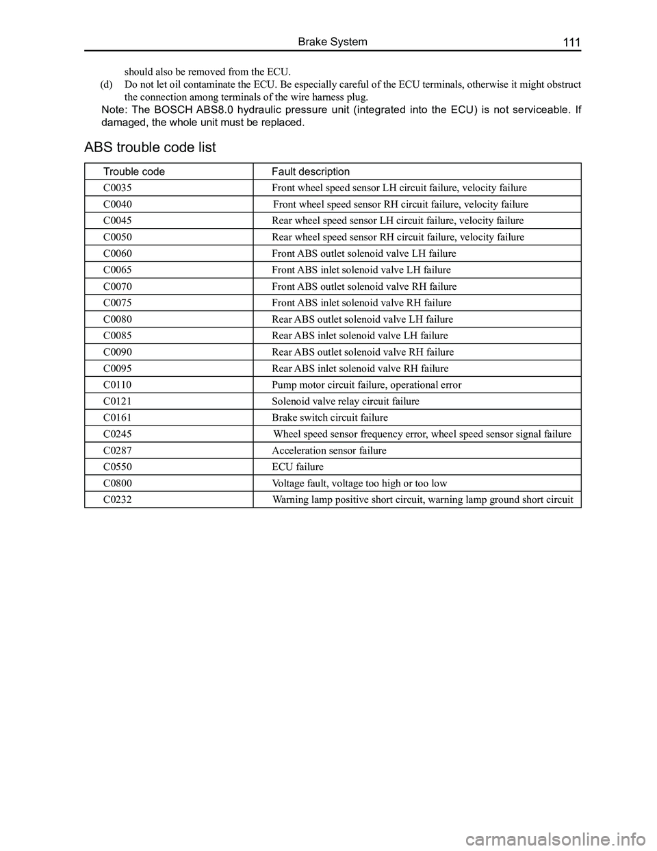
ABS trouble code list
Trouble codeFault description
C0035Front wheel speed sensor LH circuit failure, velocity failure
C0040Front wheel speed sensor RH circuit failure, velocity failure
C0045Rear wheel speed sensor LH circuit failure, velocity failure
C0050Rear wheel speed sensor RH circuit failure, velocity failure
C0060Front ABS outlet solenoid valve LH failure
C0065Front ABS inlet solenoid valve LH failure
C0070Front ABS outlet solenoid valve RH failure
C0075Front ABS inlet solenoid valve RH failure
C0080Rear ABS outlet solenoid valve LH failure
C0085Rear ABS inlet solenoid valve LH failure
C0090Rear ABS outlet solenoid valve RH failure
C0095Rear ABS inlet solenoid valve RH failure
C0110Pump motor circuit failure, operational error
C0121Solenoid valve relay circuit failure
C0161Brake switch circuit failure
C0245Wheel speed sensor frequency error, wheel speed sensor signal failure
C0287Acceleration sensor failure
C0550ECU failure
C0800Voltage fault, voltage too high or too low
C0232Warning lamp positive short circuit, warning lamp ground short circuit
should also be removed from the ECU.
(d) Do not let oil contaminate the ECU. Be especially careful of the ECU terminals, otherwise it might obstruct
the connection among terminals of the wire harness plug.
Note: The BOSCH ABS8.0 hydraulic pressure unit (integrated into the ECU) is not serviceable. If
damaged, the whole unit must be replaced.
Page 127 of 281
Downloaded from www.Manualslib.com manuals search engine GWFLORID Maintenance Manual120
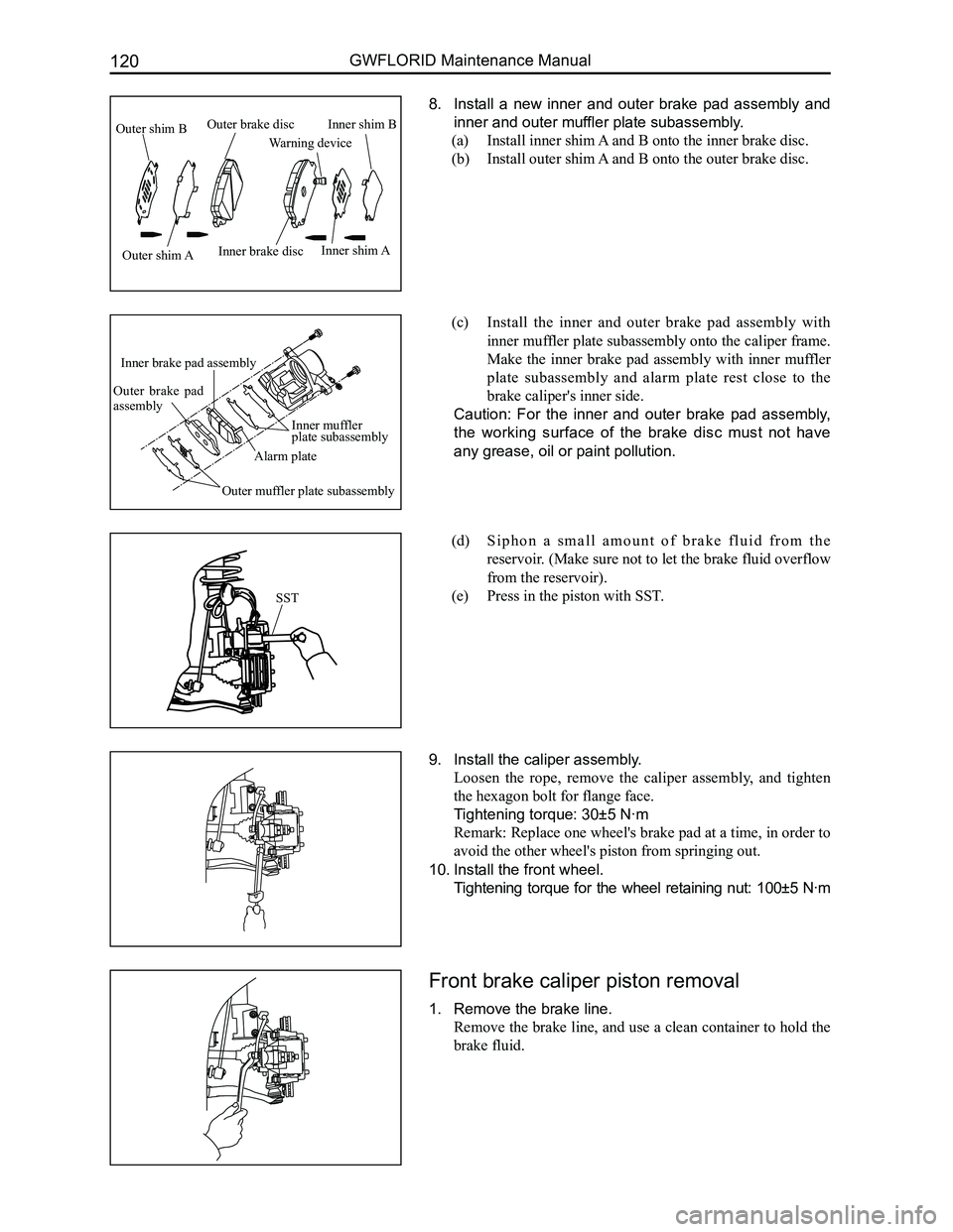
8. Install a new inner and outer brake pad assembly and
inner and outer muffler plate subassembly.
(a) Install inner shim A and B onto the inner brake disc.
(b) Install outer shim A and B onto the outer brake disc.
(c) Install the inner and outer brake pad assembly with
inner muffler plate subassembly onto the caliper frame.
Make the inner brake pad assembly with inner muffler
plate subassembly and alarm plate rest close to the
brake caliper's inner side.
Caution: For the inner and outer brake pad assembly,
the working surface of the brake disc must not have
any grease, oil or paint pollution.
(d) S i p h o n a s m a l l a m o u n t o f b r a k e f l u i d f r o m t h e
reservoir. (Make sure not to let the brake fluid overflow
from the reservoir).
(e) Press in the piston with SST.
9. Install the caliper assembly.
Loosen the rope, remove the caliper assembly, and tighten
the hexagon bolt for flange face.
Tightening torque: 30±5 N·m
Remark: Replace one wheel's brake pad at a time, in order to
avoid the other wheel's piston from springing out.
10. Install the front wheel.
Tightening torque for the wheel retaining nut: 100±5 N·m
Front brake caliper piston removal
1. Remove the brake line.
Remove the brake line, and use a clean container to hold the
brake fluid.
SST
Outer shim B
Outer shim AInner brake disc
Warning device
Inner shim B
Inner shim A
Outer brake disc
Inner muffler plate subassembly
Alarm plate
Inner brake pad assembly
Outer brake pad assembly
Outer muffler plate subassembly
Page 137 of 281

Downloaded from www.Manualslib.com manuals search engine GWFLORID Maintenance Manual130
7. Install the brake cable connector on the brake trailing
shoe with brake lever assembly.
(a) Install the brake cable connector on the brake trailing
shoe with brake lever assembly.
(b) Insert the brake trailing shoe with brake lever assembly
and the shoe end of the brake leading shoe assembly
into the wheel cylinder assembly.
Remark: Do not let oil or grease drip on the brake shoe's
lining.
8. Install the retainer spring.
9. Install the brake leading and trailing shoe assemblies
onto the brake back plate assembly.
(a) Insert the pressure spring bar into the brake back plate
assembly and brake leading and trailing shoe assemblies.
(b) Put the pressure spring on the pressure spring bar,
put in the pressure spring cap, and use SST (Special
Service Tools) to lock the pressure spring cap onto the
pressure spring bar.
10. Inspect the operating procedures of the automatic ad-
juster.
(a) Refer to the diagram for directions, step on and off the
brake pedal, and make sure the self-adjusting screws
can rotate. If they are unable to rotate, inspect the rear
brake to try to determine the source of the problem.
(b) Adjust the adjusting mechanisms length and make it as
short as possible.
(c) Install the rear brake drum.
(d) Press the brake pedal towards the floor until a clicking
noise cannot be heard.
11. Inspect the space between the brake's friction plate
and rear brake drum.
(a) Remove the rear brake drum.
(b) Measure the rear brake drum's internal diameter and
the brake shoe friction plate's external diameter, and
inspect if the difference between the two diameters is
within the regulated clearance range.
Single sided clearance: 0.25 mm
If not correct, inspect the braking system.
12. Install the rear wheel.
Tightening torque: 100 N·m
13. Fill the brake fluid reservoir up with brake fluid and
exhaust the air out of the brake system.
14. Check for leaking brake fluid
SST
Page 142 of 281
Downloaded from www.Manualslib.com manuals search engine 135Steering System
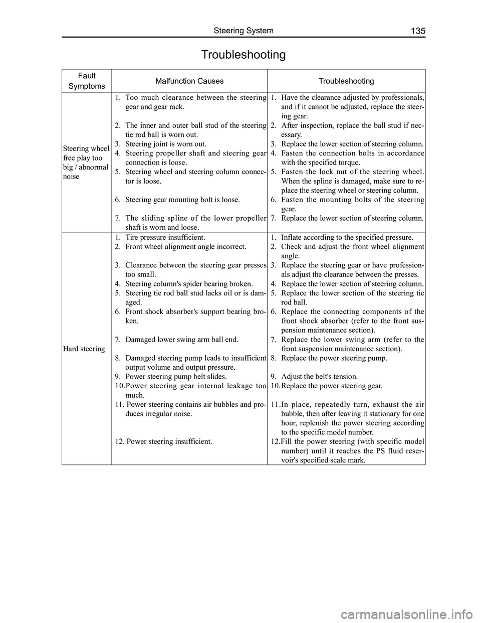
Troubleshooting
Fault
SymptomsMalfunction CausesTroubleshooting
Steering wheel
free play too
big / abnormal
noise
1. Too much clearance between the steering
gear and gear rack.
2. The inner and outer ball stud of the steering
tie rod ball is worn out.
3. Steering joint is worn out.
4. Steering propeller shaft and steering gear
connection is loose.
5. Steering wheel and steering column connec-
tor is loose.
6. Steering gear mounting bolt is loose.
7. The sliding spline of the lower propeller
shaft is worn and loose.
1. Have the clearance adjusted by professionals,
and if it cannot be adjusted, replace the steer-
ing gear.
2. After inspection, replace the ball stud if nec-
essary.
3. Replace the lower section of steering column.
4. Fasten the connection bolts in accordance
with the specified torque.
5. Fasten the lock nut of the steering wheel.
When the spline is damaged, make sure to re-
place the steering wheel or steering column.
6. Fasten the mounting bolts of the steering
gear.
7. Replace the lower section of steering column.
Hard steering
1. Tire pressure insufficient.
2. Front wheel alignment angle incorrect.
3. Clearance between the steering gear presses
too small.
4. Steering column's spider bearing broken.
5. Steering tie rod ball stud lacks oil or is dam-
aged.
6. Front shock absorber's support bearing bro-
ken.
7. Damaged lower swing arm ball end.
8. Damaged steering pump leads to insufficient
output volume and output pressure.
9. Power steering pump belt slides.
10.Power steering gear internal leakage too
much.
11. Power steering contains air bubbles and pro-
duces irregular noise.
12. Power steering insufficient.
1. Inflate according to the specified pressure.
2. Check and adjust the front wheel alignment
angle.
3. Replace the steering gear or have profession-
als adjust the clearance between the presses.
4. Replace the lower section of steering column.
5. Replace the lower section of the steering tie
rod ball.
6. Replace the connecting components of the
front shock absorber (refer to the front sus-
pension maintenance section).
7. Replace the lower swing arm (refer to the
front suspension maintenance section).
8. Replace the power steering pump.
9. Adjust the belt's tension.
10. Replace the power steering gear.
11.In place, repeatedly turn, exhaust the air
bubble, then after leaving it stationary for one
hour, replenish the power steering according
to the specific model number.
12.Fill the power steering (with specific model
number) until it reaches the PS fluid reser-
voir's specified scale mark.
Page 143 of 281

Downloaded from www.Manualslib.com manuals search engine GWFLORID Maintenance Manual136
Fault
SymptomsMalfunction CausesTroubleshooting
Poor steering
return
Straight
movement
stability poor
1. Tire pressure insufficient.
2. Wheel counterweight falls off or other fac-
tors cause extremely poor wheel balance.
3. Lower swing arm's rubber bushing is too old,
big difference between the left and right's
rigidity.
4. The front shock absorber's support bearing
and lower swing arm ball lacks sufficient lu-
brications.
5. The four wheels' positional parameters incor-
rect.
6. Steering gear's gear rack meshing condition
worsens and causes intense reverse resis-
tance.
7. Steering column bearing and spider bearing
damaged.
8. Power steering pump's oil supply insuffi-
cient.
9. Inner portion of the steering gear's control
valve performance degradation.
1. Inflate according to the specified pressure.
2. Recalibrate the wheel's dynamic balance.
3. Replace the lower swing arm.
4. Fill with grease of the specified model num-
ber.
5. Re-measure and adjust the four wheels' posi-
tional parameters.
6. Replace the steering gear.
7. Replace the steering column assembly.
8. Replace the power steering pump.
9. Replace the power steering gear.
Page 147 of 281
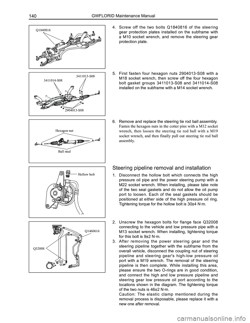
Downloaded from www.Manualslib.com manuals search engine GWFLORID Maintenance Manual140
4. Screw off the two bolts Q1840816 of the steering
gear protection plates installed on the subframe with
a M10 socket wrench, and remove the steering gear
protection plate.
5. First fasten four hexagon nuts 2904013-S08 with a
M18 socket wrench, then screw off the four hexagon
bolt gasket groups 3411013-S08 and 3411014-S08
installed on the subframe with a M14 socket wrench.
6. Remove and replace the steering tie rod ball assembly.
Fasten the hexagon nuts in the cotter pins with a M12 socket
wrench, then loosen the steering tie rod ball with a M19
socket wrench, and then finally pull out steering tie rod ball
assembly.
2. Unscrew the hexagon bolts for flange face Q32008
connecting to the vehicle and low pressure pipe with a
M13 socket wrench. When installing, tightening torque
for this bolt is 9±2 N·m.
3. A f t e r r e m o v i n g t h e p o w e r s t e e r i n g g e a r a n d t h e
steering pipeline together with the subframe from the
overall vehicle, disconnect the coupling nut of steering
pipeline and steering gear's high-low pressure oil
port with a M19 wrench. The removal of the steering
pipeline is then complete. While installing this area,
please ensure the two O-rings are in good condition,
and connect the high and low pressure pipeline and
steering gear low pressure oil port according to the
locations shown in the diagram. The tightening torque
of the two nuts is 46±2 N·m.
C a u t i o n : T h e e l a s t i c c l a m p m e n t i o n e d d u r i n g t h e
removal process is disposable, please replace it with a
new one after removal.
Q1460616
Q32008
Q1840816
2904013-S08
3411014-S08
3411013-S08
Hexagon nut
Ball stud
Steering pipeline removal and installation
1. Disconnect the hollow bolt which connects the high
pressure oil pipe and the power steering pump with a
M22 socket wrench. When installing, please take note
of the two seal gaskets and do not allow the oil pump
port to loosen. Each of the seal gaskets should be
positioned at either side of the high pressure oil ring.
Tightening torque for the hollow bolt is 30±4 N·m.
Hollow bolt