Page 27 of 281

Downloaded from www.Manualslib.com manuals search engine GWFLORID Maintenance Manual20
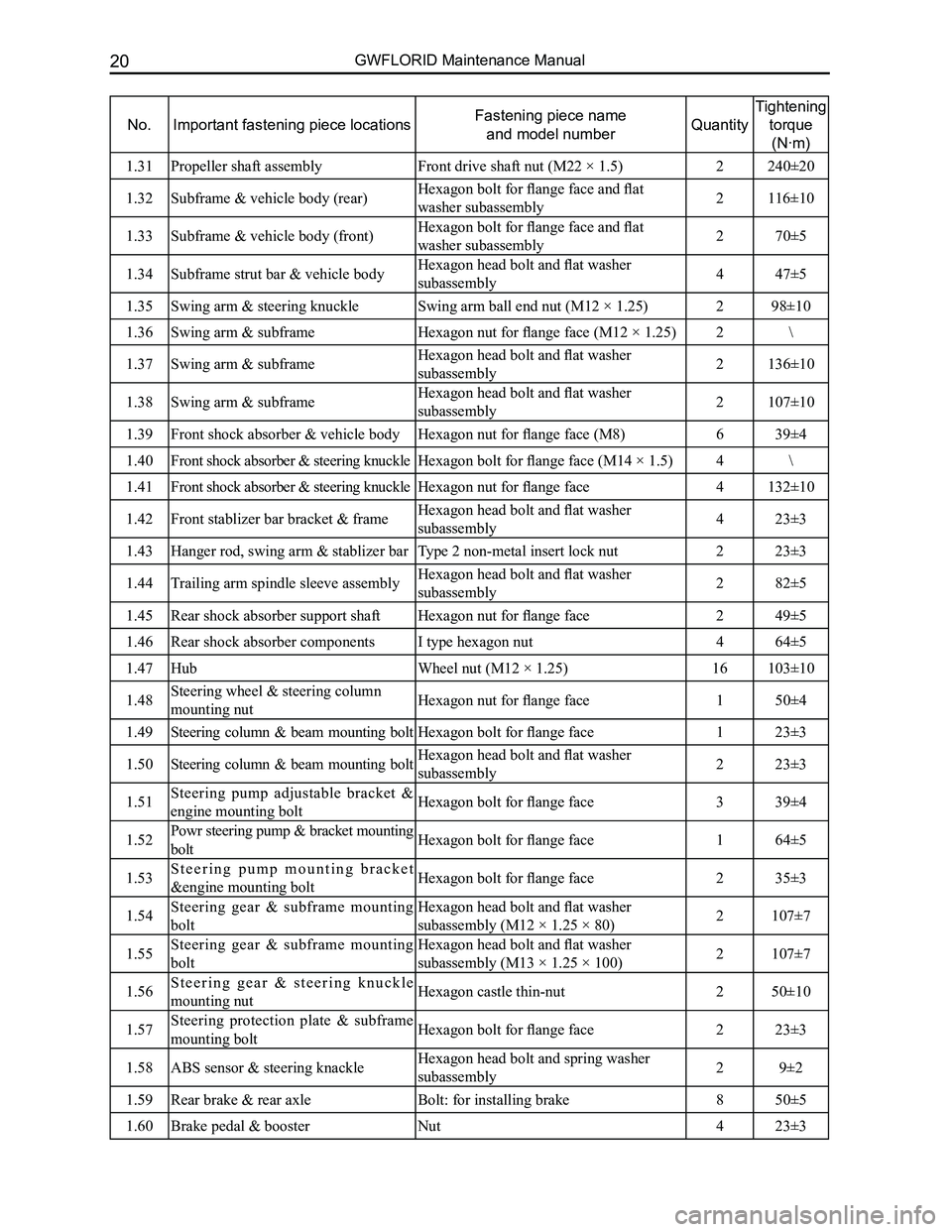
No.Important fastening piece locationsFastening piece name
and model numberQuantity
Tightening
torque
(N·m)
1.31Propeller shaft assemblyFront drive shaft nut (M22 × 1.5)2240±20
1.32Subframe & vehicle body (rear)Hexagon bolt for flange face and flat
washer subassembly2116±10
1.33Subframe & vehicle body (front)Hexagon bolt for flange face and flat
washer subassembly270±5
1.34Subframe strut bar & vehicle bodyHexagon head bolt and flat washer
subassembly447±5
1.35Swing arm & steering knuckleSwing arm ball end nut (M12 × 1.25)298±10
1.36Swing arm & subframeHexagon nut for flange face (M12 × 1.25)2\
1.37Swing arm & subframeHexagon head bolt and flat washer
subassembly2136±10
1.38Swing arm & subframeHexagon head bolt and flat washer
subassembly2107±10
1.39Front shock absorber & vehicle bodyHexagon nut for flange face (M8)639±4
1.40Front shock absorber & steering knuckleHexagon bolt for flange face (M14 × 1.5)4\
1.41Front shock absorber & steering knuckleHexagon nut for flange face4132±10
1.42Front stablizer bar bracket & frameHexagon head bolt and flat washer
subassembly423±3
1.43Hanger rod, swing arm & stablizer barType 2 non-metal insert lock nut223±3
1.44Trailing arm spindle sleeve assemblyHexagon head bolt and flat washer
subassembly282±5
1.45Rear shock absorber support shaftHexagon nut for flange face249±5
1.46Rear shock absorber componentsI type hexagon nut464±5
1.47Hub Wheel nut (M12 × 1.25)16103±10
1.48Steering wheel & steering column
mounting nutHexagon nut for flange face150±4
1.49Steering column & beam mounting boltHexagon bolt for flange face123±3
1.50Steering column & beam mounting boltHexagon head bolt and flat washer
subassembly223±3
1.51Steering pump adjustable bracket &
engine mounting boltHexagon bolt for flange face339±4
1.52Powr steering pump & bracket mounting
boltHexagon bolt for flange face164±5
1.53S t e e r i n g p u m p m o u n t i n g b r a c k e t
&engine mounting boltHexagon bolt for flange face235±3
1.54Steering gear & subframe mounting
bolt
Hexagon head bolt and flat washer
subassembly (M12 × 1.25 × 80)2107±7
1.55Steering gear & subframe mounting
bolt
Hexagon head bolt and flat washer
subassembly (M13 × 1.25 × 100)2107±7
1.56S t e e r i n g g e a r & s t e e r i n g k n u c k l e
mounting nutHexagon castle thin-nut250±10
1.57Steering protection plate & subframe
mounting boltHexagon bolt for flange face223±3
1.58ABS sensor & steering knackleHexagon head bolt and spring washer
subassembly29±2
1.59Rear brake & rear axleBolt: for installing brake850±5
1.60Brake pedal & boosterNut423±3
Page 29 of 281

Downloaded from www.Manualslib.com manuals search engine GWFLORID Maintenance Manual22
Imaginary
reference line
Front wheel center line
Vehicle center line
"Z" represents the imaginary
reference line [below reference
l i n e ( " O Z " l i n e o f t h e d e s i g n
diagram) 400 mm]
Vehicle Body's Basic Calibration Measurements
This section shows the basic parameters of the overall vehicle. Please refer to this section when servicing or
repairing.
• All figures used to express measurements are actual figures.
• Measuring points are taken from the center of the mounting holes.
• When using the gauge, adjust the two measuring needles until they reach an equal length, then check
the measuring needle and the gauge itself to ensure there are no gaps.
• When using measuring tape, make sure not to stretch, twist, or bend it. \
• The asterisk (*) symbol after a numerical measurement value indicates that the other side's
symmetrical position is of equal value.
• Coordinates of the measuring points refer to the distances measured between the point and "X", "Y",
and "Z" standard lines.
• The left & right symmetry points of a measuring point's coordinate represent a coordinate point on the
left side, and that the right and left side are symmetrical.
Page 31 of 281
Downloaded from www.Manualslib.com manuals search engine GWFLORID Maintenance Manual24
Chassis
LH
side
Front
Front
UpperLower
Unit: mm
Page 33 of 281
Downloaded from www.Manualslib.com manuals search engine GWFLORID Maintenance Manual26
Subframe
Unit: mm
1195±1.5 ( Distance between the center points of both shaft's end surfaces \
)
1381±0.5 ( Distance between points P and Q )
Page 35 of 281
Downloaded from www.Manualslib.com manuals search engine GWFLORID Maintenance Manual28
MarkNameDiameter (mm)MarkNameDiameter (mm)
ACentral defroster air duct mounting holesΦ11BProcess cutOblong hole 7×12
CCentral defroster air duct mounting holesΦ8DProcess cutOblong hole 7×12
MarkNameDiameter (mm)MarkNameDiameter (mm)
ALeft D column inner decoration board laps over R angleBRight D column inner decoration board laps over R angle
CLeft combination taillight install panel connecting plate laps over R angleDRight combination taillight install panel connecting plate laps over R angle
Trunk door frame
Windshield
Page 37 of 281
Downloaded from www.Manualslib.com manuals search engine 30GWFLORID Maintenance Manual
Fuel Supply System
Components
Fuel filler hose III
Canister solenoid valve
Canister solenoid valve installation sheath
Canister solenoid valve mounting bracket assembly
Fuel hose sheath
Desorption fuel hose
Fuel filler hose
Desorption hose I
Fuel filler hose IIThree-hole clamp I
Charcoal canister
Fuel tank assembly
Fuel tank heat shield assembly
Charcoal canister air pipeAir return hose
Fuel filler pipe assembly
Electronic fuel pumpSingle-hole clampElectronic fuel pump install panel
Strengthening cushion
Fuel filler pipe connecting hose
Absorption hoseFuel filler pipe sleeve
Single-hole clamp
Fuel filter
Rear install buckle of fuel tank's heat shield
Fuel filler cap
Fuel filler hose I
Desorption hose III
Desorption hose II
Fuel filter mounting bracket assembly
Page 38 of 281

Downloaded from www.Manualslib.com manuals search engine 31Fuel Supply and Exhaust System
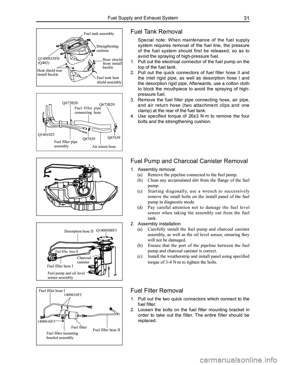
Fuel Tank Removal
Special note: When maintenance of the fuel supply
system requires removal of the fuel line, the pressure
of the fuel system should first be released, so as to
avoid the spraying of high-pressure fuel.
1. Pull out the electrical connector of the fuel pump on the
top of the fuel tank.
2. Pull out the quick connectors of fuel filler hose II and
the inlet rigid pipe, as well as desorption hose I and
the desorption rigid pipe. Afterwards, use a cotton cloth
to block the mouthpiece to avoid the spraying of high-
pressure fuel.
3. Remove the fuel filler pipe connecting hose, air pipe,
and air return hose (two attachment clips and one
clamp) at the rear of the fuel tank.
4. Use specified torque of 26±3 N·m to remove the four
bolts and the strengthening cushion.
Fuel Pump and Charcoal Canister Removal
1. Assembly removal
(a) Remove the pipeline connected to the fuel pump.
(b) Clean any accumulated dirt from the flange of the fuel
pump.
(c) Starting diagonally, use a wrench to successively
remove the small bolts on the install panel of the fuel
pump in diagnostic mode.
(d) Pay careful attention not to damage the fuel level
sensor when taking the assembly out from the fuel
tank.
2. Assembly installation
(a) Carefully install the fuel pump and charcoal canister
assembly, as well as the oil level sensor, ensuring they
will not be damaged.
(b) Ensure that the port of the pipeline between the fuel
pump and charcoal canister is correct.
(c) Install the weatherstrip and install panel using specified
torque of 3-4 N·m to tighten the bolts.
Fuel Filter Removal
1. Pull out the two quick connectors which connect to the
fuel filter.
2. Loosen the bolts on the fuel filter mounting bracket in
order to take out the filter. The entire filter should be
replaced.
Air return hose
Fuel filler pipe connecting hose
Fuel filler pipe assembly
Q1461025Q67639
Q673B20
Q67639
Q673B20
Fuel filler hose I1400616F3
Fuel filter mounting bracket assembly
Fuel filterFuel filler hose II
1400616F3
Desorption hose II
Fuel filler hose II
Fuel filler hose I
Charcoalcanister
Fuel pump and oil level sensor assembly
Q1400508F3
Strengthening cushion
Heat shield front install buckle
Fuel tank heat shield assembly
Heat shield rear install buckle
Fuel tank assembly
Q1400835FD(Q402)
Page 39 of 281
Downloaded from www.Manualslib.com manuals search engine GWFLORID Maintenance Manual32
Fuel Filler Pipe Assembly Removal
1. Remove the oil filler cap.
2. Screw off the fixed bolts connecting the fuel filler pipe
assembly bracket and vehicle body.
Air return hose
Fuel filler pipe connecting hose
Fuel filler pipe assembly
Q1461025Q67639
Q673B20
Q67639
Q673B20
Fuel filler pipe assembly
Fuel filler pipe sleeve
Fuel filler cap
3. Remove the attachment clips and clamps from the
fuel filler pipe connecting hose, air return hose, and air
pipe.
4. Remove the fuel filler pipe sleeve.