2008 GREAT WALL FLORID sensor
[x] Cancel search: sensorPage 81 of 281

Downloaded from www.Manualslib.com manuals search engine GWFLORID Maintenance Manual74
3. Remove the wheel speed sensor and the brake hose
Remove the wheel speed sensor's mounting bolts with a M10
sleeve to take off the wheel speed sensor. Remove the front
brake hose's mounting bolts with a M18 sleeve, and then
take off the brake hose.
Caution: When removing the brake hose, brake fluid
may flow out, catch the fluid with a container. Also,
b e c a u s e t h e b r a k e f l u i d i s c o r r o s i v e , p l e a s e p a y
attention to personal protection.
4. Remove the cotter pins and lock nuts of the steering tie
rod and the lower swing arm
Because the ball stud and steering knuckle act in conjunction
with the tapered bore, they can not yet be removed after re-
moving the nuts. Pound the steering knuckle arm (unfinished
surface) with a hammer. Positions are shown on the left.
Shake to loosen.
Caution:
1. To avoid separating the ball studs, do not pound the
tie rod and the lower swing arm with a hammer.
2. To avoid damaging the thread, do not hammer the
ball stud's head.
Front brake hose mounting bolt
Wheel speed sensor mounting bolts
Lightly hammer here
Page 82 of 281
Downloaded from www.Manualslib.com manuals search engine 75Suspension System
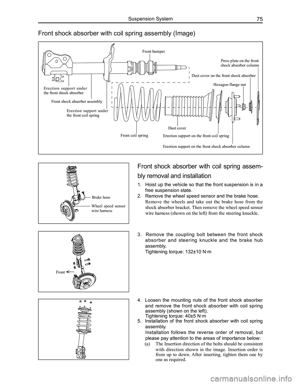
Front shock absorber with coil spring assembly (Image)
Front shock absorber with coil spring assem-
bly removal and installation
1. Hoist up the vehicle so that the front suspension is in a
free suspension state.
2. Remove the wheel speed sensor and the brake hose.
Remove the wheels and take out the brake hose from the
shock absorber bracket. Then remove the wheel speed sensor
wire harness (shown on the left) from the steering knuckle.
3. Remove the coupling bolt between the front shock
absorber and steering knuckle and the brake hub
assembly.
Tightening torque: 132±10 N·m
4. Loosen the mounting nuts of the front shock absorber
and remove the front shock absorber with coil spring
assembly (shown on the left).
Tightening torque: 40±5 N·m
5. Installation of the front shock absorber with coil spring
assembly.
Installation follows the reverse order of removal, but
please pay attention to the areas of importance below:
(a) The Insertion direction of the bolts should be consistent
with direction shown in the image. Insertion order is
from up to down. After inserting, tighten them one by
one as required.
Front
Brake hose
Wheel speed sensor wire harness
E r e c t i o n s u p p o r t u n d e r the front shock absorber
Front shock absorber assembly
Erection support under the front coil spring
Front coil spring
Dust cover
Erection support on the front shock absorber column
Hexagon flange nut
Press plate on the front shock absorber column
Dust cover on the front shock absorber
Erection support on the front coil spring
Front bumper
Page 102 of 281

Downloaded from www.Manualslib.com manuals search engine 95Brake System
Brake System Components Arrangement Schematics
Brake pedal assembly
Vacuum booster with brake cylinder assembly
Left steering knuckle and hub brake assembly
Left parking brake cable assembly
Rear brake assembly RHRear brake drum
Rear wheel speed sensor assembly RH
Right parking brake cable assembly
ABS controller assembly
Right steering knuckle and hub brake assembly
Brake line assembly
Rear wheel speed
sensor assembly LH
Front wheel speed sensor assembly RHFront wheel speed sensor assembly LH
Rear brake assembly LH
Parking brake control mechanism assembly
Page 114 of 281
Downloaded from www.Manualslib.com manuals search engine 107Brake System
Anti-lock Brake System
ABS/EBD introduction
1. Operation
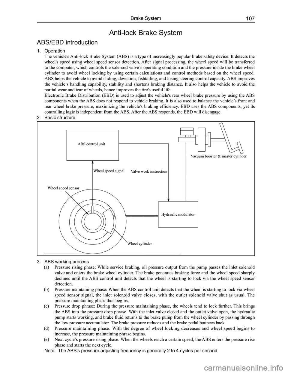
The vehicle's Anti-lock Brake System (ABS) is a type of increasingly popular brake safety device. It detects the
wheel's speed using wheel speed sensor detection. After signal processing, the wheel speed will be transferred
to the computer, which controls the solenoid valve’s operating condition and the pressure inside the brake wheel
cylinder to avoid wheel locking by using certain calculations and control methods based on the wheel speed.
ABS helps the vehicle to avoid sliding, deviation, fishtailing, and losing steering control capacity. ABS improves
the vehicle’s handling capability, stability and shortens braking distance. It also helps the vehicle to avoid the
partial wear and tear of wheels, hence improves the tire's useful life.
Electronic Brake Distribution (EBD) is used to adjust the vehicle's rear wheel brake pressure by using the ABS
components when the ABS does not respond to vehicle braking. It is also used to balance the vehicle’s front and
rear wheel brake pressure, maximizing the vehicle's braking efficiency. EBD uses the ABS components, yet its
controlling logic is independent from the ABS. After the ABS responds, the EBD will disengage.
2. Basic structure
3. ABS working process
(a) Pressure rising phase: While service braking, oil pressure output from the pump passes the inlet solenoid
valve and enters the brake wheel cylinder. The brake generates braking force and the wheel speed sharply
declines until the ABS control unit detects that the wheel is starting to lock via the wheel speed sensor
detection.
(b) Pressure maintaining phase: When the ABS control unit detects that the wheel is starting to lock via wheel
speed sensor signal, the inlet solenoid valve closes, with the outlet solenoid valve shut as usual. The
pressure maintaining phase thus begins.
(c) Pressure drop phrase: During the pressure maintaining phase, the wheels tend to lock further. This brings
the ABS into the pressure drop phrase. With the inlet valve closed and the outlet valve open, the hydraulic
pump starts working, and brake fluid returns to the brake pump from the wheel cylinder by passing through
the low pressure accumulator. The brake pressure reduces and the brake pedal bounces back.
(d) Pressure maintaining phase: With the degree of wheel locking decreases and wheel speed begins to
increase, the pressure maintaining phrase begins.
(e) Next cycle’s pressure rising phase: When the wheels reach a certain speed, the ABS enters the pressure rise
phase and starts the next cycle.
Note: The ABS's pressure adjusting frequency is generally 2 to 4 cycles per second.
ABS control unit
Wheel speed sensor
Wheel speed signal
Wheel cylinder
Valve work instruction
Hydraulic modulator
Vacuum booster & master cylinder
Page 115 of 281
Downloaded from www.Manualslib.com manuals search engine GWFLORID Maintenance Manual108
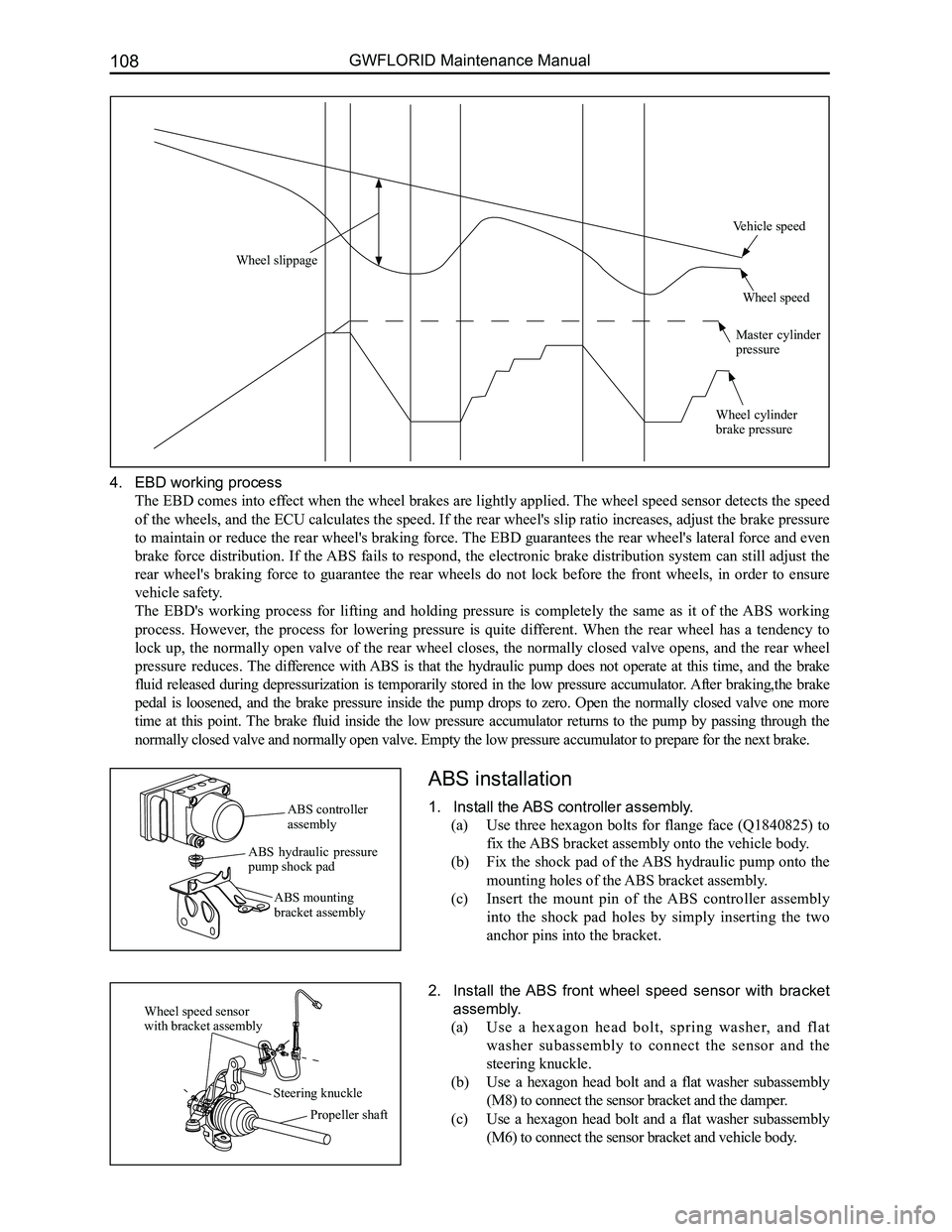
4. EBD working process
The EBD comes into effect when the wheel brakes are lightly applied. The wheel speed sensor detects the speed
of the wheels, and the ECU calculates the speed. If the rear wheel's slip ratio increases, adjust the brake pressure
to maintain or reduce the rear wheel's braking force. The EBD guarantees the rear wheel's lateral force and even
brake force distribution. If the ABS fails to respond, the electronic brake distribution system can still adjust the
rear wheel's braking force to guarantee the rear wheels do not lock before the front wheels, in order to ensure
vehicle safety.
The EBD's working process for lifting and holding pressure is completely the same as it of the ABS working
process. However, the process for lowering pressure is quite different. When the rear wheel has a tendency to
lock up, the normally open valve of the rear wheel closes, the normally closed valve opens, and the rear wheel
pressure reduces. The difference with ABS is that the hydraulic pump does not operate at this time, and the brake
fluid released during depressurization is temporarily stored in the low pressure accumulator. After braking,the brake
pedal is loosened, and the brake pressure inside the pump drops to zero. Open the normally closed valve one more
time at this point. The brake fluid inside the low pressure accumulator returns to the pump by passing through the
normally closed valve and normally open valve. Empty the low pressure ac\
cumulator to prepare for the next brake.
ABS installation
1. Install the ABS controller assembly.
(a) Use three hexagon bolts for flange face (Q1840825) to
fix the ABS bracket assembly onto the vehicle body.
(b) Fix the shock pad of the ABS hydraulic pump onto the
mounting holes of the ABS bracket assembly.
(c) Insert the mount pin of the ABS controller assembly
into the shock pad holes by simply inserting the two
anchor pins into the bracket.
2. Install the ABS front wheel speed sensor with bracket
assembly.
(a) Use a hexagon head bolt, spring washer, and flat
washer subassembly to connect the sensor and the
steering knuckle.
(b) Use a hexagon head bolt and a flat washer subassembly
(M8) to connect the sensor bracket and the damper.
(c) Use a hexagon head bolt and a flat washer subassembly
(M6) to connect the sensor bracket and vehicle body.
ABS controller assembly
ABS hydraulic pressure pump shock pad
ABS mounting bracket assembly
Wheel speed sensor with bracket assembly
Steering knuckle
Propeller shaft
Wheel slippage
Vehicle speed
Wheel speed
Master cylinder pressure
Wheel cylinder brake pressure
Page 116 of 281
Downloaded from www.Manualslib.com manuals search engine 109Brake System
3. Installing the ABS rear wheel speed sensor with brack-
et assembly.
Use three hexagon head bolts, spring washers, and flat
washer subassembly connecting pieces to connect the sensor
to the rear hub unit, rear twist beam, and vehicle body.
ABS General Problem Maintenance and Areas of Importance
Common problems and solutions
1. When braking, the ABS hydraulic pressure unit noise is overly loud.
When the ABS is working, the motor inside the hydraulic pressure unit is ceaselessly rotating. At this time the
driver can feel the brake pedal bouncing back. However, this bounce back feeling will be entirely different
depending on the speed and road condition. Also, when performing an actuator movement test, the sound of the
running motor may also be sensed. When the vehicle is being driven and the brake is off, the sound of the motor
running can still occasionally be heard. This is the ABS undergoing component inspection, not a malfunction.
If the ABS hydraulic pressure unit noise is irregular, a movement test can be initiated. Compare the noise to that
of normal vehicles to determine if ABS hydraulic pressure unit noise is abnormal.
2. Inlet and outlet solenoid valve failure.
Once the ignition switch is ON, the ABS control unit automatically initiates a self-check. If an inlet and outlet solenoid
valve short circuit or open circuit is found, it will record the failure, light up the fault light, and abort the operation. If using a
scanner to adjust the problem code, make sure to use the movement test t\
o confirm that the solenoid valve has a problem and
then replace the hydraulic pressure unit directly.
X431 data flow: While the ABS is functioning, the inlet and outlet solenoid valves rapidly change operating
conditions.
EVFL - Front inlet valve LHOff / On
AVFL - Front outlet valve LHOff / On
EVFR - Front outlet valve RHOff / On
AVFR - Rront outlet valve RHOff / On
EVRR - Rear inlet valve LHOff / On
AVRR - Rear outlet valve LHOff / On
EVRR - Rear inlet valve RHOff / On
AVRR - Rear outlet valve RHOff / On
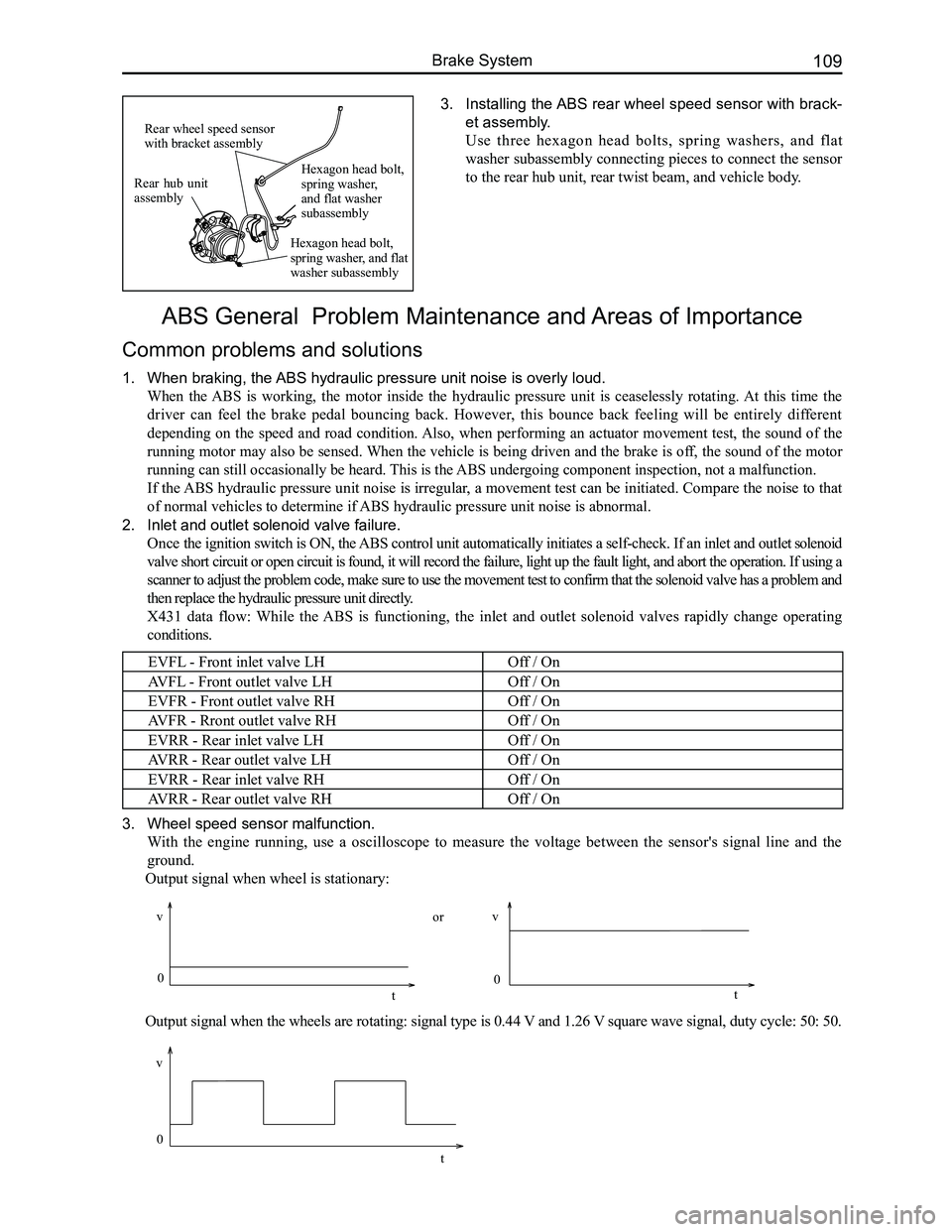
3. Wheel speed sensor malfunction.
With the engine running, use a oscilloscope to measure the voltage between the sensor's signal line and the
ground.
Output signal when wheel is stationary:
Output signal when the wheels are rotating: signal type is 0.44 V and 1.26 V square wave signal, duty cycle: 50: 50.
Rear hub unit assembly
Rear wheel speed sensor with bracket assembly
Hexagon head bolt, spring washer, and flat washer subassembly
Hexagon head bolt, spring washer, and flat washer subassembly
0
v
t
vv
0 0
tt
or
Page 117 of 281
Downloaded from www.Manualslib.com manuals search engine GWFLORID Maintenance Manual110
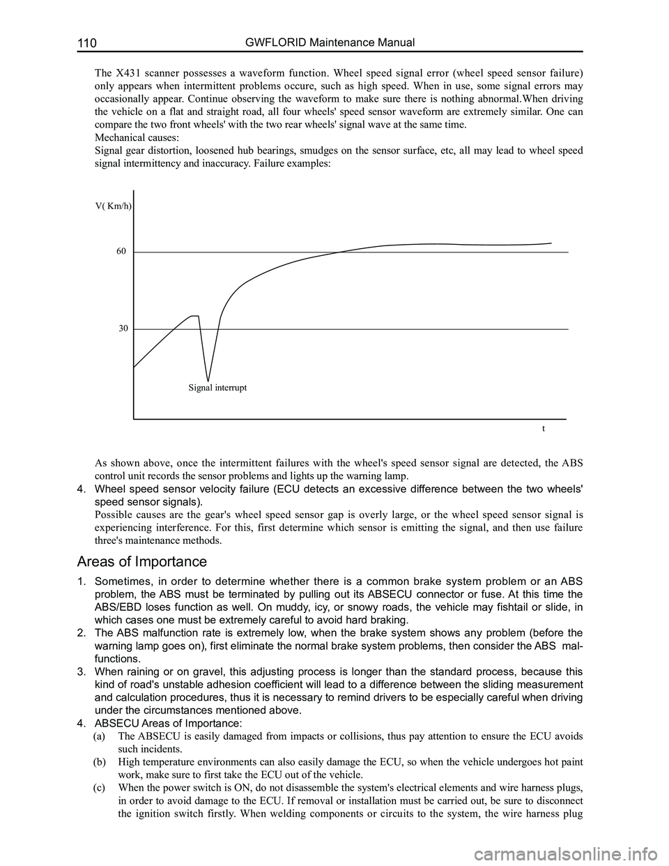
The X431 scanner possesses a waveform function. Wheel speed signal error (wheel speed sensor failure)
only appears when intermittent problems occure, such as high speed. When in use, some signal errors may
occasionally appear. Continue observing the waveform to make sure there is nothing abnormal.When driving
the vehicle on a flat and straight road, all four wheels' speed sensor waveform are extremely similar. One can
compare the two front wheels' with the two rear wheels' signal wave at t\
he same time.
Mechanical causes:
Signal gear distortion, loosened hub bearings, smudges on the sensor surface, etc, all may lead to wheel speed
signal intermittency and inaccuracy. Failure examples:
As shown above, once the intermittent failures with the wheel's speed sensor signal are detected, the ABS
control unit records the sensor problems and lights up the warning lamp.\
4. Wheel speed sensor velocity failure (ECU detects an excessive difference between the two wheels'
speed sensor signals).
Possible causes are the gear's wheel speed sensor gap is overly large, or the wheel speed sensor signal is
experiencing interference. For this, first determine which sensor is emitting the signal, and then use failure
three's maintenance methods.
Areas of Importance
1. Sometimes, in order to determine whether there is a common brake system problem or an ABS
problem, the ABS must be terminated by pulling out its ABSECU connector or fuse. At this time the
ABS/EBD loses function as well. On muddy, icy, or snowy roads, the vehicle may fishtail or slide, in
which cases one must be extremely careful to avoid hard braking.
2. The ABS malfunction rate is extremely low, when the brake system shows any problem (before the
warning lamp goes on), first eliminate the normal brake system problems, then consider the ABS mal-
functions.
3. When raining or on gravel, this adjusting process is longer than the standard process, because this
kind of road's unstable adhesion coefficient will lead to a difference between the sliding measurement
and calculation procedures, thus it is necessary to remind drivers to be especially careful when driving
under the circumstances mentioned above.
4. ABSECU Areas of Importance:
(a) The ABSECU is easily damaged from impacts or collisions, thus pay attention to ensure the ECU avoids
such incidents.
(b) High temperature environments can also easily damage the ECU, so when the vehicle undergoes hot paint
work, make sure to first take the ECU out of the vehicle.
(c) When the power switch is ON, do not disassemble the system's electrical elements and wire harness plugs,
in order to avoid damage to the ECU. If removal or installation must be carried out, be sure to disconnect
the ignition switch firstly. When welding components or circuits to the system, the wire harness plug
V( Km/h)
60
30
Signal interrupt
t
Page 118 of 281
Downloaded from www.Manualslib.com manuals search engine 111Brake System
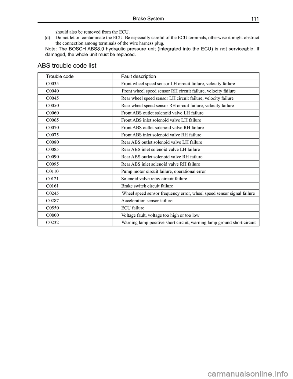
ABS trouble code list
Trouble codeFault description
C0035Front wheel speed sensor LH circuit failure, velocity failure
C0040Front wheel speed sensor RH circuit failure, velocity failure
C0045Rear wheel speed sensor LH circuit failure, velocity failure
C0050Rear wheel speed sensor RH circuit failure, velocity failure
C0060Front ABS outlet solenoid valve LH failure
C0065Front ABS inlet solenoid valve LH failure
C0070Front ABS outlet solenoid valve RH failure
C0075Front ABS inlet solenoid valve RH failure
C0080Rear ABS outlet solenoid valve LH failure
C0085Rear ABS inlet solenoid valve LH failure
C0090Rear ABS outlet solenoid valve RH failure
C0095Rear ABS inlet solenoid valve RH failure
C0110Pump motor circuit failure, operational error
C0121Solenoid valve relay circuit failure
C0161Brake switch circuit failure
C0245Wheel speed sensor frequency error, wheel speed sensor signal failure
C0287Acceleration sensor failure
C0550ECU failure
C0800Voltage fault, voltage too high or too low
C0232Warning lamp positive short circuit, warning lamp ground short circuit
should also be removed from the ECU.
(d) Do not let oil contaminate the ECU. Be especially careful of the ECU terminals, otherwise it might obstruct
the connection among terminals of the wire harness plug.
Note: The BOSCH ABS8.0 hydraulic pressure unit (integrated into the ECU) is not serviceable. If
damaged, the whole unit must be replaced.