2008 GREAT WALL FLORID wheel bolts
[x] Cancel search: wheel boltsPage 11 of 281

Downloaded from www.Manualslib.com manuals search engine GWFLORID Maintenance Manual4
Comprehensive Repair Instructions
1. Use the splasher, backing, and carpet to keep the vehicle
clean and to prevent damage.
2. W h i l e r e m o v i n g , m a r k a l l v e h i c l e c o m p o n e n t s o r
place all the components in proper order to make re-
assembling more convenient.
3. Disposable parts:
(a) Always use new parts to replace cotter pins, gaskets, O-
rings, and oil seals.
(b) Disposable parts will be marked with a "" in the
components schematics section.
4. Precoated components.
The precoated components include bolts and nuts which
have been coated with locking sealant in the factory.
(a) If the precoated part is tightened, loosened, or moved
for certain reason, it must be coated with prescriptive
sealant again.
(b) When reused, the original sealant should first be
cleaned and dried using compressed air. Afterwards,
use the required locking sealant to coat the bolts, nuts,
or threads.
(c) Precoated parts are marked with "" in the components
schematics section.
5. All rules regarding a bolt's tightening torque must be
seriously obeyed, and a torque wrench must be used.
6. Be careful when using a jack to raise and support the
vehicle. Make sure to jack up and support the vehicle
at proper locations.
(a) To ensure safety, chock up the wheels of the opposite
side if the place to be jacked up is either the front or
back of the vehicle.
(b) After lifting the vehicle, make absolutely sure to
support it with a bracket. It's extremely dangerous to
perform maintenance using merely a jack, even if to
finish the small matter quickly.
Torque wrench indication type
Torque wrench scale indication type
Hydraulic jackScissor type jack
Page 16 of 281

Downloaded from www.Manualslib.com manuals search engine 9Overview
General Repair Methods and Operations
1. If a jack is needed, please kindly comply to the safety procedures liste\
d below.
2. Park the vehicle on a flat surface, stablize the front and the back wheels using any fixed object or tool,
jack up the vehicle, support it with the chassis, and then start the mai\
ntenance.
3. Disconnect the battery's negative cable before maintenance, in order to reduce the possibility of
damaging and burning out the cable due to a short circuit.
4. Cover the vehicle body, seats, and floor to prevent them from being damaged and polluted.
5. Handle brake fluid and antifreeze fluid carefully, because it may damage the vehicle's surface paint
and its surroundings.
6. Using the proper tools or basic tools that have been recommended and are purchasable is very
important in guaranteeing an effective and reliable maintenance result.
7. Dispose the used dowel pins, gaskets, O-rings, oil seals, lock washers, and self-locking nuts. Prepare
new parts for installation. Normal functions are not guaranteed if these\
parts are reused.
8. Store the removed parts in order and in groups to make reassembly more c\
onvenient.
9. Store bolts and nuts separately, because their hardness levels and designs are different according to
the installation locations.
10. Clean parts before they are inspected or reassembled. In addition, parts that come in contact with
engine oil also need to be cleaned, as well as checked for blockage by u\
sing compressed air.
11. Before installation, use engine oil or grease to lubricate the rotating and sliding sides of the necessary
parts.
12. When necessary, use sealant on gaskets to avoid leakage.
13. Please carefully comply to all tightening torque specifications of b\
olts and nuts.
14. After maintenance, check to make sure whether the repairs were performed correctly and whether the
malfunctions have been fixed.
Vehicle Lifting/Lowering Procedures
When lifting the vehicle, the lifter must be placed at the indicated spots. Using these indicated spots
incorrrectly can lead to permanent deformation of the vehicle body. Many vehicle service stations
have autolifts that raise vehicles by supporting certain vehicle parts. If using other types of lifts, be
careful to prevent damages to the fuel tank, oil filler, or the base of the vehicle body.
Frame contact lifting device and basic hand jack
Floor arch jack
Lifting points (left/right) of central threshold
Page 81 of 281

Downloaded from www.Manualslib.com manuals search engine GWFLORID Maintenance Manual74
3. Remove the wheel speed sensor and the brake hose
Remove the wheel speed sensor's mounting bolts with a M10
sleeve to take off the wheel speed sensor. Remove the front
brake hose's mounting bolts with a M18 sleeve, and then
take off the brake hose.
Caution: When removing the brake hose, brake fluid
may flow out, catch the fluid with a container. Also,
b e c a u s e t h e b r a k e f l u i d i s c o r r o s i v e , p l e a s e p a y
attention to personal protection.
4. Remove the cotter pins and lock nuts of the steering tie
rod and the lower swing arm
Because the ball stud and steering knuckle act in conjunction
with the tapered bore, they can not yet be removed after re-
moving the nuts. Pound the steering knuckle arm (unfinished
surface) with a hammer. Positions are shown on the left.
Shake to loosen.
Caution:
1. To avoid separating the ball studs, do not pound the
tie rod and the lower swing arm with a hammer.
2. To avoid damaging the thread, do not hammer the
ball stud's head.
Front brake hose mounting bolt
Wheel speed sensor mounting bolts
Lightly hammer here
Page 82 of 281

Downloaded from www.Manualslib.com manuals search engine 75Suspension System
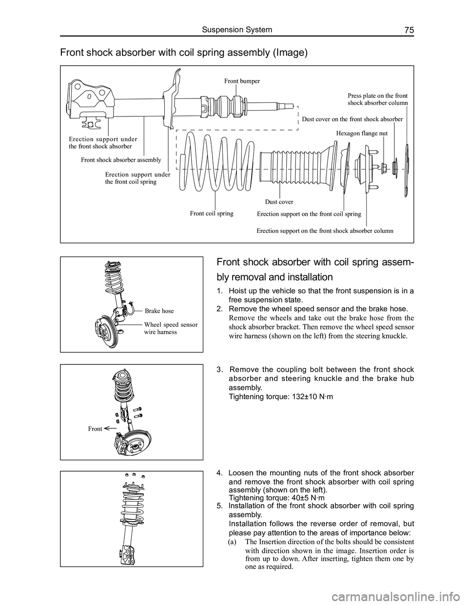
Front shock absorber with coil spring assembly (Image)
Front shock absorber with coil spring assem-
bly removal and installation
1. Hoist up the vehicle so that the front suspension is in a
free suspension state.
2. Remove the wheel speed sensor and the brake hose.
Remove the wheels and take out the brake hose from the
shock absorber bracket. Then remove the wheel speed sensor
wire harness (shown on the left) from the steering knuckle.
3. Remove the coupling bolt between the front shock
absorber and steering knuckle and the brake hub
assembly.
Tightening torque: 132±10 N·m
4. Loosen the mounting nuts of the front shock absorber
and remove the front shock absorber with coil spring
assembly (shown on the left).
Tightening torque: 40±5 N·m
5. Installation of the front shock absorber with coil spring
assembly.
Installation follows the reverse order of removal, but
please pay attention to the areas of importance below:
(a) The Insertion direction of the bolts should be consistent
with direction shown in the image. Insertion order is
from up to down. After inserting, tighten them one by
one as required.
Front
Brake hose
Wheel speed sensor wire harness
E r e c t i o n s u p p o r t u n d e r the front shock absorber
Front shock absorber assembly
Erection support under the front coil spring
Front coil spring
Dust cover
Erection support on the front shock absorber column
Hexagon flange nut
Press plate on the front shock absorber column
Dust cover on the front shock absorber
Erection support on the front coil spring
Front bumper
Page 85 of 281

Downloaded from www.Manualslib.com manuals search engine GWFLORID Maintenance Manual78
Remark: When removing the subframe's front mounting bolt,
an extension bar should be inserted through the lower swing
arm's hole. Positions shown on the left.
5. Subframe installation.
Installation follows the reverse removal steps.
Caution: Fix the position of the subframe with the
position pin, to avoid influencing the four wheels'
positioning. Location hole is shown on the left: a total
of two, one on the left and one on the right.
Stabilizer bar removal and installation
1. Remove the hanger rod.
Use a M10 open-end wrench to lock the sliding side of the
hanger rod (slightly higher than center position), screw off
the hanger rod lock nuts, and remove the hanger rod.
Caution: These are non-metal insert lock nuts, and
cannot be reused. So please replace them with new
ones after removal.
2. Remove the stabilizer bar arm.
Remove the stabilizer bar bracket mounting bolts Q1400830
(d2=13.5), and take down the bracket and bushing. As shown
on the left: There are four bolts, two on the left and two on
the right.
Tightening torque: 23±3 N·m
3. Stabilizer bar installation.
Install it by reversing the removal steps, but please pay
attention to the areas of importance below:
(a) During removal, please remember the installation order
of each of the hanger rod's components, so as to avoid
improper installation.
Insert extension bar through this hole
This is the subframe location hole
Q1400830
WasherBushingHanger rod
Shaft sleeve
BushingWasher
Page 115 of 281

Downloaded from www.Manualslib.com manuals search engine GWFLORID Maintenance Manual108
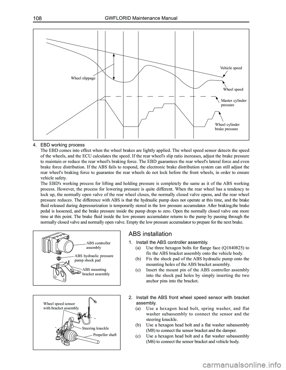
4. EBD working process
The EBD comes into effect when the wheel brakes are lightly applied. The wheel speed sensor detects the speed
of the wheels, and the ECU calculates the speed. If the rear wheel's slip ratio increases, adjust the brake pressure
to maintain or reduce the rear wheel's braking force. The EBD guarantees the rear wheel's lateral force and even
brake force distribution. If the ABS fails to respond, the electronic brake distribution system can still adjust the
rear wheel's braking force to guarantee the rear wheels do not lock before the front wheels, in order to ensure
vehicle safety.
The EBD's working process for lifting and holding pressure is completely the same as it of the ABS working
process. However, the process for lowering pressure is quite different. When the rear wheel has a tendency to
lock up, the normally open valve of the rear wheel closes, the normally closed valve opens, and the rear wheel
pressure reduces. The difference with ABS is that the hydraulic pump does not operate at this time, and the brake
fluid released during depressurization is temporarily stored in the low pressure accumulator. After braking,the brake
pedal is loosened, and the brake pressure inside the pump drops to zero. Open the normally closed valve one more
time at this point. The brake fluid inside the low pressure accumulator returns to the pump by passing through the
normally closed valve and normally open valve. Empty the low pressure ac\
cumulator to prepare for the next brake.
ABS installation
1. Install the ABS controller assembly.
(a) Use three hexagon bolts for flange face (Q1840825) to
fix the ABS bracket assembly onto the vehicle body.
(b) Fix the shock pad of the ABS hydraulic pump onto the
mounting holes of the ABS bracket assembly.
(c) Insert the mount pin of the ABS controller assembly
into the shock pad holes by simply inserting the two
anchor pins into the bracket.
2. Install the ABS front wheel speed sensor with bracket
assembly.
(a) Use a hexagon head bolt, spring washer, and flat
washer subassembly to connect the sensor and the
steering knuckle.
(b) Use a hexagon head bolt and a flat washer subassembly
(M8) to connect the sensor bracket and the damper.
(c) Use a hexagon head bolt and a flat washer subassembly
(M6) to connect the sensor bracket and vehicle body.
ABS controller assembly
ABS hydraulic pressure pump shock pad
ABS mounting bracket assembly
Wheel speed sensor with bracket assembly
Steering knuckle
Propeller shaft
Wheel slippage
Vehicle speed
Wheel speed
Master cylinder pressure
Wheel cylinder brake pressure
Page 116 of 281

Downloaded from www.Manualslib.com manuals search engine 109Brake System
3. Installing the ABS rear wheel speed sensor with brack-
et assembly.
Use three hexagon head bolts, spring washers, and flat
washer subassembly connecting pieces to connect the sensor
to the rear hub unit, rear twist beam, and vehicle body.
ABS General Problem Maintenance and Areas of Importance
Common problems and solutions
1. When braking, the ABS hydraulic pressure unit noise is overly loud.
When the ABS is working, the motor inside the hydraulic pressure unit is ceaselessly rotating. At this time the
driver can feel the brake pedal bouncing back. However, this bounce back feeling will be entirely different
depending on the speed and road condition. Also, when performing an actuator movement test, the sound of the
running motor may also be sensed. When the vehicle is being driven and the brake is off, the sound of the motor
running can still occasionally be heard. This is the ABS undergoing component inspection, not a malfunction.
If the ABS hydraulic pressure unit noise is irregular, a movement test can be initiated. Compare the noise to that
of normal vehicles to determine if ABS hydraulic pressure unit noise is abnormal.
2. Inlet and outlet solenoid valve failure.
Once the ignition switch is ON, the ABS control unit automatically initiates a self-check. If an inlet and outlet solenoid
valve short circuit or open circuit is found, it will record the failure, light up the fault light, and abort the operation. If using a
scanner to adjust the problem code, make sure to use the movement test t\
o confirm that the solenoid valve has a problem and
then replace the hydraulic pressure unit directly.
X431 data flow: While the ABS is functioning, the inlet and outlet solenoid valves rapidly change operating
conditions.
EVFL - Front inlet valve LHOff / On
AVFL - Front outlet valve LHOff / On
EVFR - Front outlet valve RHOff / On
AVFR - Rront outlet valve RHOff / On
EVRR - Rear inlet valve LHOff / On
AVRR - Rear outlet valve LHOff / On
EVRR - Rear inlet valve RHOff / On
AVRR - Rear outlet valve RHOff / On
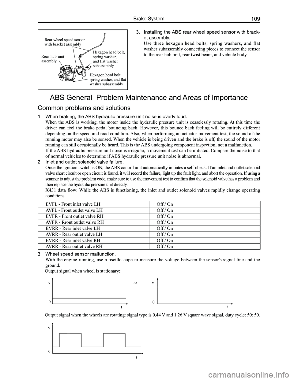
3. Wheel speed sensor malfunction.
With the engine running, use a oscilloscope to measure the voltage between the sensor's signal line and the
ground.
Output signal when wheel is stationary:
Output signal when the wheels are rotating: signal type is 0.44 V and 1.26 V square wave signal, duty cycle: 50: 50.
Rear hub unit assembly
Rear wheel speed sensor with bracket assembly
Hexagon head bolt, spring washer, and flat washer subassembly
Hexagon head bolt, spring washer, and flat washer subassembly
0
v
t
vv
0 0
tt
or
Page 121 of 281

Downloaded from www.Manualslib.com manuals search engine GWFLORID Maintenance Manual114
(d) Measure the front hub bearing's starting torque.
Put the SST on the wheel bolts which are at the symmetric
locations. Put a dial torque wrench on the SST to slowly
rotate the flange assembly (45°/4s), requiring a starting
torque range of 0.1-0.3 N·m.
If the bearing rotation is not flexible, the front hub flange
plate surface movement inaccurate, or front hub bearing
starting torque is too much. The assembly must be replaced.
Steering knuckle's front hub bearing and
front hub flange assembly
1. Removal and inspection of front hub flange assembly.
(a) Use SST like a hand held travel hammer to repeatedly
hammer off the front hub flange assembly from the
steering knuckle and front hub bearing. Remove the
front hub with bearing's inner ring.
(b) Remove the bearing's inner ring on the front hub.
Use SST to remove the bearing's inner ring.
SST
SST
Bearing inner ring
SST
(c) Use dye penetrant to inspect the front hub flange for
cracks, which should be replaced if found.
(d) If one would like to continue using the front hub flange
assembly, first inspect the dimensions for the mounting
area of the bearing for inaccurate dimensions. If
oversized, replace.
Measurement range: Φ38+0.025 +0.009 mm
2. Remove the steering knuckle's front hub bearing.
3. Remove the snap ring for hole 72.
Use a bent nose retaining ring caliper for holes to remove the
snap ring for hole 72.