2008 GREAT WALL FLORID sensor
[x] Cancel search: sensorPage 183 of 281

Downloaded from www.Manualslib.com manuals search engine GWFLORID Maintenance Manual176
Auxiliary system
To diagnostic port
To ECU 29#
To ECU 71#
Theft deterrent indicatorReverse lamp switch
Left reverse lamp
Right reverse lamp Detector No. 1
Detector No. 2
Detector No. 3
Detector No. 4
Theft deterrent coil
Connected theft deterrent ECU Connected diagnostic port Detector No. 1
Detector No. 2Detector No. 3 Detector No. 4
Connected theft deterrent indicator
Connected reverse sensor controller Connected reverse sensor buzzerBuzzer
Ignition switch IG1
Theft deterrent controller
Reverse sensor controller
Page 184 of 281

Downloaded from www.Manualslib.com manuals search engine 177Electrical Accessories
Reverse Sensor ................................................................178
Combination Meter ...........................................................180
Central Door Lock.............................................................181
Power Windows ................................................................184
Immobilizer System ..........................................................186
CD Player ........................................................................\
.193
DVD Player .......................................................................195
Electrical Accessories
Page 185 of 281

Downloaded from www.Manualslib.com manuals search engine GWFLORID Maintenance Manual178
Reverse Sensor
Reverse sensor operation (ultrasonic wave distance-measurement)
Sound is a kind of wave. Sound frequency that can be heard by human beings range from 20 Hz to 20 KHz.
Those that exceed 20 KHz are called ultrasonic waves. Since an ultrasonic wave is also a kind of sound, its
velocity in the air also equals the sound velocity of 340 m/s. Part of the ultrasonic wave will rebound when it
encounters an obstacle. So the distance between the sound source and the obstacle can be calculated according
to the sonic speed and the time difference between the emission of sound and the receipt of sound.
Reverse sensor system composition
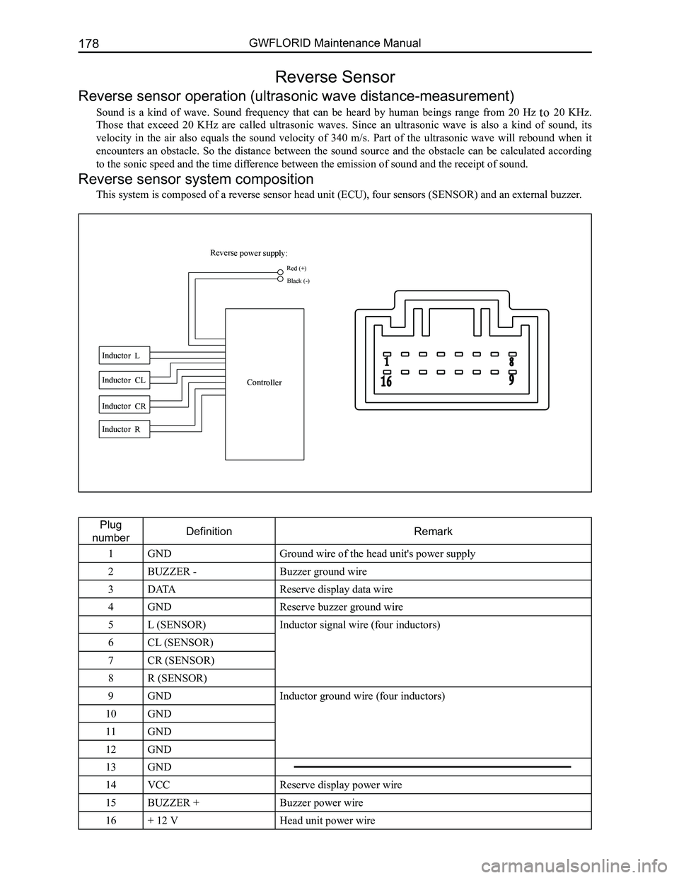
This system is composed of a reverse sensor head unit (ECU), four sensors (SENSOR) and an external buzzer.
Plug
numberDefinitionRemark
1GNDGround wire of the head unit's power supply
2BUZZER -Buzzer ground wire
3DATAReserve display data wire
4GNDReserve buzzer ground wire
5L (SENSOR)Inductor signal wire (four inductors)
6CL (SENSOR)
7CR (SENSOR)
8R (SENSOR)
9GNDInductor ground wire (four inductors)
10GND
11GND
12GND
13GND
14VCCReserve display power wire
15BUZZER +Buzzer power wire
16+ 12 VHead unit power wire
Reverse power supply:
Inductor L Inductor CL
Inductor CR Inductor R Controller
Red (+)
Black (-)
Page 186 of 281

Downloaded from www.Manualslib.com manuals search engine 179Electrical Accessories
Functional description and display program
1. This system will be activated within the first second after engaging the reverse gear. There will be two
beeps indicating the system is working properly.
2. After the self-check, it will start its normal detection mode. The relationship between the obstacle
distance and the alarm frequency is as follows:
A Zone: When it is a long sounding alarm, the obstacle is within the distance of (0-40±4) cm.
B Zone: When the alarm frequency is an 8 Hz continuous sound, the obstacle is within the distance of
(40±4-90±4) cm.
C Zone: When the alarm frequency is a 4 Hz intermittent sound, the obstacle is within the distance of (90±4-
150±4) cm.
Areas of importance
1. When placed near a car equipped with the same system or a similar system (having been activated)
offered by other suppliers, though this system may receive interference, i\
t can still operate normally.
2. When the relative rate of travel between the obstacle and the car is lower than 1 m/s, this system will
operate as normal. When reverse speed is accelerated, the sensing accuracy of the reverse system
may decrease. A low speed of 6 km/h is suggested.
3. When it is a long sounding alarm, please stop the car at once, because there may be an obstacle
within 40cm.
4. The inductor precision level is high. It will be very difficult to return it to normal after opening the inner
portion.
5. The reflected signal may not be received due to the location, angle, size, or material of the object.
Furthermore, the reflected signal in a complex environment may not be ac\
curate.
System malfunction causes and solutions
1. A lack of power or a low supply voltage may lead to the abnormal operation of the reverse sensor
system. Under such circumstances, check whether the supply battery voltage is normal, or whether
the ignition switch connector and other connections are accurately place\
d.
2. If the power supply is on, irregular system operation may be caused by the incorrect position of the
socket. Under such circumstances, correctly re-place all the sockets.
3. A long sounding alarm from the buzzer may be caused by the inductor coming off, incorrect installa-
tion, damage to the inductor, or detecting the car or ground. Under such circumstances, please repair
or replace the sensor.
4. Incorrect indication of an obstacle's distance may be caused by abnormal battery voltage, inaccurate
socket positioning, or inductor connection damage. At this time, check whether the battery voltage
is normal, and whether the inductor connection is connected to the exhaust pipe and muffler. It is
suggested that the system be turned off and all the sockets be correctly placed.
Reverse sensor system parameters
Rated operation voltageDC 12 V
Operation voltage rangeDC (9.6-16) V
Operation temperature range-30-80 oC
Storage temperature range-40-85 oC
Power consumption< 2 W
Detect segment3 segments: 150-90-40 cm
Maximum sensing distance150±4 cm
Effective distance(15±4) cm- (150±4) cm
Detect modeUltrasonic wave
C Zone
(4 Hz intermittent sound)
40±4 cm 90±4 cm 150±4 cm
A Zone
(long alarm)
B Zone
(8 Hz continuous sound)
Page 225 of 281

Downloaded from www.Manualslib.com manuals search engine GWFLORID Maintenance Manual218
detection but also during the diagnostic detection cycle. However, if a short circuit on the power supply causes
a malfunction, and the low-end transistor is opened while malfunctioned, the low-end transistor can only be
detected when starting up detection, as to avoid faulty execution.
(b) Ignition voltage is provided by a pressure increase converter.
(c) Acceleration sensor performs self-detection when starting up detection.
(d) Allowed offset range of the acceleration sensor during a diagnostic cycle.
(e) Microcontroller includes AD converter, ROM, RAM, etc.
(f) Security sensor status.
Caution: There is a short-circuiting bar inside the squib circuit connector. When the connector is not
connected, the short circuit happens between the squib circuit's terminal (+) and terminal (-), as to
avoid faulty deployment caused by static electricity. When the connector is bad and the short-circuiting
bar is connected, the fault symptom may not be eliminated.
4. Clear the trouble code
When the X-431 diagnostic instrument receives the "Clear the trouble code" order sent through the serial inter-
face, the trouble code inside the ECU will be cleared. However, if an internal trouble code is recorded or has a
collision record, it will not carry out this order.
(a) Malfunction status display.
When the working voltage is supplied to the SRS-ECU through a battery, the SRS-ECU will light the warning
lamp to inspect the light bulbs. During the initialization stage, the warning lamp will remain on for 6-7 s, and
in order to inform the driver that the system has a malfunction, the warning lamp will continue to remain on
after the working voltage is supplied. If the history trouble code’s quantity is less than 16, the warning lamp
will remain lit for 6-7 s after turning the ignition on and then turn off automatically. If the history trouble code’s
quantity is 16 and the current malfunction appears, it will be recorded and the first history malfunction record
will be automatically removed.
(b) Malfunction indicator.
When the system has malfunctioned, the warning lamp will be always on.
A displayed or history malfunction can only be reset by service personnel. A SRS-ECU internal malfunction or
malfunction’s "collision record" cannot be reset. In this situation, the SRS-ECU mus\
t be replaced.
(c) Microcontroller - independent warning lamp is lit.
The controller has a self-diagnosis function. If the inner controller malfunctions, the warning lamp will always
be on.
(d) If the airbag warning lamp is always on, please inspect it according to the following steps.
The first step of inspecting any of the malfunctions is to detect the malfunction’s position with a scanner. Then
carry out the inspection using the corresponding part’s inspection method. If the scanning result is an internal
malfunction or having to do with airbag execution, the SRS-ECU can be di\
rectly replaced.