Page 83 of 419
Cooling - Radiator with electronic fan assemblyRadiator with electronic fan assemblyReplacement1. Discharge coolant (see Page 73).
2. Disassemble radiator water inlet hose [64000062].
3. Disassemble radiator water outlet hose [64000063].
4. Disassemble No.1 oil cooler inlet pipe (auto gear).
5. Disassemble No.1 oil cooler outlet pipe (auto gear).
6. Disassemble fixing clips of 2 wire harnesses from fan cover.
7. Remove mounting bracket assembly on radiator [64000058].
8. Remove radiator together with electronic fan assembly [64000057].
9. Remove electronic fan together with fan cover assembly [64000060].(a) Screw off fixed nuts connecting electronic fan together with fan cover assembly with radiator.
(b) Uncouple fan motor joint.
(c) Remove 2 bolts of fan.
(d) Remove fan motor at the same time.10. Replace and install as sequences opposite to the above.
11. Refill engine coolant (see Page 73).
12. Check there is leakage with coolant (see Page 66).
72
Page 84 of 419

CoolantReplacement1. Discharge engine coolant.Warning: when the temperature of engine and radiator is high, do not remove radiator cap to
avoid being scalded, because coolant and steam will spurt under high pressure.
(a) Remove radiator cap.
(b) Open radiator drain valve and engine drain valve.Cooling - Coolant2. Refill engine coolant.(a) Lock 2 drain valves and pour coolant into radiator until it is full.
Hints:Press radiator water inlet hose and outlet hose with hands several times.If coolant level is too low, please refill coolant again.
(b) Screw down radiator cap.
(c) Pour coolant into expansion tank until the level is up to “FULL” mark line.
(d) Run engine with vehicle warning up until thermostat valve is opened.
Hint:During vehicle warning up, press radiator water inlet hose and outlet hose with hands
several times.
(e) Engine flames out until coolant temperature falls to “cold”. Then open radiator cap and check coolant
level.
(f) If coolant level is too low, please perform the above steps again.
(g) If coolant level is not too low, please adjust expansion tank coolant level.3. Check there is leakage with coolant.(a) Refill engine coolant to radiator, and install radiator cap tester.
(b) Pressurize radiator to 118kPa, and check there is leakage.73Engine drain valve
Radiator drain valve Radiator cap
Drain pipe
Page 85 of 419

LubricationLubricating systemOn-vehicle inspection1. Check oil level.During engine warming up and after it flames out for 5 minutes, check oil level, and the level should
be between two marks on oil dipstick at the moment.If oil level is too low, check there is leakage, and
refill oil up to upper mark on oil dipstick.
Note: oil level should not be above upper mark on oil
dipstick.2. Check oil quality.(a) Check there is deterioration, water penetration, color
change or thinning with oil.
(b) If oil quality becomes poor, please replace with new oil.
Hint: oil grades: API, SH, SJ, SG grade oil or ILSAC
multigrade oil. Recommended viscosity is
shown as below.
The temperature increases from left to right.3. Remove oil pressure alerter assembly.(a) Uncouple oil pressure alerter joint.
(b) Install oil pressure alerter with special tool.4. Install oil pressure gauge.Install oil pressure gauge.5. Warm up vehicle.
6. Check oil pressure.Oil pressure:7. Install oil pressure alerter.(a) Coat adhesive on 2nd or 3rd circle thread of oil pressure
alerter.
Adhesive: anaerobic pipe thread sealing adhesive
1545 (Kesaixin 1545).
(b) Install oil pressure alerter with special tool.
Torque: m
(c) Connect oil pressure alerter joint.8. Start engine and check there is leakage.Lubrication - lubricating systemRecommended viscosity (SAE)
Oil pressure alerter
Oil pressure gauge
Adhesive74Temperature range in forecasting next
oil replacement
Page 86 of 419

Oil filter assemblyReplacementWarning:Long-term or repeat contacting mineral oil will cause decomposing of natural fat on skin, which
will result in dry and sensitive skin and skin rankling. Used oil has potential harm and may cause
carcinoma cutis.When replacing engine oil, always wear protective clothes and gloves to avoid waste oil
penetrating, and reduce the frequency and time of skin contacting waster oil, and clean with
soapy water or clean water not with gasoline, thinner or solvent if skin contacts waste oil.To protect environment, waste oil and oil filter must be abandoned at named place.1. Remove engine right bottom shield.
2. Discharge engine oil.
3. Remove oil filter assembly [4G18-1012100].Remove oil filter with special tool.4. Install oil filter assembly.(a) Check and clean oil filter junction plane.
(b) Coat oil seal of new oil filter with clean oil.
(c) Tighten oil filter with hands to the extent that oil seal
just touches fixing base.
(d) Tighten oil filter for another 3/4 circle with special tool.5. Install oil drain plug [4G18-1009101].Clean oil drain plug, and install it back after replacing oil drain plug gasket.
Torque: 6. Refill engine oil.
7. Check there is oil leakage.Lubrication - Oil filter assemblySpecial tool75Special tool 3/4 circle
Page 88 of 419

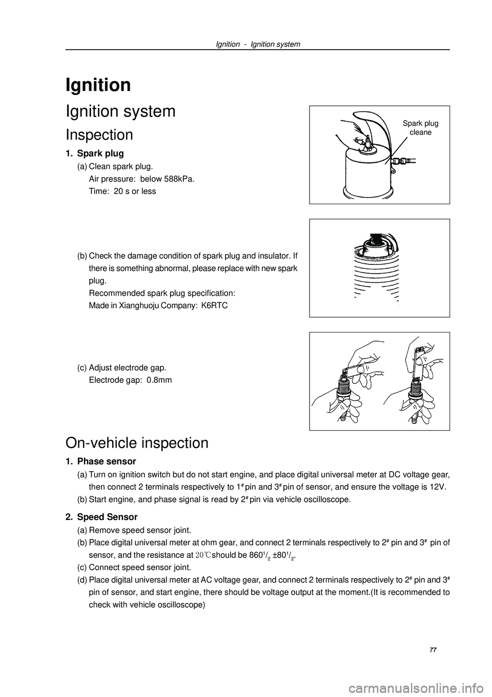
Ignition - Ignition systemSpark plug
cleaneOn-vehicle inspection1. Phase sensor(a) Turn on ignition switch but do not start engine, and place digital universal meter at DC voltage gear,
then connect 2 terminals respectively to 1# pin and 3# pin of sensor, and ensure the voltage is 12V.
(b) Start engine, and phase signal is read by 2# pin via vehicle oscilloscope.2. Speed Sensor(a) Remove speed sensor joint.
(b) Place digital universal meter at ohm gear, and connect 2 terminals respectively to 2# pin and 3# pin of
sensor, and the resistance at should be 8601/2 ±801/2.
(c) Connect speed sensor joint.
(d) Place digital universal meter at AC voltage gear, and connect 2 terminals respectively to 2# pin and 3#pin of sensor, and start engine, there should be voltage output at the moment.(It is recommended to
check with vehicle oscilloscope)IgnitionIgnition systemInspection1. Spark plug(a) Clean spark plug.
Air pressure: below 588kPa.
Time: 20 s or less
(b) Check the damage condition of spark plug and insulator. If
there is something abnormal, please replace with new spark
plug.
Recommended spark plug specification:
Made in Xianghuoju Company: K6RTC
(c) Adjust electrode gap.
Electrode gap: 0.8mm77
Page 89 of 419

Ignition - Ignition system3. Inspection of ignition coil (including igniter) and spark test(a) Check DTC.
Note: if there is display with DTC, perform trouble shooting according to DTC procedure.
(b) Check there is spark.
(1) Remove ignition coil (including igniter).
(2) Remove spark plug with 16mm spark plug sleeve.
(3) Install spark plug to each ignition coil (including igniter), and connect ignition coil joint.
(4) Uncouple joints of 4 injection nozzles.
(5) Earth spark plug.
(6) Check spark with engine running.
Notes:Be sure to earth spark plug during checking. When there is falling or collision with ignition coil,please replace with a new oneRunning engine time for each time should not be more than 2 seconds.
If there is no spark, please perform test as the following steps.
(c) Install spark plug with 16mm spark plug sleeve.
Torque: (d) Install ignition coil and igniter.
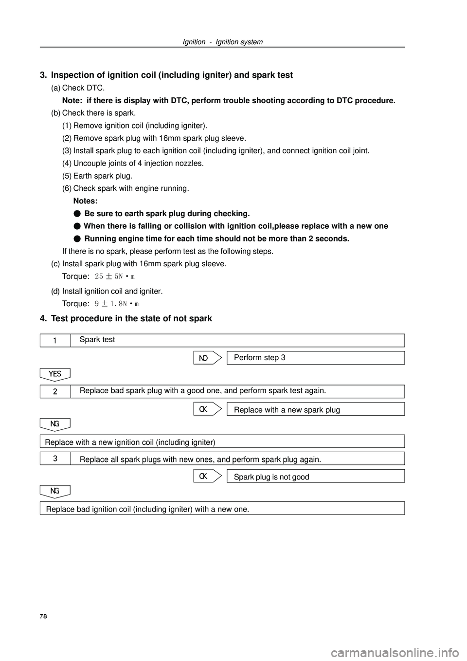
Torque: 4. Test procedure in the state of not spark
78Perform step 3Spark testReplace with a new spark plugReplace bad spark plug with a good one, and perform spark test again.Spark plug is not goodReplace all spark plugs with new ones, and perform spark plug again.Replace with a new ignition coil (including igniter)Replace bad ignition coil (including igniter) with a new one.
Page 92 of 419
Starting and charging - Charging systemCharging systemPrecautions1. Check positive and negative wire of battery is con-
nected correctly.
2. When performing quick charge to battery, please
uncouple battery wire.
3. Do not test with high-pressure insulation resistance
tester.
4. do not uncouple battery wire during engine running.
81
Page 93 of 419

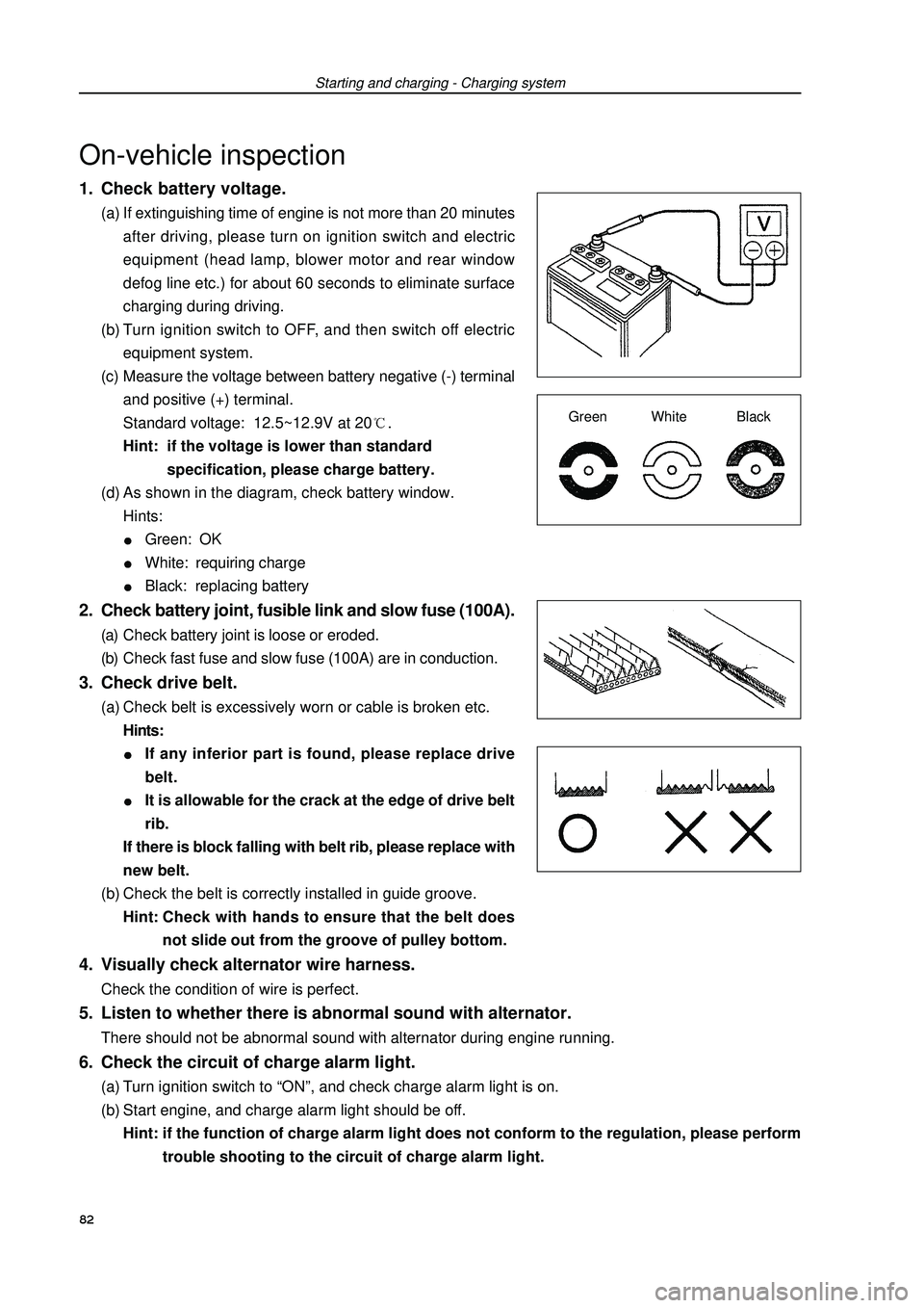
1. Check battery voltage.(a) If extinguishing time of engine is not more than 20 minutes
after driving, please turn on ignition switch and electric
equipment (head lamp, blower motor and rear window
defog line etc.) for about 60 seconds to eliminate surface
charging during driving.
(b) Turn ignition switch to OFF, and then switch off electric
equipment system.
(c) Measure the voltage between battery negative (-) terminal
and positive (+) terminal.
Standard voltage: 12.5~12.9V at 20.
Hint: if the voltage is lower than standard
specification, please charge battery.
(d) As shown in the diagram, check battery window.
Hints:Green: OKWhite: requiring chargeBlack: replacing battery2. Check battery joint, fusible link and slow fuse (100A).(a) Check battery joint is loose or eroded.
(b) Check fast fuse and slow fuse (100A) are in conduction.3. Check drive belt.(a) Check belt is excessively worn or cable is broken etc.
Hints:If any inferior part is found, please replace drive
belt.It is allowable for the crack at the edge of drive belt
rib.
If there is block falling with belt rib, please replace with
new belt.
(b) Check the belt is correctly installed in guide groove.
Hint:Check with hands to ensure that the belt does
not slide out from the groove of pulley bottom.4. Visually check alternator wire harness.Check the condition of wire is perfect.Starting and charging - Charging systemOn-vehicle inspectionGreen White Black5. Listen to whether there is abnormal sound with alternator.There should not be abnormal sound with alternator during engine running.6. Check the circuit of charge alarm light.(a) Turn ignition switch to “ON”, and check charge alarm light is on.
(b) Start engine, and charge alarm light should be off.
Hint: if the function of charge alarm light does not conform to the regulation, please perform
trouble shooting to the circuit of charge alarm light.82