2008 GEELY FC light
[x] Cancel search: lightPage 9 of 419

Change..........................................................
234
Condenser Assembly...........................................
236
Inspection on the automobile.......................
236
Overhaul........................................................
236
Supplemental restraint system
Note....................................................................
239
Malfunction treatment.........................................
244
Repair.................................................................
247
Inspection...........................................................
249
Remove malfunction...........................................
251
Malfunction table............................................
251
Diagnosis of impacted automobile.................
260
Disassemble and assemble...............................
261
Electronic control unit of safety airbag (ECU)..
261
Safety airbag assembly at the side of driver..
261
Safety airbag assemble at the side of passenger....263
Scrap treatment for safety airbag..................
264
Safety belt
Safety belt..........................................................
270
Note...............................................................
270
Treatment.......................................................
270
Subassembly.................................................
273
Change..........................................................
274
Rear safety belt..................................................
275
Subassembly.................................................
275
Change..........................................................
277
Light
Light System.......................................................
279
Notes..............................................................
279
The phenomena table....................................
279
Inspect the car...............................................
281
Inspect...........................................................
283
Front combination light (LH)..............................
286
Subassembly................................................
286
Change..........................................................
287Adjustments..................................................
287
Front fog light.....................................................
289
Components.................................................
289
Change..........................................................
290
Adjustment....................................................
290
Side turning light................................................
291
Components.................................................
291
Rear combination light (LH)..............................
292
Components.................................................
292
Change..........................................................
293
Rear fog light......................................................
294
Components.................................................
294
Change..........................................................
295
Number plate light.............................................
296
Change..........................................................
296
High brake light assembly.................................
297
Change..........................................................
297
Left combination switch.....................................
298
Change..........................................................
298
Wiper and cleaner
Wiper and cleaner system.................................
299
Malfunction phenomena table......................
299
Inspect the car...............................................
299
Inspect...........................................................
300
Right combination switch.................................
302
Change..........................................................
302
Wiper motor.......................................................
303
Change..........................................................
303
Wiper..................................................................
305
Change..........................................................
305
Cleaner nozzle...................................................
306
Adjustments..................................................
306
Audio system
Audio system.....................................................
307
Notes.............................................................
307
Radio assembly.................................................
308
Page 11 of 419

Engine cover/automobile door
Engine cover......................................................
366
Adjustment.....................................................
366
Front automobile door........................................
367
Subassembly.................................................
367
Overhaul........................................................
369
Adjustment.....................................................
372
Rear automobile door.......................................
373
Overhaul........................................................
373
Adjustment....................................................
375
Trunk cover.........................................................
377
Adjustment....................................................
377
Torsion spring of trunk cover.............................
378
Change..........................................................
378
Exterior/inner trim board
Front bumper....................................................
379
Subassembly................................................
379
Change..........................................................
380
Rear bumper......................................................
381
Subassembly................................................
381
Change..........................................................
382
Name plate........................................................
383
Change..........................................................
383
Exterior seal tape of left front door glass (LH)...
384
Change..........................................................
384
Exterior seal tape of left rear door glass...........
385
Change..........................................................
385
Light fender........................................................
386
Change..........................................................
386
Top left trim tape.................................................
387
Replacement.................................................
387
Left lower fender of automobile body (LH)........
388
Subassembly................................................
388
Change..........................................................
389
Inner trim board of top........................................
390
Change..........................................................
390Automobile control system
Ignition switch and anti-versa lock key warning switch.394
Malfunction phenomenon table.....................
394
Inspection......................................................
394
Electrical schematic diagram..............................
395
Page 12 of 419

Brief introduction on Geely model “FC”Basic parametersTable 1 Complete vehicle basic parametersUnit
Item nameNumber
Dimension parametersOverall
dimension
Wheel trackLength
Width
Height
Front wheel
Rear wheel
Wheel base
Front suspension
Rear suspensionPassenger numberPersonParameters±15±15±20±10±10±30±30Left lamp
Right lamp
Left lamp
Right lampLeft and
right
inclination
Down
inclinationComplete vehicle herb massMax. total massFront axle
Rear axle
Front axle
Rear axle
Weight distributionNo
load
Full
loadMin. turning diameter
Min. gound clearance
Approach angle (full load) Departure angle (full load)Front wheel camber
Kingpin inclination angle
caster angleConvergence of front wheelsRear wheel camberConvergence of rear wheelsLeft wheel: inside/outside
Right wheel:inside/outside CanderaBrief introduction on Geely model “FC” Basic parameters
Mass parameters
Traverse ability
Front wheel alignment
parameters
Rear wheel
alignment
parameters Front wheel
steering
wheel
Head lamp light
High beam
optical axisLuminous intensity of
high beam of head lamp1
Page 16 of 419

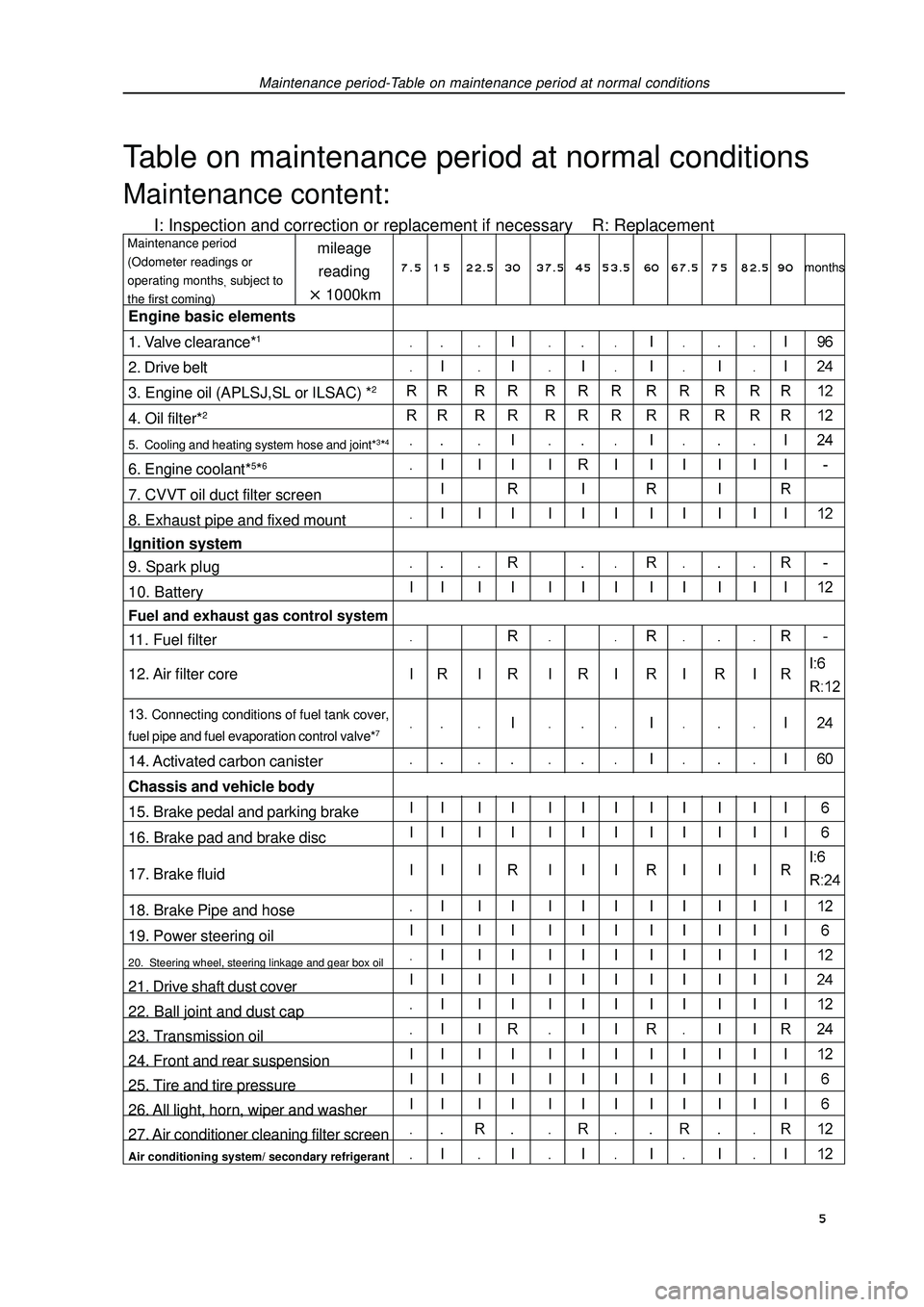
Maintenance period-Table on maintenance period at normal conditionsTable on maintenance period at normal conditionsMaintenance content:I: Inspection and correction or replacement if necessary R: Replacementmileage
reading1000kmMaintenance period
(Odometer readings or
operating monthssubject to
the first coming)Engine basic elements
1. Valve clearance*12. Drive belt
3. Engine oil (APLSJ,SL or ILSAC) *24. Oil filter*25. Cooling and heating system hose and joint*3*46. Engine coolant*5*67. CVVT oil duct filter screen
8. Exhaust pipe and fixed mount
Ignition system
9. Spark plug
10. BatteryFuel and exhaust gas control system11. Fuel filter
12. Air filter core13. Connecting conditions of fuel tank cover,
fuel pipe and fuel evaporation control valve*714. Activated carbon canister
Chassis and vehicle body
15. Brake pedal and parking brake
16. Brake pad and brake disc
17. Brake fluid
18. Brake Pipe and hose
19. Power steering oil20. Steering wheel, steering linkage and gear box oil21. Drive shaft dust cover
22. Ball joint and dust cap
23. Transmission oil
24. Front and rear suspension
25. Tire and tire pressure
26. All light, horn, wiper and washer
27. Air conditioner cleaning filter screenAir conditioning system/ secondary refrigerant7 . 5 1 5 22.5 3037.5 4553.5 60 67.5 7 582.5 90months 5
Page 20 of 419

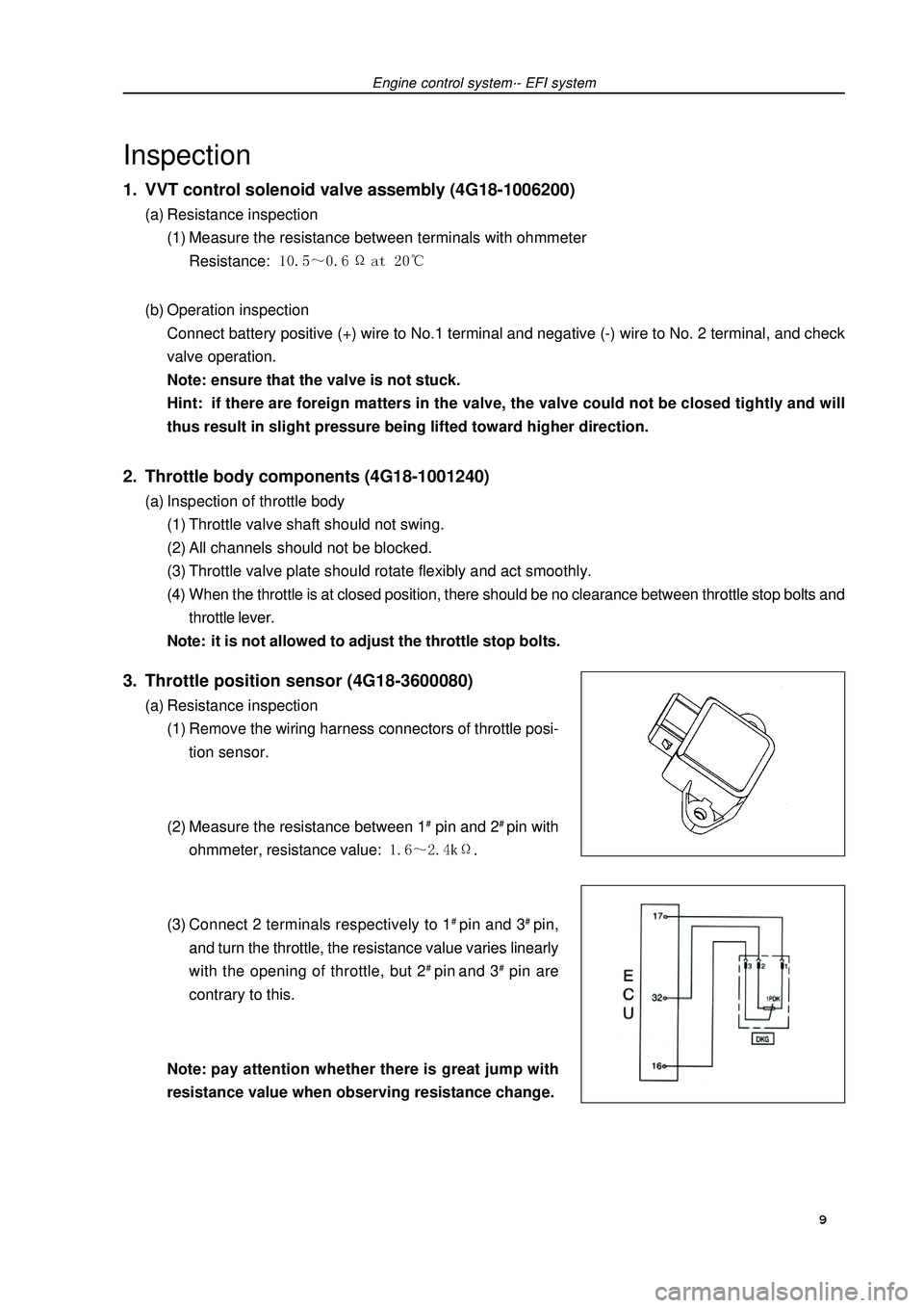
Engine control system·- EFI systemInspection1. VVT control solenoid valve assembly (4G18-1006200)(a) Resistance inspection
(1) Measure the resistance between terminals with ohmmeter
Resistance: (b) Operation inspection
Connect battery positive (+) wire to No.1 terminal and negative (-) wire to No. 2 terminal, and check
valve operation.
Note: ensure that the valve is not stuck.
Hint: if there are foreign matters in the valve, the valve could not be closed tightly and will
thus result in slight pressure being lifted toward higher direction.2. Throttle body components (4G18-1001240)(a) Inspection of throttle body
(1) Throttle valve shaft should not swing.
(2) All channels should not be blocked.
(3) Throttle valve plate should rotate flexibly and act smoothly.
(4) When the throttle is at closed position, there should be no clearance between throttle stop bolts and
throttle lever.
Note: it is not allowed to adjust the throttle stop bolts.3. Throttle position sensor (4G18-3600080)(a) Resistance inspection
(1) Remove the wiring harness connectors of throttle posi-
tion sensor.
(2) Measure the resistance between 1# pin and 2# pin with
ohmmeter, resistance value: .
(3) Connect 2 terminals respectively to 1# pin and 3# pin,
and turn the throttle, the resistance value varies linearly
with the opening of throttle, but 2# pin and 3# pin are
contrary to this.
Note:pay attention whether there is great jump with
resistance value when observing resistance change. 9
Page 21 of 419

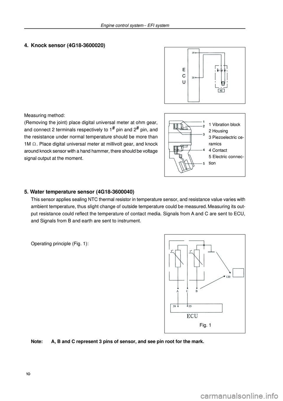
5. Water temperature sensor (4G18-3600040)This sensor applies sealing NTC thermal resistor in temperature sensor, and resistance value varies with
ambient temperature, thus slight change of outside temperature could be measured. Measuring its out-
put resistance could reflect the temperature of contact media. Signals from A and C are sent to ECU,
and Signals from B and earth are sent to instrument.
Operating principle (Fig. 1):
Note: A, B and C represent 3 pins of sensor, and see pin root for the mark. Measuring method:
(Removing the joint) place digital universal meter at ohm gear,
and connect 2 terminals respectively to 1#
pin and 2#
pin, and
the resistance under normal temperature should be more than
1M. Place digital universal meter at millivolt gear, and knock
around knock sensor with a hand hammer, there should be voltage
signal output at the moment.Engine control system·- EFI systemFig. 11 Vibration block
2 Housing
3 Piezoelectric ce-
ramics
4 Contact
5 Electric connec-
tion4. Knock sensor (4G18-3600020) 10
Page 93 of 419

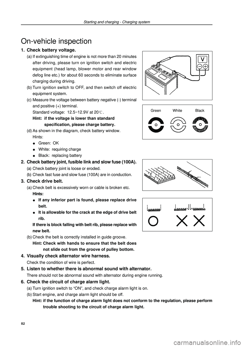
1. Check battery voltage.(a) If extinguishing time of engine is not more than 20 minutes
after driving, please turn on ignition switch and electric
equipment (head lamp, blower motor and rear window
defog line etc.) for about 60 seconds to eliminate surface
charging during driving.
(b) Turn ignition switch to OFF, and then switch off electric
equipment system.
(c) Measure the voltage between battery negative (-) terminal
and positive (+) terminal.
Standard voltage: 12.5~12.9V at 20.
Hint: if the voltage is lower than standard
specification, please charge battery.
(d) As shown in the diagram, check battery window.
Hints:Green: OKWhite: requiring chargeBlack: replacing battery2. Check battery joint, fusible link and slow fuse (100A).(a) Check battery joint is loose or eroded.
(b) Check fast fuse and slow fuse (100A) are in conduction.3. Check drive belt.(a) Check belt is excessively worn or cable is broken etc.
Hints:If any inferior part is found, please replace drive
belt.It is allowable for the crack at the edge of drive belt
rib.
If there is block falling with belt rib, please replace with
new belt.
(b) Check the belt is correctly installed in guide groove.
Hint:Check with hands to ensure that the belt does
not slide out from the groove of pulley bottom.4. Visually check alternator wire harness.Check the condition of wire is perfect.Starting and charging - Charging systemOn-vehicle inspectionGreen White Black5. Listen to whether there is abnormal sound with alternator.There should not be abnormal sound with alternator during engine running.6. Check the circuit of charge alarm light.(a) Turn ignition switch to “ON”, and check charge alarm light is on.
(b) Start engine, and charge alarm light should be off.
Hint: if the function of charge alarm light does not conform to the regulation, please perform
trouble shooting to the circuit of charge alarm light.82
Page 147 of 419

Brake--Remove malfunction2. Check the free travel of pedal.(a) Extinguish the engine, and step brake pedal repeatedly until
there is no vacuum in vacuum booster.
(b) Press down pedal with hand until feeling the resistance,
then measure the distance of this section, liking that shown
in figure.
Free travel of pedal: 1-6mm.
If it is wrong, check the clearance of brake light switch.
Clearance of brake light switch: 0.5-2.4mm
If the clearance accords with the regulation, remove the
malfunction in brake system.3. Check the distance from pedal to floor.Release parking brake drag lever
When engine is running, step down brake pedal, then mea-
sure the distance from pedal to floor, liking that shown in figure,
Force 490 N on pedal, its distance from floor should be:
over 60mm.
If it is wrong, remove the malfunction in brake system.Brake pedal assemblyAdjustment1. Check and adjust the height of brake pedal.(a) Check the height of brake pedal.
Pedal distance from floor: 136.0-146.0mm
(b) Adjust the height of brake pedal.
(1) Disassemble lower trim board of panel.
(2) Disassemble switch joint of brake light.
(3) Loosen locking nut of brake switch, and disassemble
the switch of brake light.
(4) Loosen U-shaped clasp fixing nut of pedal lever.
(5) Turn pedal lever to adjust the height of pedal.
(6) Lock the fixing nut of lever.
Torque: 26
± ±± ±
±2 N⋅ ⋅⋅ ⋅
⋅m
(7) Assemble the switch of brake switch.
(8) Connect the switch joint of brake light.
(9) Press down the brake pedal for 5-15mm, and turn the switch of brake light to illuminate brake light,
then lock the nut.
(10) After assembling, press down the brake pedal for 5-15mm again, and confirm brake light has
illuminated.Pedal distance
from floorFree travel of
pedal Height of pedal Push rodBrake light switch136