Page 13 of 419

Brief introduction on Geely model “FC” Basic parametersTable 2 Types and parameters of main assemblyModel
TypeElectric injection system modelBore
StrokeDelivery capacityCompression ratioMax. power
Max. torque
Idling speedIgnition sequenceMin. fuel consumptionTypeMain gear box ratioTypes and parameters
JL4G184-cylinderin-line, four-stroke, water-cooling, double over-head
camshaft, 16-valve, CVVT multipoint injection gasoline engineUnited Automotive Electronic Systems Co., Ltd. M7.9.7 electric injection system5 gears synchronizer of constant mesh gearDry single, diaphragm spring, constant pressure
Rack-and-pinion steering gear with hydraulic powerDouble pipeline, vacuum boosterwith ABS +EBD anti-lock systemDisc brake
Disc brake
Strut-type front independent suspensionLongitudinal swinging arm and anti-twist beam compound rear suspensionBreakawayBalI cage and tripot type constant velocity universal jointLoaded all-metal body
Honeycomb cordierite carrier, noble metal catalyst
Swirl or swash plate compressorItem nameNumber
Engine1st gear
2nd gear
3rd gear
4th gear
5th gearReverse gearClutch type
Steering gear
Tire
Body structureSpecification
Air pressureRadial
tireTail gasAir
condi-
tioning
systemUnit
��
��
�
��/�/���
�.
�/�/���
�/���
�/��.
�
���
�
2
Transmission
Each gear ratio
Braking
system
Sus-
pension
Drive
axleType
Front brake
Rear brakeFront suspension type
Rear suspension typeRim
Type
Drive shaftCatalytic converterCompressor typeNominal refrigerating capacityRefrigerant
Page 24 of 419

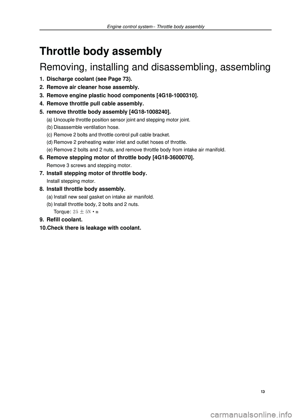
Engine control system·- Throttle body assemblyThrottle body assemblyRemoving, installing and disassembling, assembling1. Discharge coolant (see Page 73).
2. Remove air cleaner hose assembly.
3. Remove engine plastic hood components [4G18-1000310].
4. Remove throttle pull cable assembly.
5. remove throttle body assembly [4G18-1008240].(a) Uncouple throttle position sensor joint and stepping motor joint.
(b) Disassemble ventilation hose.
(c) Remove 2 bolts and throttle control pull cable bracket.
(d) Remove 2 preheating water inlet and outlet hoses of throttle.
(e) Remove 2 bolts and 2 nuts, and remove throttle body from intake air manifold.6. Remove stepping motor of throttle body [4G18-3600070].Remove 3 screws and stepping motor.7. Install stepping motor of throttle body.Install stepping motor.8. Install throttle body assembly.(a) Install new seal gasket on intake air manifold.
(b) Install throttle body, 2 bolts and 2 nuts.
Torque: 9. Refill coolant.
10.Check there is leakage with coolant.
13
Page 30 of 419
Fuel-Injection nozzle assembly9. Install fuel rail component [4G18-1112110].(a) Check injection nozzle o-ring and replace if there is damage.
(b) Install isolator on cylinder head.
(c) Install fuel rail component together with injection nozzle.
Torque:(d) Install fuel pipe fixing clip.
Torque: m10. Check the function of electric fuel pump and check there is fuel leakage.
19
Page 31 of 419

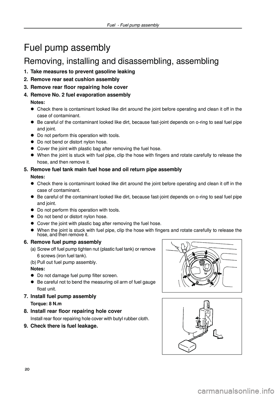
Fuel - Fuel pump assemblyFuel pump assemblyRemoving, installing and disassembling, assembling1. Take measures to prevent gasoline leaking
2. Remove rear seat cushion assembly
3. Remove rear floor repairing hole cover
4. Remove No. 2 fuel evaporation assemblyNotes:
�zCheck there is contaminant looked like dirt around the joint before operating and clean it off in the
case of contaminant.
�zBe careful of the contaminant looked like dirt, because fast-joint depends on o-ring to seal fuel pipe
and joint.
�zDo not perform this operation with tools.
�zDo not bend or distort nylon hose.
�zCover the joint with plastic bag after removing the fuel hose.
�zWhen the joint is stuck with fuel pipe, clip the hose with fingers and rotate carefully to release the
hose, and then remove it.5. Remove fuel tank main fuel hose and oil return pipe assemblyNotes:
�zCheck there is contaminant looked like dirt around the joint before operating and clean it off in the
case of contaminant.
�zBe careful of the contaminant looked like dirt, because fast-joint depends on o-ring to seal fuel pipe
and joint.
�zDo not perform this operation with tools.
�zDo not bend or distort nylon hose.
�zCover the joint with plastic bag after removing the fuel hose.
�zWhen the joint is stuck with fuel pipe, clip the hose with fingers and rotate carefully to release the
hose, and then remove it.6. Remove fuel pump assembly(a) Screw off fuel pump tighten nut (plastic fuel tank) or remove
6 screws (iron fuel tank).
(b) Pull out fuel pump assembly.
Notes:
�zDo not damage fuel pump filter screen.
�zBe careful not to bend the measuring oil arm of fuel gauge
float unit.7. Install fuel pump assemblyTorque: 8 N.m8. Install rear floor repairing hole coverInstall rear floor repairing hole cover with butyl rubber cloth.9. Check there is fuel leakage. 20
Page 33 of 419

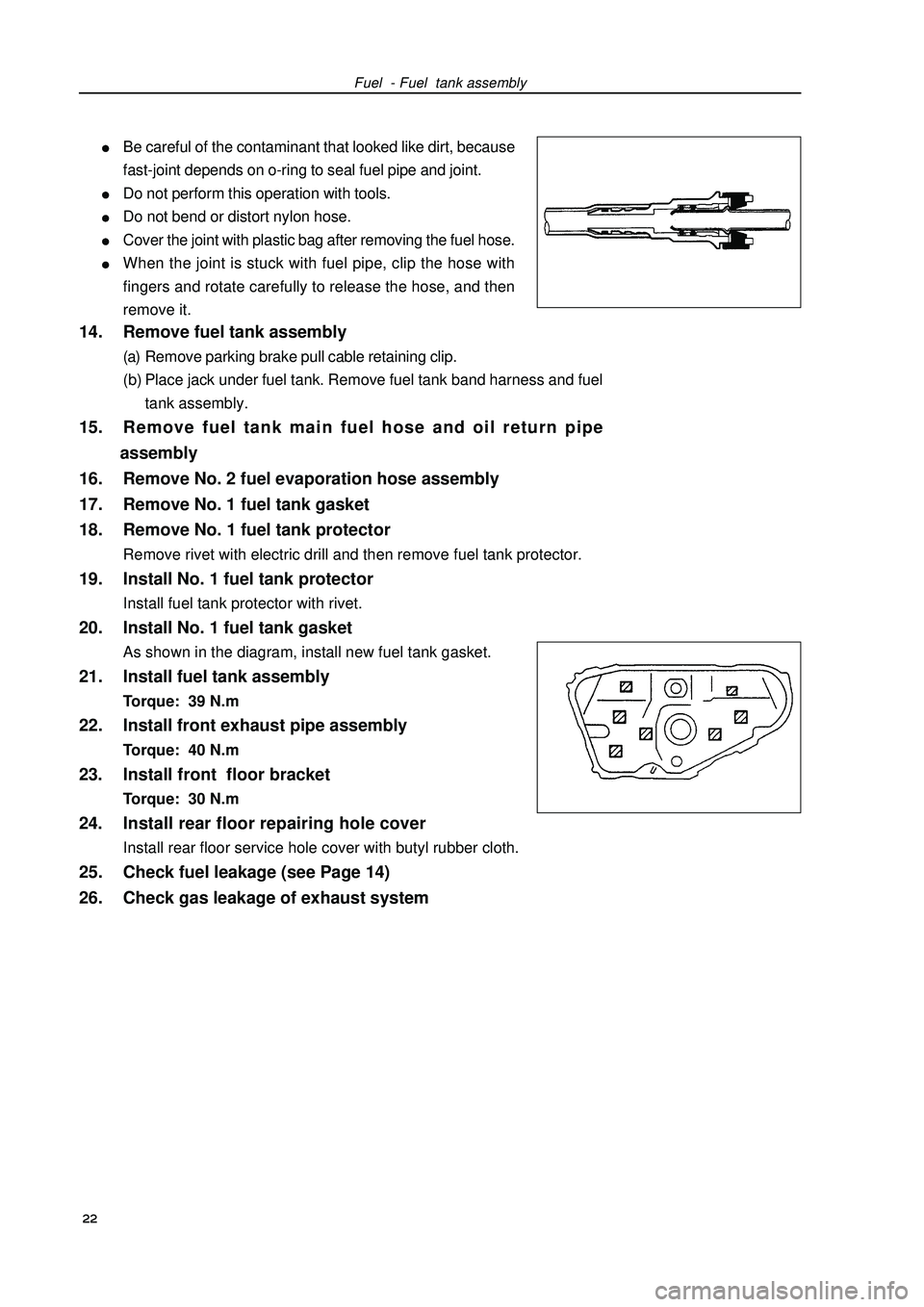
Fuel - Fuel tank assemblyBe careful of the contaminant that looked like dirt, because
fast-joint depends on o-ring to seal fuel pipe and joint.Do not perform this operation with tools.Do not bend or distort nylon hose.Cover the joint with plastic bag after removing the fuel hose.When the joint is stuck with fuel pipe, clip the hose with
fingers and rotate carefully to release the hose, and then
remove it.14. Remove fuel tank assembly(a) Remove parking brake pull cable retaining clip.
(b) Place jack under fuel tank. Remove fuel tank band harness and fuel
tank assembly.15. Remove fuel tank main fuel hose and oil return pipe
assembly
16. Remove No. 2 fuel evaporation hose assembly
17. Remove No. 1 fuel tank gasket
18. Remove No. 1 fuel tank protectorRemove rivet with electric drill and then remove fuel tank protector.19. Install No. 1 fuel tank protectorInstall fuel tank protector with rivet.20. Install No. 1 fuel tank gasketAs shown in the diagram, install new fuel tank gasket.21. Install fuel tank assemblyTorque: 39 N.m22. Install front exhaust pipe assemblyTorque: 40 N.m23. Install front floor bracketTorque: 30 N.m24. Install rear floor repairing hole coverInstall rear floor service hole cover with butyl rubber cloth.25. Check fuel leakage (see Page 14)
26. Check gas leakage of exhaust system
22
Page 44 of 419
Engine mechanism - Valve clearance(n) Check intake side camshaft bearing cover forward re-
mark and figure, and tighten the bolts as sequences
shown in the diagram.
Torque: (o) Align alignment mark on the chain with timing mark on
camshaft timing sprocket, and place exhaust camshaft
in cylinder head.
(p) Temporarily lock fixed bolts.
(q) Check exhaust side camshaft bearing cover forward
remark and figure, and tighten the bolts as sequences
shown in the diagram.
Torque: (r) Install camshaft front bearing cover.
Torque: (s) Fix camshaft with adjustable wrench and then tighten
the fixed bolts of camshaft timing sprocket.
Torque: Note: be careful not to damage valve lifter.33Timing remark chain linkTiming markTighteningFixing
Page 46 of 419

Engine mechanism - Valve clearance(4) Turn crankshaft clockwise, and check the sliding
parts are blocked by plunger.
Hint: if the plunger does not eject, press the chain ten-
sion rail toward chain tensioner with screwdriver
or fingers to separate the hook from lock pin and
make the plunger eject.11.Install cylinder head cover components.(a) Install cylinder head cover gasket on cylinder head cover.
(b) Eliminate all old sealant (FIPG) materials.
(c) Coat sealant on 2 positions shown in the diagram.
Notes:Wipe off all the oil stains on junction plane.After coating sealant, finish installation of cylinder head
cover within 3 minutes.After installing, do not refill engine oil within 2 minutes.
(d) Install cylinder head cover components with 9 bolts, 2 seal washers and 2 nuts.
Evenly tighten bolts and nuts at several times.
Torque:
Short bolt: Nut, long bolt etc.: m12. Install drive belt tensioner device.Torque: nut: Bolt: 13. Install fixing bracket absorber on the left of engine.Torque: 14. Check there is oil leakage.Sealant 35 Plunger
TurningPushing
Page 50 of 419

34. Remove power steering pump assembly.
35. Remove sub frame together with side member.(a) Remove front engine mounting assembly and rear en-
gine mounting assembly from engine assembly.
(b) Remove sub frame assembly.36. Remove starter mounting components
[4G18-3708100].
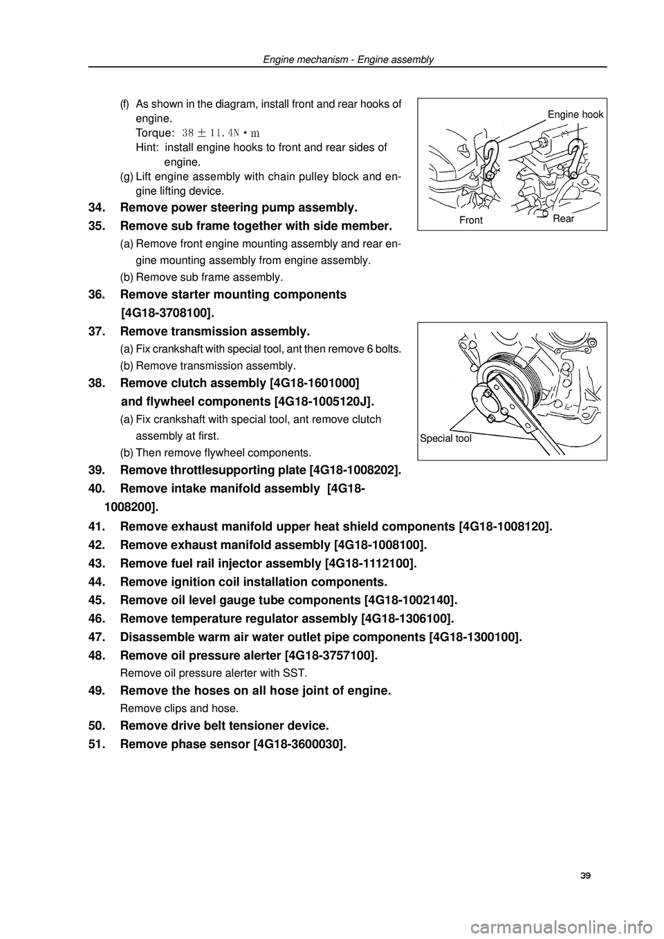
37. Remove transmission assembly.(a) Fix crankshaft with special tool, ant then remove 6 bolts.
(b) Remove transmission assembly.38. Remove clutch assembly [4G18-1601000]
and flywheel components [4G18-1005120J].(a) Fix crankshaft with special tool, ant remove clutch
assembly at first.
(b) Then remove flywheel components.39. Remove throttlesupporting plate [4G18-1008202].
40. Remove intake manifold assembly [4G18-
1008200].(f) As shown in the diagram, install front and rear hooks of
engine.
Torque: Hint: install engine hooks to front and rear sides of
engine.
(g) Lift engine assembly with chain pulley block and en-
gine lifting device.Engine mechanism - Engine assemblySpecial tool39 41. Remove exhaust manifold upper heat shield components [4G18-1008120].
42. Remove exhaust manifold assembly [4G18-1008100].
43. Remove fuel rail injector assembly [4G18-1112100].
44. Remove ignition coil installation components.
45. Remove oil level gauge tube components [4G18-1002140].
46. Remove temperature regulator assembly [4G18-1306100].
47. Disassemble warm air water outlet pipe components [4G18-1300100].
48. Remove oil pressure alerter [4G18-3757100].Remove oil pressure alerter with SST.49. Remove the hoses on all hose joint of engine.Remove clips and hose.50. Remove drive belt tensioner device.
51. Remove phase sensor [4G18-3600030].Engine hook
FrontRear