Page 89 of 419

Ignition - Ignition system3. Inspection of ignition coil (including igniter) and spark test(a) Check DTC.
Note: if there is display with DTC, perform trouble shooting according to DTC procedure.
(b) Check there is spark.
(1) Remove ignition coil (including igniter).
(2) Remove spark plug with 16mm spark plug sleeve.
(3) Install spark plug to each ignition coil (including igniter), and connect ignition coil joint.
(4) Uncouple joints of 4 injection nozzles.
(5) Earth spark plug.
(6) Check spark with engine running.
Notes:Be sure to earth spark plug during checking. When there is falling or collision with ignition coil,please replace with a new oneRunning engine time for each time should not be more than 2 seconds.
If there is no spark, please perform test as the following steps.
(c) Install spark plug with 16mm spark plug sleeve.
Torque: (d) Install ignition coil and igniter.
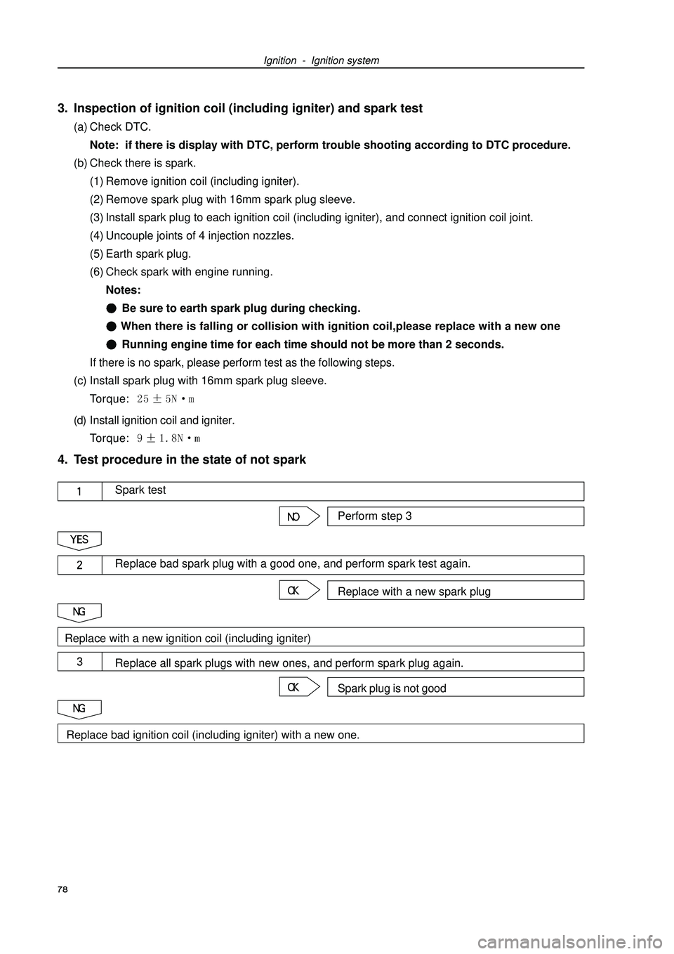
Torque: 4. Test procedure in the state of not spark
78Perform step 3Spark testReplace with a new spark plugReplace bad spark plug with a good one, and perform spark test again.Spark plug is not goodReplace all spark plugs with new ones, and perform spark plug again.Replace with a new ignition coil (including igniter)Replace bad ignition coil (including igniter) with a new one.
Page 91 of 419
Starting and charging - Starting system(f) Connect magnetic field coil wire to terminal C.
(h) Torque: (i) Clamp starter with jaw vice.
(j) As shown in the diagram, connect battery with ampere
meter.
(k) Read current value displayed on ampere meter.
(l) Current value specification: 90 A or lower at 11.5 V.2. Starter relay80Terminal 50Terminal 30Ampere
meter Specified
conditions
Normal stateConductionConductionTerminal connected
by three-use meter Conditions
Supply battery voltage
to No. 1 and No. 2
terminals
Page 95 of 419
Starting and charging - Alternator componentsAlternator componentsReplacement1. Remove engine right bottom shield.
2. Remove drive belt.Slowly turn drive belt tensioner clockwise to loosen the belt,
then remove drive belt and put back the tensioner slowly to
completely loosen it.3. Remove alternator components.(a) Remove rubber cover and nuts.
(b) Uncouple alternator joint.
(c) Remove 2 bolts and alternator.4. Install alternator components.Torque:12mm head bolt : m
14mm head bolt : 84
Page 96 of 419
Starting and charging - Starter componentsStarter componentsReplacement1. Remove engine lower left shield.
2. Remove starter components.(b) Uncouple starter joint.
(b) Remove nuts, and uncouple starter wire.
(c) Remove 2 bolts and starter.3. Install Starter components.Torque:bolt: Wire harness: 85
Page 99 of 419

Inside wheel38o452oOutside wheel: reference32o50Front suspension - Front wheel alignment(Coarse road)
Inside wheel39o052oOutside wheel: reference33o10Camber-031’45’Left-right error45’Caster242’45’Left-right error45’Steering shaft inclination18’45’Left-right error45’Camber-
018’45’Left-right error45’Caster230’45’Left-right error45’Steering shaft inclination1052’45’Left-right error45’A: inside
B: outsideFrontGauge If caster and steering axis inclination are not within specification, please adjust the caster and
then check parts of lower control arm is damaged or worn.(b) Loosen lock nuts at the end of transversal lever .
(c) Evenly rotate end levers of left and right rack to
adjust toe-in.
Hint: try adjusting toe-in to medium value.
(d) Ensure that the end lever length of left rack equals that
of right rack.
(e) Tighten lock nuts at the end of transversal lever.
Torque: 745 N.m
(f) Install dust cover fixing clip.
Hint: ensure that the dust cover does not distort.5. Inspection of turning angle(a) Completely rotate steering wheel to the bottom and then
measure turning angle.
Turning angle:
(General road)
(Coarse road)Wheel
alignment
tester88If left and right inside wheels are not within specification, please check the end lever length of left rack
and right rack.6. Inspection of camber, caster and steering shaft inclination(a) Install camber-caster-kingpin gauge or erect wheel alignment tester.
(b) Check camber, caster and steering-axis inclination.
Camber, caster and steering shaft inclination:
(General road)
Page 100 of 419
Front suspension - Front wheel alignment7. Adjustment of camberNote: after adjusting the camber, please check toe-in.
(a) Remove front wheels.
(b) Remove 2 nuts under absorber.
If it is necessary to repeat using bolts or nuts, please coat
oil to thread of nuts.
(c) Clean nut absorber and attachment face of steering knucle.
(d) Temporarily install 2 nuts.
(e) Push or pull lower end of absorber in the direction that cam-
ber requires adjustment to adjust the camber.
(f) Tighten nut.
Torque: 15310 N.m
(g) Install front wheels.
Torque: 10310 N.m
(h) Check camber.89
Page 103 of 419
Front suspension - Front shock absorber and helical spring(e) As shown in the diagram, install upper insulator.
(f) Install spring seat to absorber with mark toward outside of
vehicle.
(g) Install new dustproof seal ring and upper absorber bearing.
(h) Fix upper shock absorber bearing with special tool, and
install new nuts.
Torque: 475 N.m
(i) Remove special tool.
(j) Install dust cover.
(k) Coat upper absorber bearing with grease.
Note: do not coat grease on rubber surface of upper
shock absorber bearing.8. Install front shock absorber and helical spring.(a) Install 3 nuts above shock absorber.
Torque: 393 N.m
(b) Install 2 fixed bolts of shock absorber.Outside
Grease92Outside
Page 104 of 419
Front suspension - Front shock absorber and helical springHandling1. Handle front left absorber assembly.(a) Completely pull out absorber piston rod.
(b) As shown in the diagram, drill a small hole on cylinder body
between two lines with electric drill to make inside gas flow
out
Notes:Iron chip may fly out during drilling, please be care-
ful in operating.The gas is colorless, odorless and nontoxic.93(c) Install 2 nuts to lower end of absorber.
Torque: 15310 N.m
Hint: coat oil on thread of nuts.
(d) Install brake hose and ABS speed sensor wire harness
bracket with bolts.
Torque: 19N.m9. Install front left stabilizer link assembly [64000097].Install stabilizer link with nuts.
Torque: 745 N.m
Hint: if ball joint rotates with nuts, please fix bolts with
hexagonal wrench (6mm).10. Install front wheels.Torque: 10310 N.m11. Check and adjust front wheel alignment
(see Page 87).