2008 GEELY FC timing belt
[x] Cancel search: timing beltPage 6 of 419

Brief introduction on Geely model “FC”
Basic parameters...................................................
1
Maintenance period
Regular maintenance items...................................
4
Table on maintenance period at normal conditions5
Table on maintenance period at severe conditions..
7
Engine control system
EFI system.............................................................
8
On-vehicle inspection........................................
8
Inspection..........................................................
9
Throttle body assembly........................................
13Removing, installing and disassembling, assembling...13
Fuel
Fuel system..........................................................
14
Precautions......................................................
14
On-vehicle inspection......................................
16
Inspection........................................................
17
Injection nozzle assembly....................................
18
Replacement...................................................
18
Fuel pump assembly...........................................
20Removing, installing and disassembling, assembling....20
Fuel tank assembly.............................................
21Removing, installing and disassembling, assembling.....21
Exhaust gas control
Exhaust gas control system...............................
23
On-vehicle inspection......................................
23
Inspection........................................................
25
Engine mechanism
Engine assembly..................................................
26Inspection........................................................
26
Drive belt..............................................................
29
Replacement...................................................
29
Valve clearance....................................................
30
Adjustment......................................................
30
Engine assembly.................................................
36
Replacement...................................................
36
Timing chain assembly.......................................
45
Replacement...................................................
45
Camshaft.............................................................
52
Replacement...................................................
52
Crankshaft front oil seal assembly.....................
60
Replacement...................................................
60
Crankshaft rear oil seal assembly......................
62
Replacement...................................................
62
Cylinder cover gasket components.....................
63
Replacement...................................................
63
Exhaust
Exhaust pipe assembly........................................
65Removing, installing and disassembling, assembling.....65
Cooling
Cooling system....................................................
66
On-vehicle inspection......................................
66
Inspection........................................................
66
Cooling fan system..............................................
68
On-vehicle inspection......................................
68
Inspection........................................................
68
Water pump assembly........................................
69
Replacement...................................................
69
Temperature regulator components...................
71
Replacement...................................................
71
Radiator with electronic fan assembly................
72Contents
Page 37 of 419
![GEELY FC 2008 Workshop Manual Engine mechanismEngine assemblyInspection1. Check coolant.
2. Check engine oil.
3. Check battery.
4. Check air filter assembly.
5. Check spark plug [4G18-3705113].
6. Check drive belt [4G18-1307107].H GEELY FC 2008 Workshop Manual Engine mechanismEngine assemblyInspection1. Check coolant.
2. Check engine oil.
3. Check battery.
4. Check air filter assembly.
5. Check spark plug [4G18-3705113].
6. Check drive belt [4G18-1307107].H](/manual-img/58/57161/w960_57161-36.png)
Engine mechanismEngine assemblyInspection1. Check coolant.
2. Check engine oil.
3. Check battery.
4. Check air filter assembly.
5. Check spark plug [4G18-3705113].
6. Check drive belt [4G18-1307107].Hint: do not check belt tension, because automatic tensioner is applied.7. Check ignition timing.(a) Warm up engine.
(b) Connect timing lamp to engine.
(c) Check ignition timing at idle speed.
Ignition timing: before top dead center Note: when checking ignition timing, place
transmission at neutral position.
Hint: After run the engine for 5 seconds with rotating
speed of 1000-1300rpm, check the engine could
recover to idle running.8. Check engine idle speed.(a) Warm up engine and run it at idle speed.
(b) Read engine rotating number in data flow with diagnostic instrument.
(c) Check idle speed.
Idle speed: about 750-850rpm
Notes:When checking idle speed, place cooling fan at OFF position.Turn off all auxiliary devices and air conditioner.Engine mechanism - Engine assemblyK-line 26
Page 41 of 419
![GEELY FC 2008 Workshop Manual Engine mechanism - Valve clearanceValve clearanceAdjustment1. Remove engine plastic hood components.
2. Remove ignition coil components [4G18-3705110].
3. Remove cylinder head cover components [4G18-
GEELY FC 2008 Workshop Manual Engine mechanism - Valve clearanceValve clearanceAdjustment1. Remove engine plastic hood components.
2. Remove ignition coil components [4G18-3705110].
3. Remove cylinder head cover components [4G18-](/manual-img/58/57161/w960_57161-40.png)
Engine mechanism - Valve clearanceValve clearanceAdjustment1. Remove engine plastic hood components.
2. Remove ignition coil components [4G18-3705110].
3. Remove cylinder head cover components [4G18-
1003130].
4. Remove engine right bottom shield.
5. Turn crankshaft to cylinder 1 compression top dead
center position.(a) Turn crankshaft pulley to align its groove with “o” mark on
timing chain hood.
(b) Check dot marks on camshaft timing sprocket and VVT
timing sprocket, and they should be in a line on timing chain
hood surface as shown in the diagram.
Hint: if not, turn crankshaft for one circle again
and align the above marks.6. Check valve clearance.(a) Only check the valves shown in the diagram.
(1) Measure the clearance between valve tappet and cam-
shaft with plug gauge.
(2) Record valve clearance measuring value exceeding
specification, and this value will be used to determine
valve tappet thickness that needs change.
Valve clearance (cold vehicle)Intake airExhaust(b) Turn crankshaft for one circle ), and cylinder 4 is
turned to compression top dead center position.
(c) Only check the valves shown in the diagram. Measure valve
clearance (see step (a)).7. Remove drive beltSlowly turn drive belt tensioner clockwise to loosen it.
Then remove drive belt and put back drive belt tensioner slowly
and gently. 30 Mark
Mark
Mark
Timing chain
hood surface
Groove
Page 42 of 419

Engine mechanism - Valve clearance8. Remove right engine mounting assembly(a) Remove PS oil pump reservoir and put it aside.
(b) Place wooden block between jack and engine, properly
place the jack, and then remove right engine mounting
assembly.9. Remove drive belt tensioner device [4G18-
1300200].Hint: operate the jack up and down to remove bolts.10. Adjust valve clearance.Note: do not turn crankshaft before installing chain
tensioner.
(a) Turn crankshaft to cylinder 1 top dead center position.
(b) Align the marks on timing chain and camshaft timing
sprocket.
(c) Remove 2 bolts and chain tensioner.
(d) Fix camshaft with adjustable wrench and then loosen
the fixed bolts of exhaust camshaft timing sprocket.
Note: be careful not to damage valve lifter.
(e) As sequences shown in the diagram, loosen camshaft
bearing cover bolts on exhaust camshaft at several
times and remove the bearing cover at the same time.
(f) As shown in the diagram, remove exhaust camshaft
timing sprocket.Painting
mark
LooseningFixing 31
Page 55 of 419

Engine mechanism - Engine assembly85. Install alternator mounting components.Torque: 12mm bolt head A: 14mm bolt head B: 86. Install drive belt.
87. Install engine wire harness and all hoses
not connected.(a) Check and connect all joints of engine wire harness.
(b) Check and connect all hoses.88. Install transmission control pull cable assembly
and valve control pull cable.
89. Install air filter assembly and its hose.
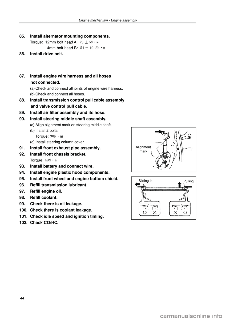
90. Install steering middle shaft assembly.(a) Align alignment mark on steering middle shaft.
(b) Install 2 bolts.
Torque: m
(c) Install steering column cover.91. Install front exhaust pipe assembly.
92. Install front chassis bracket.Torque: 93. Install battery and connect wire.
94. Install engine plastic hood components.
95. Install front wheel and engine bottom shield.
96. Refill transmission lubricant.
97. Refill engine oil.
98. Refill coolant.
99. Check there is oil leakage.
100. Check there is coolant leakage.
101. Check idle speed and ignition timing.
102. Check CO/HC.Alignment
mark
Sliding in
Pulling 44
Page 56 of 419

Engine mechanism - Timing chain assemblyTiming chain assemblyReplacement1. Remove engine left bottom shield.
2. Remove engine right bottom shield.
3. Discharge coolant.
4. Remove engine plastic hood components.
5. Remove drive belt.
6. Remove power steering pump assembly.
7. Remove alternator assembly.
8. Uncouple engine wire harness.(a) Remove ignition coil joint, PS fuel pressure switch joint,
fuel line control joint and speed sensor joint.
(b) Remove bolts and nuts of fixed earth wire and put aside
engine wire harness.9. Remove ignition coil assembly.
10. Remove cylinder head cover components.(a) Remove fuel pipe retaining clip and 2 PCV hoses from
cylinder head cover.
(b) Remove 9 bolts, 2 seal washers, cylinder head cover
components and gasket.11. Remove right engine mounting assembly.(a) Remove PS oil pump reservoir and put it aside.
(b) Place wooden block between jack and engine, prop-
erly place the jack, and then remove right engine mount-
ing assembly.12. Turn crankshaft to cylinder 1 compression top
dead center position.
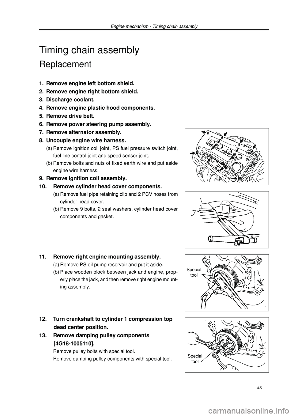
13. Remove damping pulley components
[4G18-1005110].Remove pulley bolts with special tool.
Remove damping pulley components with special tool.Special
tool
Special
tool45
Page 57 of 419
![GEELY FC 2008 Workshop Manual Engine mechanism - Timing chain assembly14. Remove drive belt tensioner device.Hint: operate the jack up and down to remove bolts.15. Remove water pump components [4G18-1307110].(a) Remove 6 bolts an GEELY FC 2008 Workshop Manual Engine mechanism - Timing chain assembly14. Remove drive belt tensioner device.Hint: operate the jack up and down to remove bolts.15. Remove water pump components [4G18-1307110].(a) Remove 6 bolts an](/manual-img/58/57161/w960_57161-56.png)
Engine mechanism - Timing chain assembly14. Remove drive belt tensioner device.Hint: operate the jack up and down to remove bolts.15. Remove water pump components [4G18-1307110].(a) Remove 6 bolts and water pump components.16. Remove engine stabilizer bracket on engine cross
member.
17. Remove compressor.
18. Remove speed sensor.
19. Remove chain tensioner components
[4G18-1006160].Note: do not turn crankshaft before installing chain
tensioner components.20. Remove timing chain hood components
[4G18-1006140].(a) Remove 11 bolts and nuts.
(b) Remove studs with star wrench.
(c) Pry open timing chain hood from timing chain hood pro-
trusion part between cylinder head and body with screw-
driver and remove it.
Note: be careful not to damage timing chain
hood, the contact surface of cylinder head and
body.21. Remove crankshaft front oil seal assembly
[4G18-1006150].Remove oil seal with screwdriver.22. Remove speed sensor signal panel
[4G18-3600011A].
23. Remove chain tension rail components
[4G18-1006120].
24. Remove chain guide rail components
[4G18-1006130].
25. Remove timing chain [4G18-1006110].Remove it with 2 screwdrivers.
Notes:Place a piece of cloth to protect engine.In the state of timing chain separating from timing
sprocket and turning camshaft, turn crankshaft 1/4
circle to avoid valve contacting with piston.26. Install timing chain.(a) Turn crankshaft to cylinder 1 compression top dead
center position.
(1) Turn camshaft from hexagon head part of
camshaft, and align dot marks on camshaft timing
sprocket.46
Page 61 of 419
![GEELY FC 2008 Workshop Manual Engine mechanism - Timing chain assembly34. Install speed sensor.Torque: 35. Install engine fixing bracketTorque: 36. Install water pump mounting components
[4G18-1307100].(a) Install new o-ring GEELY FC 2008 Workshop Manual Engine mechanism - Timing chain assembly34. Install speed sensor.Torque: 35. Install engine fixing bracketTorque: 36. Install water pump mounting components
[4G18-1307100].(a) Install new o-ring](/manual-img/58/57161/w960_57161-60.png)
Engine mechanism - Timing chain assembly34. Install speed sensor.Torque: 35. Install engine fixing bracketTorque: 36. Install water pump mounting components
[4G18-1307100].(a) Install new o-ring on water pump.
(b) Install water pump with 6 bolts.
Torque: bolt A: m37. Install drive belt tensioner device.Torque: nut: Bolt: m38. Install right engine mounting assembly.Torque: 39. Install cylinder head cover components.(a) Install gasket to cylinder head cover.
(b) Eliminate all old seal materials.
(c) Coat sealant on 2 positions shown in the diagram.
Sealant: silicon rubber flange sealant 1596
(Kesaixin 1596).
Notes:Eliminate all grease on contact surface.After coating sealant, finish installation of cylinder
head cover within 3 minutes.After installing, do not refill engine oil within 2
minutes.
(d) Install cylinder head cover and cable bracket with 9 bolts,
2 seal washers and 2 nuts.
Torque: nut: Bolt: m40. Install ignition coil mounting components.Torque: 50