Page 61 of 419
Engine mechanism - Timing chain assembly34. Install speed sensor.Torque: 35. Install engine fixing bracketTorque: 36. Install water pump mounting components
[4G18-1307100].(a) Install new o-ring on water pump.
(b) Install water pump with 6 bolts.
Torque: bolt A: m37. Install drive belt tensioner device.Torque: nut: Bolt: m38. Install right engine mounting assembly.Torque: 39. Install cylinder head cover components.(a) Install gasket to cylinder head cover.
(b) Eliminate all old seal materials.
(c) Coat sealant on 2 positions shown in the diagram.
Sealant: silicon rubber flange sealant 1596
(Kesaixin 1596).
Notes:Eliminate all grease on contact surface.After coating sealant, finish installation of cylinder
head cover within 3 minutes.After installing, do not refill engine oil within 2
minutes.
(d) Install cylinder head cover and cable bracket with 9 bolts,
2 seal washers and 2 nuts.
Torque: nut: Bolt: m40. Install ignition coil mounting components.Torque: 50
Page 76 of 419

Exhaust - Exhaust pipe assemblyExhaustExhaust pipe assemblyRemoving, installing and disassembling, assembling1. Remove oxygen sensor.(a) Uncouple oxygen sensor joint.
(b) Remove oxygen sensor.2. Remove exhaust pipe guard [64000051].
3. Remove front exhaust pipe together with three-way catalytic converter assembly
[64000042].
4. Remove middle exhaust pipe together with middle silencing device assembly [64000043].
5. Remove rear exhaust pipe together with rear silencing device assembly [64000044].
6. Install front exhaust pipe together with three-way catalytic converter assembly [64000042].(a) Measure free length of compression spring with vernier caliper.
Free length: 43mm
Hint: if the free length does dot reach the standard value, it is necessary to replace compres-
sion spring.
(b) Gently knock silencing device inlet seal ring to exhaust manifold with hammer and wooden block until
the surfaces are parallel and level with each other.
Notes:Gently knock gasket toward positive direction.Do not repeat using the gasket that has been removed.Do not push the gasket in by means of tightening
bolt connection.
(c) Install exhaust pipe.
Torque: 43 N.m7. Install oxygen sensor.Torque: 44 N.m9. Install rear exhaust pipe together with rear guard
assembly [64000044].(a) Measure free length of compression spring with vernier
caliper.
Free length: 40mm
Hint: if the free length does dot reach the standard value, it is necessary to replace com-
pression spring.
(b) Install tail pipe to front pipe using a new gasket.
Torque: 43 N.m10. Install front exhaust pipe guard [64000051].
11. Check there is gas leakage with exhaust system.wooden
blockGaskett8. Install middle exhaust pipe together with middle si-
lencing device assembly [64000043].Couple front intake pipe of middle exhaust pipe together with
middle silencing device assembly with outlet pipe of front ex-
haust pipe together with three-way catalytic converter using a
new gasket.Torque: 43 N.mTail pipe sideGasket65
Page 79 of 419

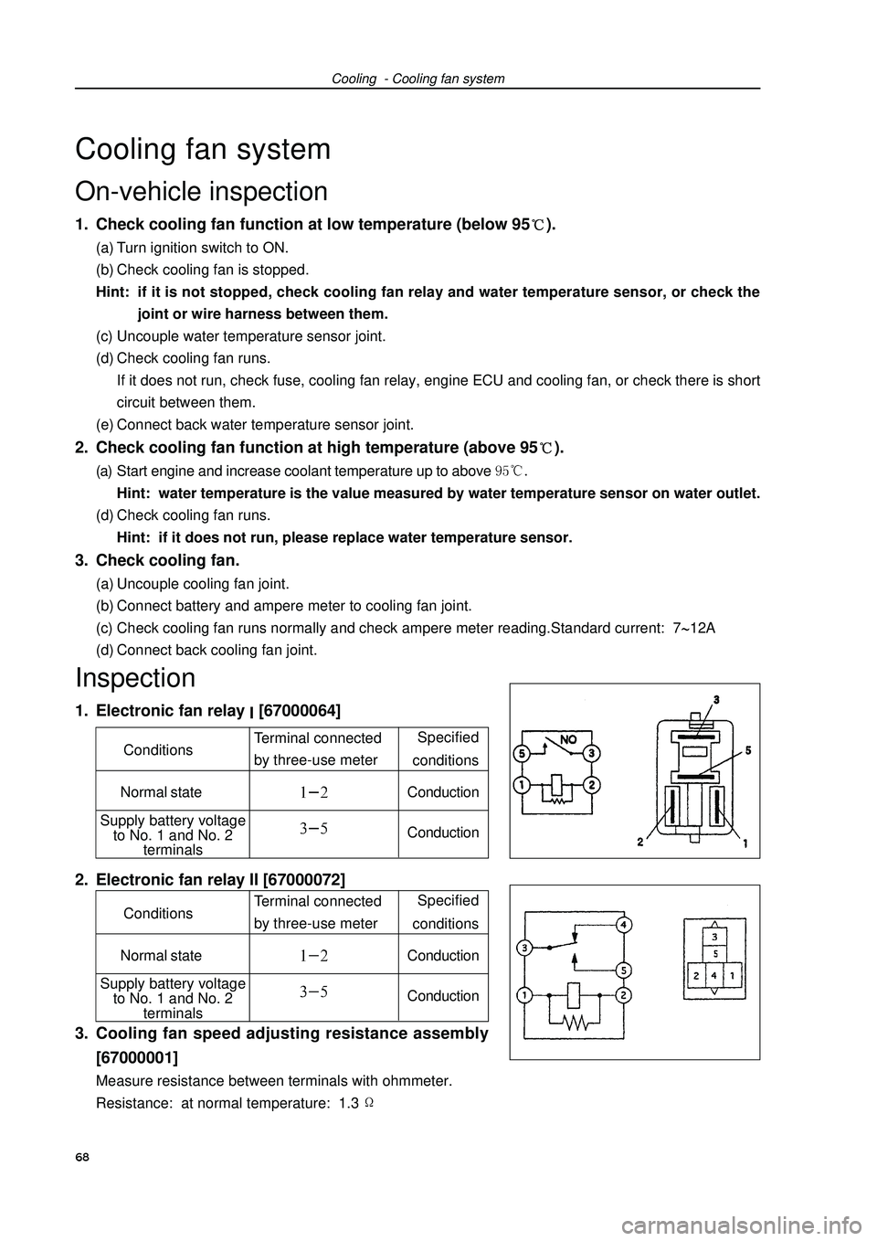
Cooling - Cooling fan systemCooling fan systemOn-vehicle inspection1. Check cooling fan function at low temperature (below 95).(a) Turn ignition switch to ON.
(b) Check cooling fan is stopped.
Hint: if it is not stopped, check cooling fan relay and water temperature sensor, or check the
joint or wire harness between them.
(c) Uncouple water temperature sensor joint.
(d) Check cooling fan runs.
If it does not run, check fuse, cooling fan relay, engine ECU and cooling fan, or check there is short
circuit between them.
(e) Connect back water temperature sensor joint.2. Check cooling fan function at high temperature (above 95).(a) Start engine and increase coolant temperature up to above Hint: water temperature is the value measured by water temperature sensor on water outlet.
(d) Check cooling fan runs.
Hint: if it does not run, please replace water temperature sensor.3. Check cooling fan.(a) Uncouple cooling fan joint.
(b) Connect battery and ampere meter to cooling fan joint.
(c) Check cooling fan runs normally and check ampere meter reading.Standard current: 712A
(d) Connect back cooling fan joint.Inspection1. Electronic fan relay [67000064]
2. Electronic fan relay II [67000072]
3. Cooling fan speed adjusting resistance assembly
[67000001]Measure resistance between terminals with ohmmeter.
Resistance: at normal temperature: 1.368 Specified
conditions
Normal stateConductionConductionTerminal connected
by three-use meter Conditions
Supply battery voltage
to No. 1 and No. 2
terminals
Specified
conditions
Normal stateConductionConductionTerminal connected
by three-use meter Conditions
Supply battery voltage
to No. 1 and No. 2
terminals
Page 88 of 419

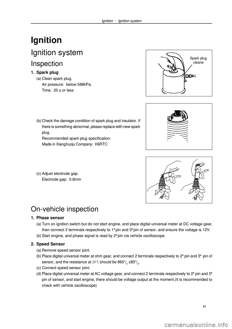
Ignition - Ignition systemSpark plug
cleaneOn-vehicle inspection1. Phase sensor(a) Turn on ignition switch but do not start engine, and place digital universal meter at DC voltage gear,
then connect 2 terminals respectively to 1# pin and 3# pin of sensor, and ensure the voltage is 12V.
(b) Start engine, and phase signal is read by 2# pin via vehicle oscilloscope.2. Speed Sensor(a) Remove speed sensor joint.
(b) Place digital universal meter at ohm gear, and connect 2 terminals respectively to 2# pin and 3# pin of
sensor, and the resistance at should be 8601/2 ±801/2.
(c) Connect speed sensor joint.
(d) Place digital universal meter at AC voltage gear, and connect 2 terminals respectively to 2# pin and 3#pin of sensor, and start engine, there should be voltage output at the moment.(It is recommended to
check with vehicle oscilloscope)IgnitionIgnition systemInspection1. Spark plug(a) Clean spark plug.
Air pressure: below 588kPa.
Time: 20 s or less
(b) Check the damage condition of spark plug and insulator. If
there is something abnormal, please replace with new spark
plug.
Recommended spark plug specification:
Made in Xianghuoju Company: K6RTC
(c) Adjust electrode gap.
Electrode gap: 0.8mm77
Page 101 of 419
Front suspension - Front shock absorber and helical spring 90Front absorber and helical springOverhaulHint: the following overhaul procedures only aim at left side (FL), and the overhaul procedures
of another side (RL) are the same as FL.1. Remove front wheels.
2. Separate front left stabilizer link assembly
[64000097].Remove nuts, and disassemble stabilizer link from absorber.
Hint: if ball joint rotates with nuts, please fix bolts with
hexagonal wrench (6mm).3. Remove front absorber and helical spring.(a) Remove bolts, and disassemble brake hose and ABS speed
sensor wire harness bracket.
(b) Remove 2 nuts and bolts under absorber.
(c) Remove 3 nuts above absorber.
(d) Remove absorber and helical spring.
Page 104 of 419
Front suspension - Front shock absorber and helical springHandling1. Handle front left absorber assembly.(a) Completely pull out absorber piston rod.
(b) As shown in the diagram, drill a small hole on cylinder body
between two lines with electric drill to make inside gas flow
out
Notes:Iron chip may fly out during drilling, please be care-
ful in operating.The gas is colorless, odorless and nontoxic.93(c) Install 2 nuts to lower end of absorber.
Torque: 15310 N.m
Hint: coat oil on thread of nuts.
(d) Install brake hose and ABS speed sensor wire harness
bracket with bolts.
Torque: 19N.m9. Install front left stabilizer link assembly [64000097].Install stabilizer link with nuts.
Torque: 745 N.m
Hint: if ball joint rotates with nuts, please fix bolts with
hexagonal wrench (6mm).10. Install front wheels.Torque: 10310 N.m11. Check and adjust front wheel alignment
(see Page 87).
Page 105 of 419

Front suspension - Lower left control arm assemblyLower left control arm assemblyReplacementHint: the replacement procedures of right side are the
same as that of left side.1. Remove front wheels.
2. Separate front left stabilizer link assembly
[64000097].Remove nuts, and disassemble stabilizer link from shock
absorber.
Hint: if ball joint rotates with nuts, please fix bolts with
hex wrench (6mm).3. Separate right side front stabilizer link assembly
[64000097].
4. Remove fixed nuts of front left drive shaft (see Page
123).
5. Separate front left wheel speed sensor assembly [67000020].
6. Separate front left brake wheel pump assembly (see Page 141).
7. Remove front left brake assembly [64000134] (see Page 142).
8. Separate left side transversal lever assembly.
9. Separate lower left control arm assembly [64000091].Remove bolts and 2 nuts, and separate lower control arm
from lower end ball joint.10. Remove front left shaft hub assembly (see Page
123).
11. Remove lower left control arm assembly
[64000091].Remove 2 bolts, nuts and lower control arm.12. Temporarily lock up lower left control arm as-
sembly [64000091].Install lower control arm, and temporarily lock up 2 bolts
and nuts.13. Install front left shaft hub assembly (see Page
123).
14. Install lower left control arm assembly [64000091].Connect lower control arm with ball joint with 2 bolts and nuts.
Torque: 14210 N.m15. Install left side transversal lever assembly. (See Page 123)
16. Install front left brake assembly. [64000134] (See Page 141)
94
Page 106 of 419
17. Install front left brake wheel pump bracket as-
sembly (see Page 141).
18. Install fixed nuts of front left drive shaft (see
Page 123).
19. Install front left stabilizer link assembly
[64000097].Install stabilizer link with nuts.
Torque: 745 N.m
Hint: if ball joint rotates with nuts, please fix bolts with
hex wrench (6mm).20. Install front right stabilizer link assembly
[64000097].Hint: the installation procedures of right side are the
same as that of left side.21. Align suspension.(a) Install front wheels and lay down vehicle from the lift.
Torque: 10310 N.m
(b) Align suspension components by means of lifting ve-
hicle several times.22. Completely lock up lower left control arm assem-
bly [64000091].Completely tighten 2 bolts and nuts.
Torque: 13710 N.m23. Check and adjust front wheel alignment
(see Page 87).
24. Check ABS sensor signal.Front suspension - Lower left control arm assembly95