Page 35 of 419
5. Check heater resistance of heated oxygen sensor.(a) Uncouple oxygen sensor joint.
(b) Place digital universal meter at ohm gear, and connect 2 terminals respectively to 1# (white) pin and
2# (black) pin, and the resistance under normal temperature is 166. Check fuel tank cover.Visually check fuel tank cover and gasket are distorted or damaged.Exhaust gas control - Exhaust gas control system 24 Oxygen sensor
Main relay
Page 38 of 419

9. Check compression pressure.(a) Warm up engine.
(b) Remove ignition coil.
(c) Remove spark plug.
(d) Check cylinder compression pressure.
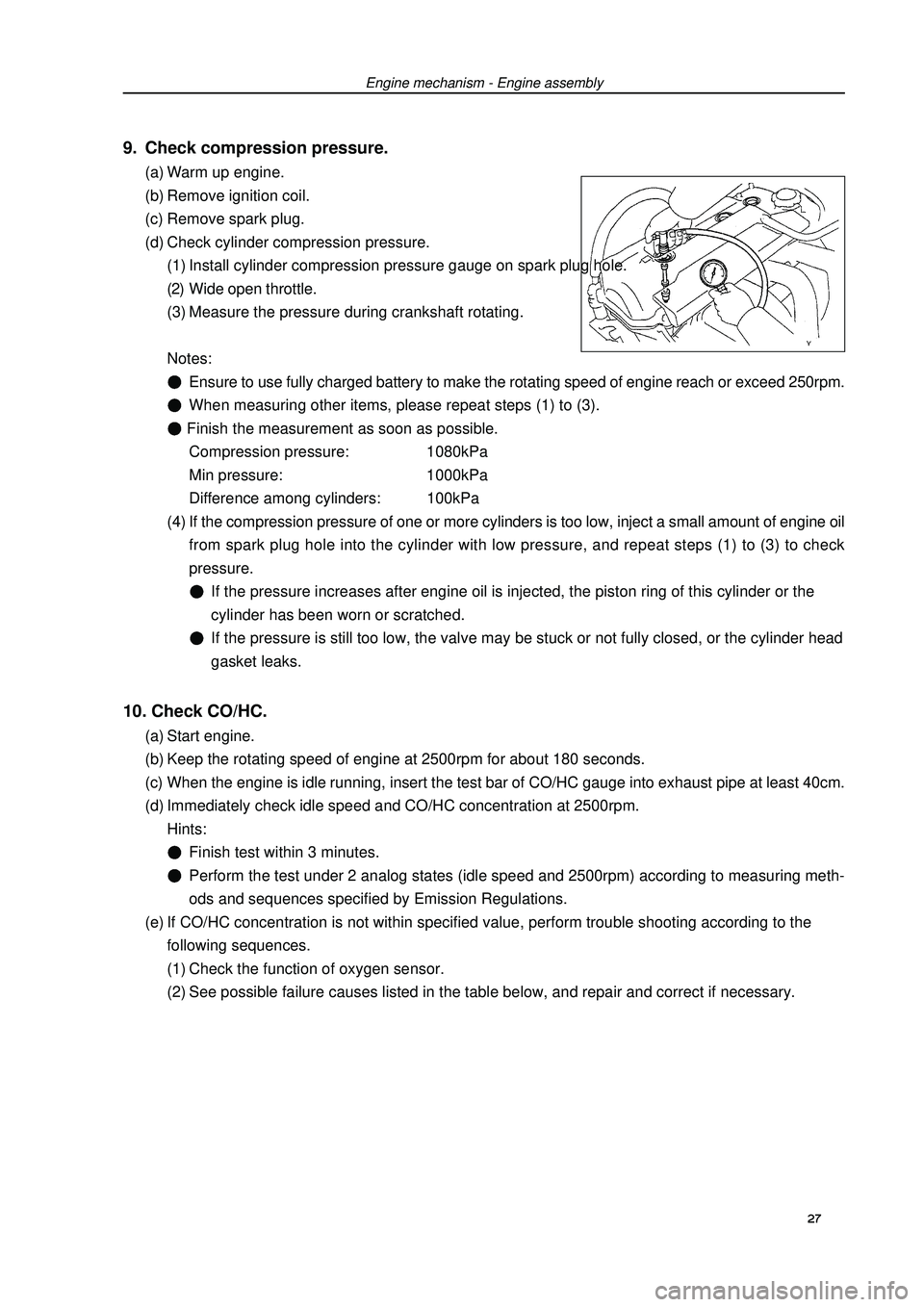
(1) Install cylinder compression pressure gauge on spark plug hole.
(2) Wide open throttle.
(3) Measure the pressure during crankshaft rotating.
Notes:Ensure to use fully charged battery to make the rotating speed of engine reach or exceed 250rpm.When measuring other items, please repeat steps (1) to (3). Finish the measurement as soon as possible.
Compression pressure: 1080kPa
Min pressure: 1000kPa
Difference among cylinders: 100kPa
(4) If the compression pressure of one or more cylinders is too low, inject a small amount of engine oil
from spark plug hole into the cylinder with low pressure, and repeat steps (1) to (3) to check
pressure.If the pressure increases after engine oil is injected, the piston ring of this cylinder or the
cylinder has been worn or scratched.If the pressure is still too low, the valve may be stuck or not fully closed, or the cylinder head
gasket leaks.10. Check CO/HC.(a) Start engine.
(b) Keep the rotating speed of engine at 2500rpm for about 180 seconds.
(c) When the engine is idle running, insert the test bar of CO/HC gauge into exhaust pipe at least 40cm.
(d) Immediately check idle speed and CO/HC concentration at 2500rpm.
Hints:Finish test within 3 minutes.Perform the test under 2 analog states (idle speed and 2500rpm) according to measuring meth-
ods and sequences specified by Emission Regulations.
(e) If CO/HC concentration is not within specified value, perform trouble shooting according to the
following sequences.
(1) Check the function of oxygen sensor.
(2) See possible failure causes listed in the table below, and repair and correct if necessary.Engine mechanism - Engine assembly27
Page 39 of 419
Engine mechanism - Engine assemblyCO HC Trouble occurrence Possible causes 28 Normal HighUnstable idle speed
Low HighUnstable idle speed
(HC readings not stable)
High HighUnstable idle speed
(black smoke emission)1. Ignition system malfunctionIgnition timing incorrect Spark plug too dirty, short circuit or clearance
incorrect
2. Valve clearance incorrect
3. Air inlet and exhaust valve leaky
4. Cylinder leaky
1. Vacuum leak:PCV hoseIntake manifoldThrottle bodyIdle speed stepping motorVacuum booster and pipelines
2. Fire caused by too thin mixing ratio
1. Air filter core blocked
2. PCV valve blocked
3. EFI system malfunctionFuel pressure regulator malfunctionWater temperature sensor malfunctionIntake pressure sensor malfunctionECU malfunctionInjection nozzle malfunctionThrottle position sensor malfunction
Page 50 of 419

34. Remove power steering pump assembly.
35. Remove sub frame together with side member.(a) Remove front engine mounting assembly and rear en-
gine mounting assembly from engine assembly.
(b) Remove sub frame assembly.36. Remove starter mounting components
[4G18-3708100].
37. Remove transmission assembly.(a) Fix crankshaft with special tool, ant then remove 6 bolts.
(b) Remove transmission assembly.38. Remove clutch assembly [4G18-1601000]
and flywheel components [4G18-1005120J].(a) Fix crankshaft with special tool, ant remove clutch
assembly at first.
(b) Then remove flywheel components.39. Remove throttlesupporting plate [4G18-1008202].
40. Remove intake manifold assembly [4G18-
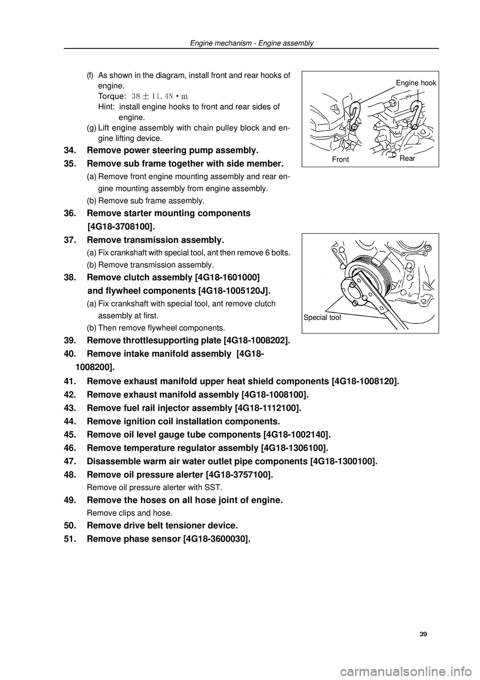
1008200].(f) As shown in the diagram, install front and rear hooks of
engine.
Torque: Hint: install engine hooks to front and rear sides of
engine.
(g) Lift engine assembly with chain pulley block and en-
gine lifting device.Engine mechanism - Engine assemblySpecial tool39 41. Remove exhaust manifold upper heat shield components [4G18-1008120].
42. Remove exhaust manifold assembly [4G18-1008100].
43. Remove fuel rail injector assembly [4G18-1112100].
44. Remove ignition coil installation components.
45. Remove oil level gauge tube components [4G18-1002140].
46. Remove temperature regulator assembly [4G18-1306100].
47. Disassemble warm air water outlet pipe components [4G18-1300100].
48. Remove oil pressure alerter [4G18-3757100].Remove oil pressure alerter with SST.49. Remove the hoses on all hose joint of engine.Remove clips and hose.50. Remove drive belt tensioner device.
51. Remove phase sensor [4G18-3600030].Engine hook
FrontRear
Page 51 of 419
![GEELY FC 2008 Workshop Manual 52. Remove speed sensor [4G18-3600010].
53. Remove knock sensor.Remove knock sensor with special tool.54. Remove water temperature sensor.Remove water temperature sensor with special tool.55. Replace GEELY FC 2008 Workshop Manual 52. Remove speed sensor [4G18-3600010].
53. Remove knock sensor.Remove knock sensor with special tool.54. Remove water temperature sensor.Remove water temperature sensor with special tool.55. Replace](/manual-img/58/57161/w960_57161-50.png)
52. Remove speed sensor [4G18-3600010].
53. Remove knock sensor.Remove knock sensor with special tool.54. Remove water temperature sensor.Remove water temperature sensor with special tool.55. Replace engine assembly.
56. Install water temperature sensor.(a) Install new gasket to water temperature sensor.
(b) Install water temperature sensor with special tool.
Torque: 57. Install knock sensor.Install knock sensor with special tool.
Torque: m58. Install speed sensor.Install speed sensor and harness clips.
Torque: 59. Install phase sensor.Torque: 60. Install drive belt tensioner device.Torque: nut: m
Bolt: m61. Install the hoses on all hose joint of engine.Install clips and hose.62. Install oil pressure alerter.(a) Clean thread of oil pressure alerter and coat adhesive.
Adhesive: anaerobic pipe thread sealing adhesive 1545
(Kesaixin 1545)
(b) Install oil pressure alerter with special tool.
Torque: 63. Install warm air water outlet pipe components.Install new gasket and warm air water outlet pipe
components.
Torque: nut: m
Bolt: Engine mechanism - Engine assembly 40
Page 56 of 419

Engine mechanism - Timing chain assemblyTiming chain assemblyReplacement1. Remove engine left bottom shield.
2. Remove engine right bottom shield.
3. Discharge coolant.
4. Remove engine plastic hood components.
5. Remove drive belt.
6. Remove power steering pump assembly.
7. Remove alternator assembly.
8. Uncouple engine wire harness.(a) Remove ignition coil joint, PS fuel pressure switch joint,
fuel line control joint and speed sensor joint.
(b) Remove bolts and nuts of fixed earth wire and put aside
engine wire harness.9. Remove ignition coil assembly.
10. Remove cylinder head cover components.(a) Remove fuel pipe retaining clip and 2 PCV hoses from
cylinder head cover.
(b) Remove 9 bolts, 2 seal washers, cylinder head cover
components and gasket.11. Remove right engine mounting assembly.(a) Remove PS oil pump reservoir and put it aside.
(b) Place wooden block between jack and engine, prop-
erly place the jack, and then remove right engine mount-
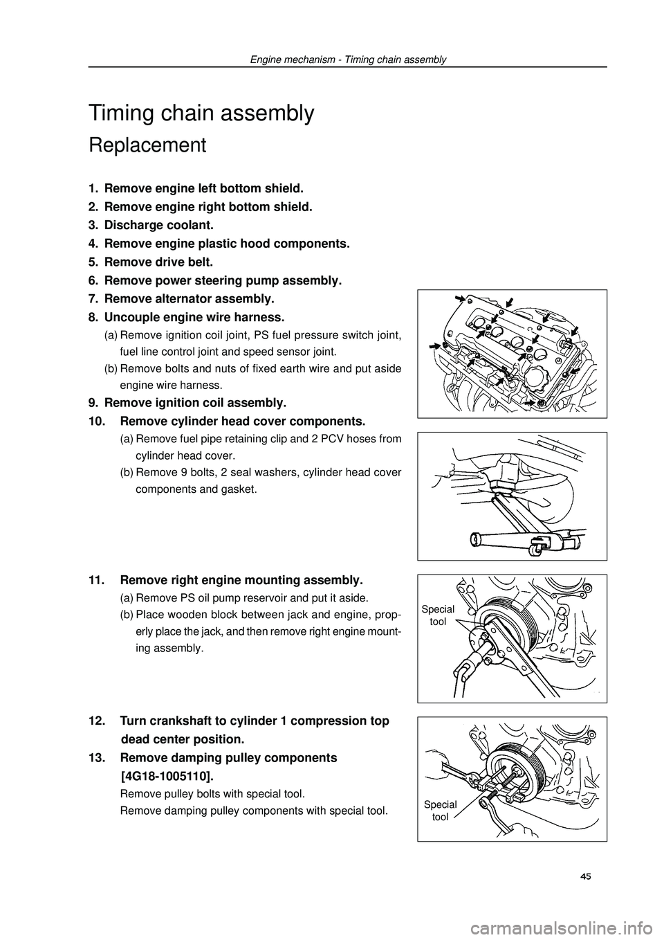
ing assembly.12. Turn crankshaft to cylinder 1 compression top
dead center position.
13. Remove damping pulley components
[4G18-1005110].Remove pulley bolts with special tool.
Remove damping pulley components with special tool.Special
tool
Special
tool45
Page 57 of 419
![GEELY FC 2008 Workshop Manual Engine mechanism - Timing chain assembly14. Remove drive belt tensioner device.Hint: operate the jack up and down to remove bolts.15. Remove water pump components [4G18-1307110].(a) Remove 6 bolts an GEELY FC 2008 Workshop Manual Engine mechanism - Timing chain assembly14. Remove drive belt tensioner device.Hint: operate the jack up and down to remove bolts.15. Remove water pump components [4G18-1307110].(a) Remove 6 bolts an](/manual-img/58/57161/w960_57161-56.png)
Engine mechanism - Timing chain assembly14. Remove drive belt tensioner device.Hint: operate the jack up and down to remove bolts.15. Remove water pump components [4G18-1307110].(a) Remove 6 bolts and water pump components.16. Remove engine stabilizer bracket on engine cross
member.
17. Remove compressor.
18. Remove speed sensor.
19. Remove chain tensioner components
[4G18-1006160].Note: do not turn crankshaft before installing chain
tensioner components.20. Remove timing chain hood components
[4G18-1006140].(a) Remove 11 bolts and nuts.
(b) Remove studs with star wrench.
(c) Pry open timing chain hood from timing chain hood pro-
trusion part between cylinder head and body with screw-
driver and remove it.
Note: be careful not to damage timing chain
hood, the contact surface of cylinder head and
body.21. Remove crankshaft front oil seal assembly
[4G18-1006150].Remove oil seal with screwdriver.22. Remove speed sensor signal panel
[4G18-3600011A].
23. Remove chain tension rail components
[4G18-1006120].
24. Remove chain guide rail components
[4G18-1006130].
25. Remove timing chain [4G18-1006110].Remove it with 2 screwdrivers.
Notes:Place a piece of cloth to protect engine.In the state of timing chain separating from timing
sprocket and turning camshaft, turn crankshaft 1/4
circle to avoid valve contacting with piston.26. Install timing chain.(a) Turn crankshaft to cylinder 1 compression top dead
center position.
(1) Turn camshaft from hexagon head part of
camshaft, and align dot marks on camshaft timing
sprocket.46
Page 58 of 419
Engine mechanism - Timing chain assembly(2) Use damping pulley bolts to turn crankshaft with its key
toward upward.
(b) Install timing chain on crankshaft timing sprocket and
align the chain link having yellow mark with timing mark
of crankshaft timing sprocket.
Hint: there are 3 yellow chain links on the timing chain.(c) Install crankshaft timing sprocket with special tool.
(d) Install timing chain on camshaft timing sprocket and
align the chain link having yellow mark with camshaft
timing sprocket.27. Install chain guide rail components.Torque: m28. Install chain tension rail components.Torque: 29. Install speed sensor signal panel.Install signal panel with “F” mark toward forward.Toward portSet key
Yellow
mark
Timing mark
Special tool
Color (yellow) mark
Timing mark 47