2008 GEELY FC sensor
[x] Cancel search: sensorPage 8 of 419

Brake
Brake system......................................................
132
Notes..............................................................
132
Remove malfunction...........................................
133
Malfunction phenomenon table.....................
133
Brake liquid.........................................................
135
Discharge the air in brake system.................
135
Brake pedal assembly........................................
136
Adjustment.....................................................
136
Change..........................................................
137
Vacuum booster assembly.................................
138
Inspection on automobile...............................
138
Change..........................................................
138
Front brake assembly.........................................
141
Overhaul........................................................
141
Rear brake assembly.........................................
144
Overhaul........................................................
144Hydraulic pressure control unit (equipping with ABS)...148
Inspection on automobile...............................
148
Change..........................................................
148
Speed sensor of front wheel..............................
151
Change..........................................................
151
Speed sensor of rear wheels...........................
152
Change..........................................................
152
Parking brake
Parking brake system.........................................
154
Malfunction phenomenon table.....................
154
Adjustment.....................................................
154
Parking brake handle assembly.........................
155
Change..........................................................
155
Parking front bake pull cable assembly............
156
Change..........................................................
156
Parking rear brake pull cable assembly...........
158
Change..........................................................
158
Parking brake assembly....................................
161
Overhaul........................................................
161Transmission
Disassemble assembly...................................
165
Assemble the assembly....................................
191
Steering column
Steering system..................................................
192
Note...............................................................
192
Malfunction phenomenon table.....................
192
Inspection on automobile...............................
193
Steering column system.....................................
194
Overhaul........................................................
194
Power steering
Power steering system......................................
198
Note...............................................................
198
Malfunction phenomenon table....................
199
Inspection on automobile.............................
200
Power steering oil pump assembly..................
203
Overhaul........................................................
203
Power steering gear assembly.........................
205
Overhaul........................................................
205
Air conditioner
Air conditioning system......................................
213
Note...............................................................
213
Inspection on automobile...............................
213
Inspection......................................................
214
Refrigerant..........................................................
215
Inspection on automobile...............................
215
Change..........................................................
221
Refrigerant pipeline............................................
222
Parts...............................................................
222Control assembly, air conditioner control panel (AUTO A/C)...223
Overhaul........................................................
223
Fan assembly...................................................
224
Overhaul........................................................
224
Air conditioner central heating core assembly..
227
Overhaul........................................................
227
Compressor assembly.....................................
234
Page 19 of 419
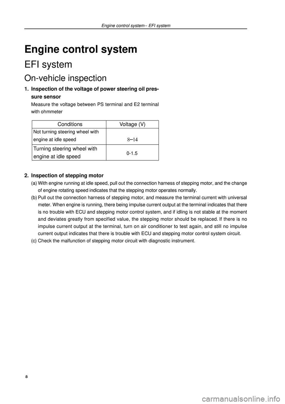
Engine control systemEFI systemOn-vehicle inspection1. Inspection of the voltage of power steering oil pres-
sure sensorMeasure the voltage between PS terminal and E2 terminal
with ohmmeter2. Inspection of stepping motor(a) With engine running at idle speed, pull out the connection harness of stepping motor, and the change
of engine rotating speed indicates that the stepping motor operates normally.
(b) Pull out the connection harness of stepping motor, and measure the terminal current with universal
meter. When engine is running, there being impulse current output at the terminal indicates that there
is no trouble with ECU and stepping motor control system, and if idling is not stable at the moment
and deviates greatly from specified value, the stepping motor should be replaced. If there is no
impulse current output at the terminal, turn on air conditioner to test again, and still no impulse
current output indicates that there is trouble with ECU and stepping motor control system circuit.
(c) Check the malfunction of stepping motor circuit with diagnostic instrument.Engine control system·- EFI system 8Conditions Voltage (V) Not turning steering wheel with
engine at idle speed Turning steering wheel with
engine at idle speed 0-1.5
Page 20 of 419
Engine control system·- EFI systemInspection1. VVT control solenoid valve assembly (4G18-1006200)(a) Resistance inspection
(1) Measure the resistance between terminals with ohmmeter
Resistance: (b) Operation inspection
Connect battery positive (+) wire to No.1 terminal and negative (-) wire to No. 2 terminal, and check
valve operation.
Note: ensure that the valve is not stuck.
Hint: if there are foreign matters in the valve, the valve could not be closed tightly and will
thus result in slight pressure being lifted toward higher direction.2. Throttle body components (4G18-1001240)(a) Inspection of throttle body
(1) Throttle valve shaft should not swing.
(2) All channels should not be blocked.
(3) Throttle valve plate should rotate flexibly and act smoothly.
(4) When the throttle is at closed position, there should be no clearance between throttle stop bolts and
throttle lever.
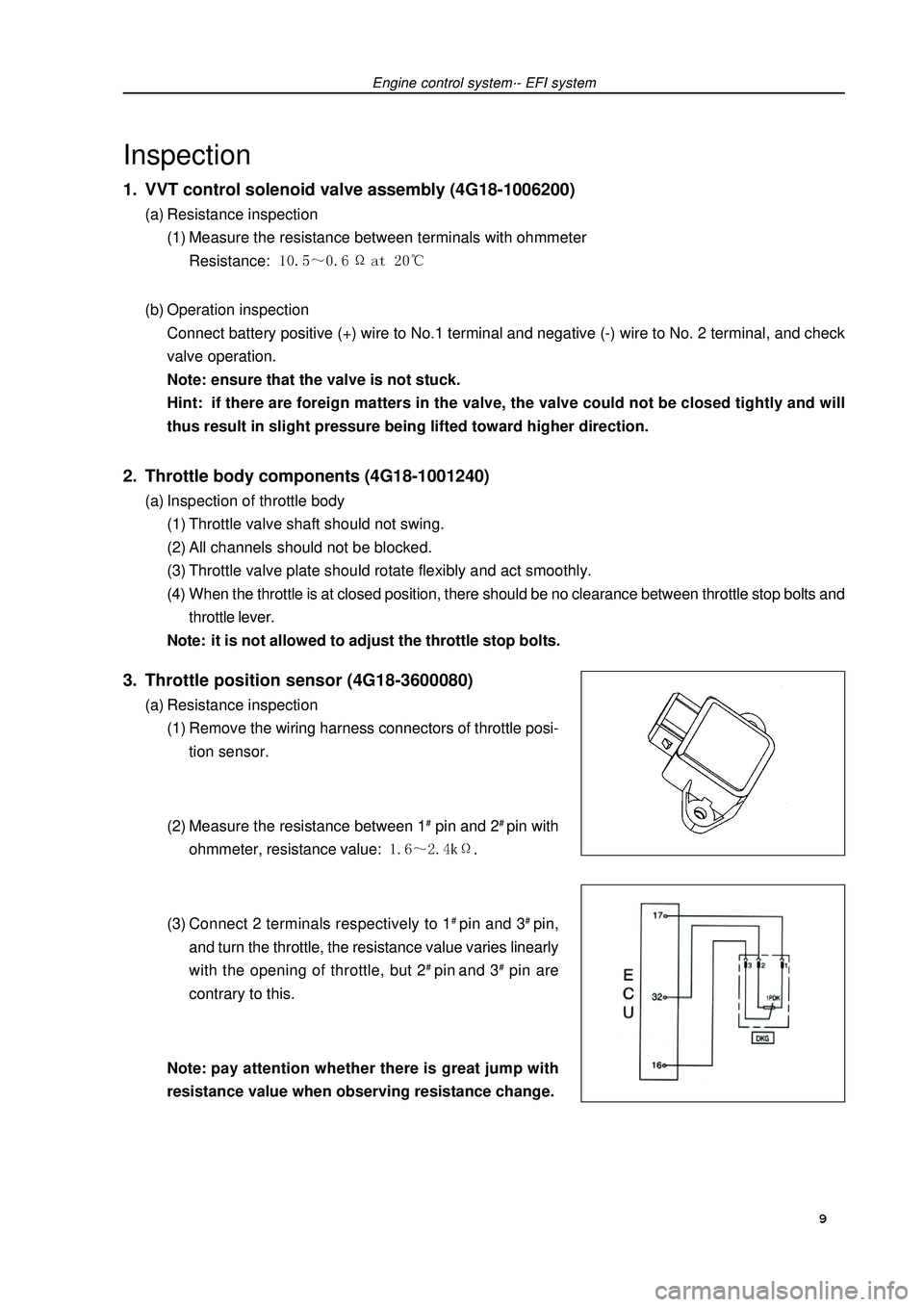
Note: it is not allowed to adjust the throttle stop bolts.3. Throttle position sensor (4G18-3600080)(a) Resistance inspection
(1) Remove the wiring harness connectors of throttle posi-
tion sensor.
(2) Measure the resistance between 1# pin and 2# pin with
ohmmeter, resistance value: .
(3) Connect 2 terminals respectively to 1# pin and 3# pin,
and turn the throttle, the resistance value varies linearly
with the opening of throttle, but 2# pin and 3# pin are
contrary to this.
Note:pay attention whether there is great jump with
resistance value when observing resistance change. 9
Page 21 of 419
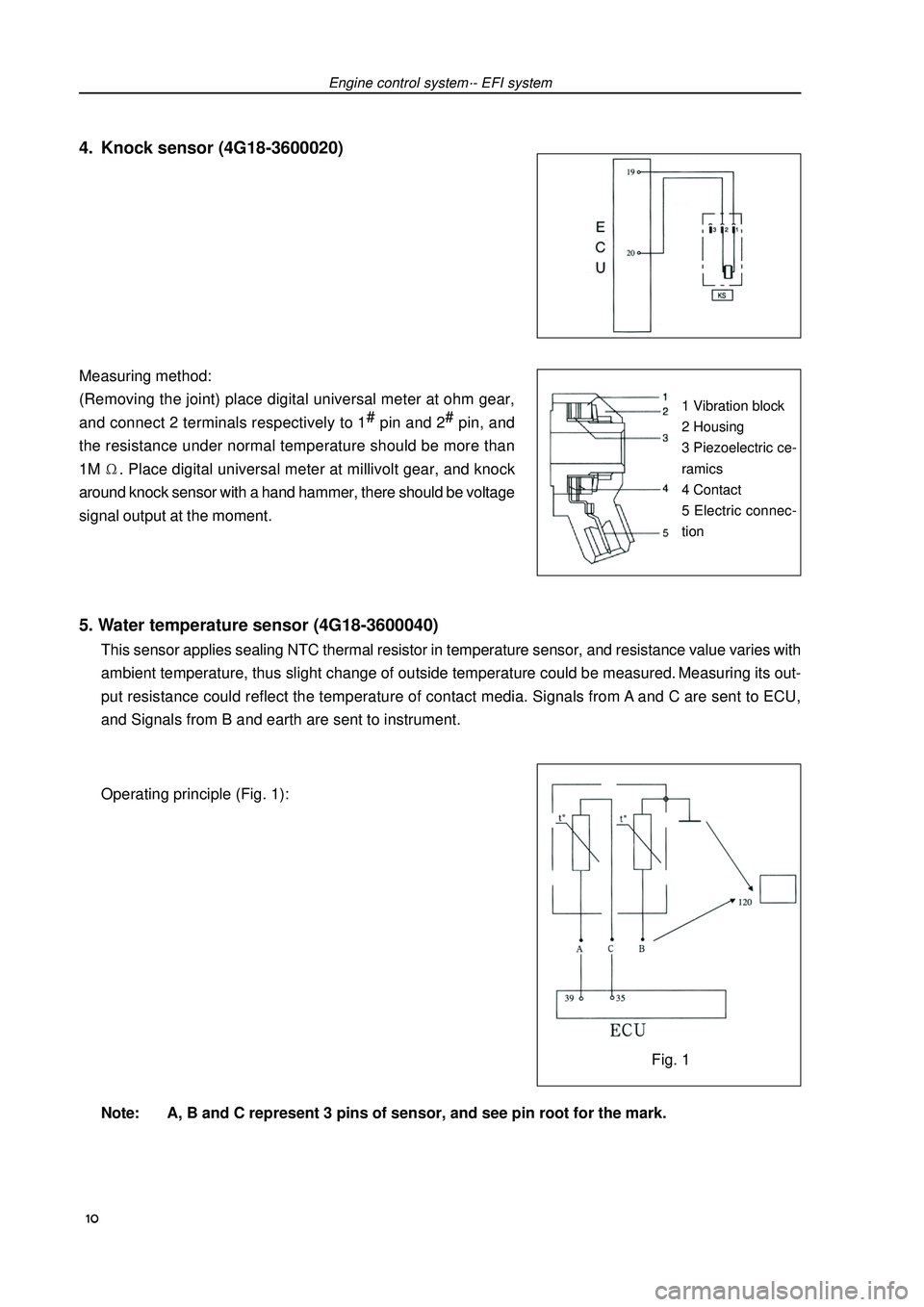
5. Water temperature sensor (4G18-3600040)This sensor applies sealing NTC thermal resistor in temperature sensor, and resistance value varies with
ambient temperature, thus slight change of outside temperature could be measured. Measuring its out-
put resistance could reflect the temperature of contact media. Signals from A and C are sent to ECU,
and Signals from B and earth are sent to instrument.
Operating principle (Fig. 1):
Note: A, B and C represent 3 pins of sensor, and see pin root for the mark. Measuring method:
(Removing the joint) place digital universal meter at ohm gear,
and connect 2 terminals respectively to 1#
pin and 2#
pin, and
the resistance under normal temperature should be more than
1M. Place digital universal meter at millivolt gear, and knock
around knock sensor with a hand hammer, there should be voltage
signal output at the moment.Engine control system·- EFI systemFig. 11 Vibration block
2 Housing
3 Piezoelectric ce-
ramics
4 Contact
5 Electric connec-
tion4. Knock sensor (4G18-3600020) 10
Page 22 of 419
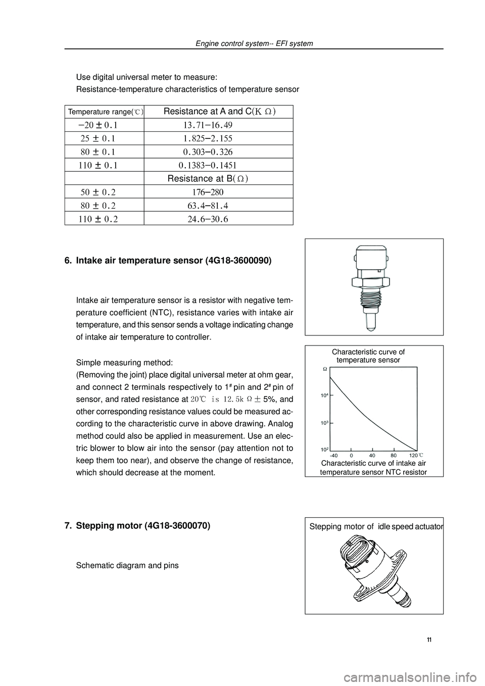
Characteristic curve of intake air
temperature sensor NTC resistorCharacteristic curve of
temperature sensorStepping motor ofidle speed actuator6. Intake air temperature sensor (4G18-3600090)Intake air temperature sensor is a resistor with negative tem-
perature coefficient (NTC), resistance varies with intake air
temperature, and this sensor sends a voltage indicating change
of intake air temperature to controller.
Simple measuring method:
(Removing the joint) place digital universal meter at ohm gear,
and connect 2 terminals respectively to 1# pin and 2# pin of
sensor, and rated resistance at 5%, and
other corresponding resistance values could be measured ac-
cording to the characteristic curve in above drawing. Analog
method could also be applied in measurement. Use an elec-
tric blower to blow air into the sensor (pay attention not to
keep them too near), and observe the change of resistance,
which should decrease at the moment.7. Stepping motor (4G18-3600070)Schematic diagram and pinsEngine control system·- EFI systemUse digital universal meter to measure:
Resistance-temperature characteristics of temperature sensor 11 Temperature range( Resistance at A and CResistance at B
Page 24 of 419
Engine control system·- Throttle body assemblyThrottle body assemblyRemoving, installing and disassembling, assembling1. Discharge coolant (see Page 73).
2. Remove air cleaner hose assembly.
3. Remove engine plastic hood components [4G18-1000310].
4. Remove throttle pull cable assembly.
5. remove throttle body assembly [4G18-1008240].(a) Uncouple throttle position sensor joint and stepping motor joint.
(b) Disassemble ventilation hose.
(c) Remove 2 bolts and throttle control pull cable bracket.
(d) Remove 2 preheating water inlet and outlet hoses of throttle.
(e) Remove 2 bolts and 2 nuts, and remove throttle body from intake air manifold.6. Remove stepping motor of throttle body [4G18-3600070].Remove 3 screws and stepping motor.7. Install stepping motor of throttle body.Install stepping motor.8. Install throttle body assembly.(a) Install new seal gasket on intake air manifold.
(b) Install throttle body, 2 bolts and 2 nuts.
Torque: 9. Refill coolant.
10.Check there is leakage with coolant.
13
Page 32 of 419
Fuel - Fuel tank assemblyFuel tank assembly1. Take measures to prevent gasoline leaking
(see Page 14)
2. Remove rear seat cushion assembly
3. Remove rear floor repairing hole cover
4. Remove No. 2 fuel evaporation assembly
5. Remove fuel tank main fuel hose and oil return pipe
assembly
6. Remove fuel pump assembly
7. Discharge fuel
8. Remove front floor bracket
9. Remove front exhaust pipe assembly(a) Move away carpet and remove oxygen sensor joint.
(b) Remove front exhaust pipe assembly10.Disassemble the vent pipe of fuel hose
11.Disassemble filler pipe from fuel tank
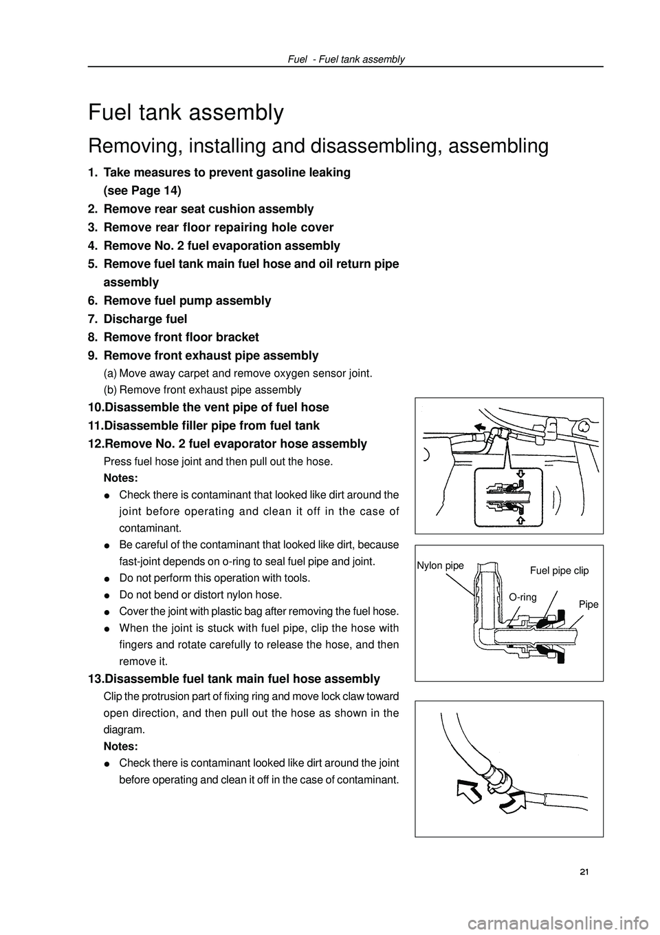
12.Remove No. 2 fuel evaporator hose assemblyPress fuel hose joint and then pull out the hose.
Notes:Check there is contaminant that looked like dirt around the
joint before operating and clean it off in the case of
contaminant.Be careful of the contaminant that looked like dirt, because
fast-joint depends on o-ring to seal fuel pipe and joint.Do not perform this operation with tools.Do not bend or distort nylon hose.Cover the joint with plastic bag after removing the fuel hose.When the joint is stuck with fuel pipe, clip the hose with
fingers and rotate carefully to release the hose, and then
remove it.13.Disassemble fuel tank main fuel hose assemblyClip the protrusion part of fixing ring and move lock claw toward
open direction, and then pull out the hose as shown in the
diagram.
Notes:Check there is contaminant looked like dirt around the joint
before operating and clean it off in the case of contaminant. 21 Removing, installing and disassembling, assemblingFuel pipe clipNylon pipeO-ring
Pipe
Page 34 of 419
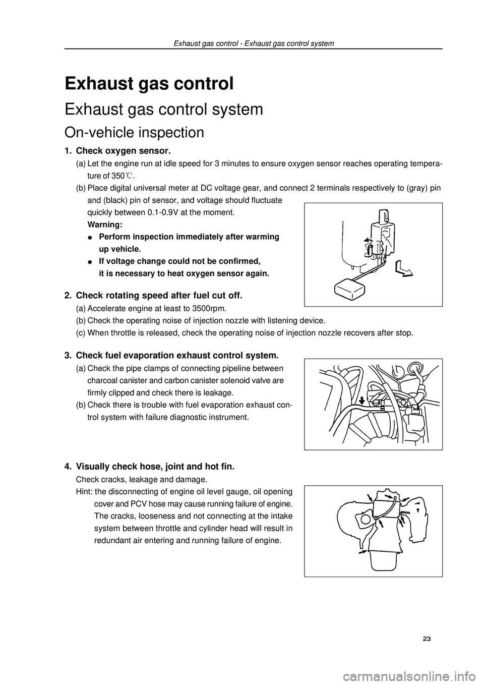
Exhaust gas controlExhaust gas control systemOn-vehicle inspection1. Check oxygen sensor.(a) Let the engine run at idle speed for 3 minutes to ensure oxygen sensor reaches operating tempera-
ture of 350(b) Place digital universal meter at DC voltage gear, and connect 2 terminals respectively to (gray) pin
and (black) pin of sensor, and voltage should fluctuate
quickly between 0.1-0.9V at the moment.
Warning:Perform inspection immediately after warming
up vehicle.If voltage change could not be confirmed,
it is necessary to heat oxygen sensor again.Exhaust gas control - Exhaust gas control system2. Check rotating speed after fuel cut off.(a) Accelerate engine at least to 3500rpm.
(b) Check the operating noise of injection nozzle with listening device.
(c) When throttle is released, check the operating noise of injection nozzle recovers after stop.3. Check fuel evaporation exhaust control system.(a) Check the pipe clamps of connecting pipeline between
charcoal canister and carbon canister solenoid valve are
firmly clipped and check there is leakage.
(b) Check there is trouble with fuel evaporation exhaust con-
trol system with failure diagnostic instrument.4. Visually check hose, joint and hot fin.Check cracks, leakage and damage.
Hint: the disconnecting of engine oil level gauge, oil opening
cover and PCV hose may cause running failure of engine.
The cracks, looseness and not connecting at the intake
system between throttle and cylinder head will result in
redundant air entering and running failure of engine.23