Page 146 of 392

139Chapter 9 Brake SystemSection 1 Brake SystemPrecaution1. It's very important to keep the parts and area clean when repairing the brake system.
2. Care must be taken to replace each part properly as it could affect the performance of the brake
system and result in a driving hazard.
3. Do not let brake fluid remain on a painted surface when repairing any parts. Wash it off
immediately.
4. If any work is done on the brake system or air in the brake pipelines is suspected, bleed the
system of air.
5. Check the brake system for leakage after repairing the brake system.
6. Use specified brake fluid. Do not mix with other brand of brake fluid.Problem symptoms tableUse the table below to help you find the cause of the problem. The numbers indicate the priority of the likely
cause of the problem. Check each part in order. If necessary, replace these parts.Symptom Cause
1. Brake system (fluid leaks)
2. Brake system (air in)
3. P iston Cup in Sub-pump (worn or dama ge d)
4. Rear brake shoe clearance (out of adjustment)
5. Master cylinder (faulty)
6. Booste r push rod (out of a djustme nt)
7. Brake shoe or lining (oily)
8. Disc/Drum scratched
1. Brake pe dal free stroke is too small
2. P a rking brake le ver stroke (out of a djustme nt)
3. P a rking brake ca ble (stic king)
4. Rear brake shoe clearance (out of adjustment)
5. Brake pa d or lining (c rac ked or distorte d)
6. Wheel cylinder piston (stuck or frozen)
7. Return spring (faulty)
8. Va cuum booster (faulty)
9. Brake master cylinder (faulty) Low Brake P edal
Brake Stagnation
Page 147 of 392

140Section 2 Brake FluidBleeding1. Fill brake reservoir with brake fluid
Brake fluid: JG4 GB10830
2. Bleed brake pipeline system
(1) Connect the vinyl pipe to the wheel cylinder bleeder plug port
(2) Depress the brake pedal several times, and then loosen the bleeder plug with the pedal held down.
(3) At the point when fluid stops flowing out, tighten the bleeder plug, and then release the brake pedal.
(4) Repeat (2) and (3) until all the air in the fluid has been bled out.
(5) Repeat the above procedure to bleed the brake pipeline of the air for each wheel cylinder.
Notice: Fill brake fluid into the reservoir all the time when bleeding.
3. Check fluid level in reservoir
Check the fluid level and fill fluid if necessary.Symptom Suspe ct a re a
1. Whee l cylinder piston (stuck)
2. Bra ke shoe lining (oily)
3. Disc (scratched)
4. Bra ke shoe s or lining (c ra cke d or distorte d)
5. Whee l hub be a ring (worn or da mage d)
Tire pressure (not as specified)
1. Bra ke shoe lining (da mage d)
2. Insta lla tion bolt (loose )
3. Disc (scratched)
4. Bra ke shoe (ba d in qua lity)
5. Bra ke shoe s lining (oily)
6. Sound isolating shim da mage d
7. Hold spring of bra ke shoe (da mage ) Brake Deviation
Noise from brake
Page 152 of 392

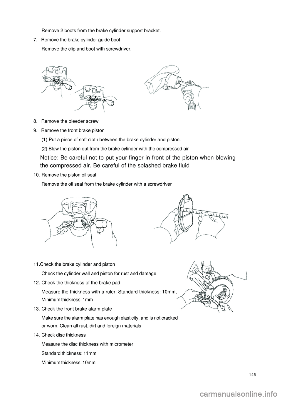
145Remove 2 boots from the brake cylinder support bracket.
7. Remove the brake cylinder guide boot
Remove the clip and boot with screwdriver.
8. Remove the bleeder screw
9. Remove the front brake piston
(1) Put a piece of soft cloth between the brake cylinder and piston.
(2) Blow the piston out from the brake cylinder with the compressed air
Notice: Be careful not to put your finger in front of the piston when blowing
the compressed air. Be careful of the splashed brake fluid
10. Remove the piston oil seal
Remove the oil seal from the brake cylinder with a screwdriver
11.Check the brake cylinder and piston
Check the cylinder wall and piston for rust and damage
12. Check the thickness of the brake pad
Measure the thickness with a ruler: Standard thickness: 10mm,
Minimum thickness: 1mm
13. Check the front brake alarm plate
Make sure the alarm plate has enough elasticity, and is not cracked
or worn. Clean all rust, dirt and foreign materials
14. Check disc thickness
Measure the disc thickness with micrometer:
Standard thickness: 11mm
Minimum thickness: 10mm
Page 153 of 392

14615. Remove the front disc
16. Installation is in the reverse order of the above-mentioned procedure
Notice:
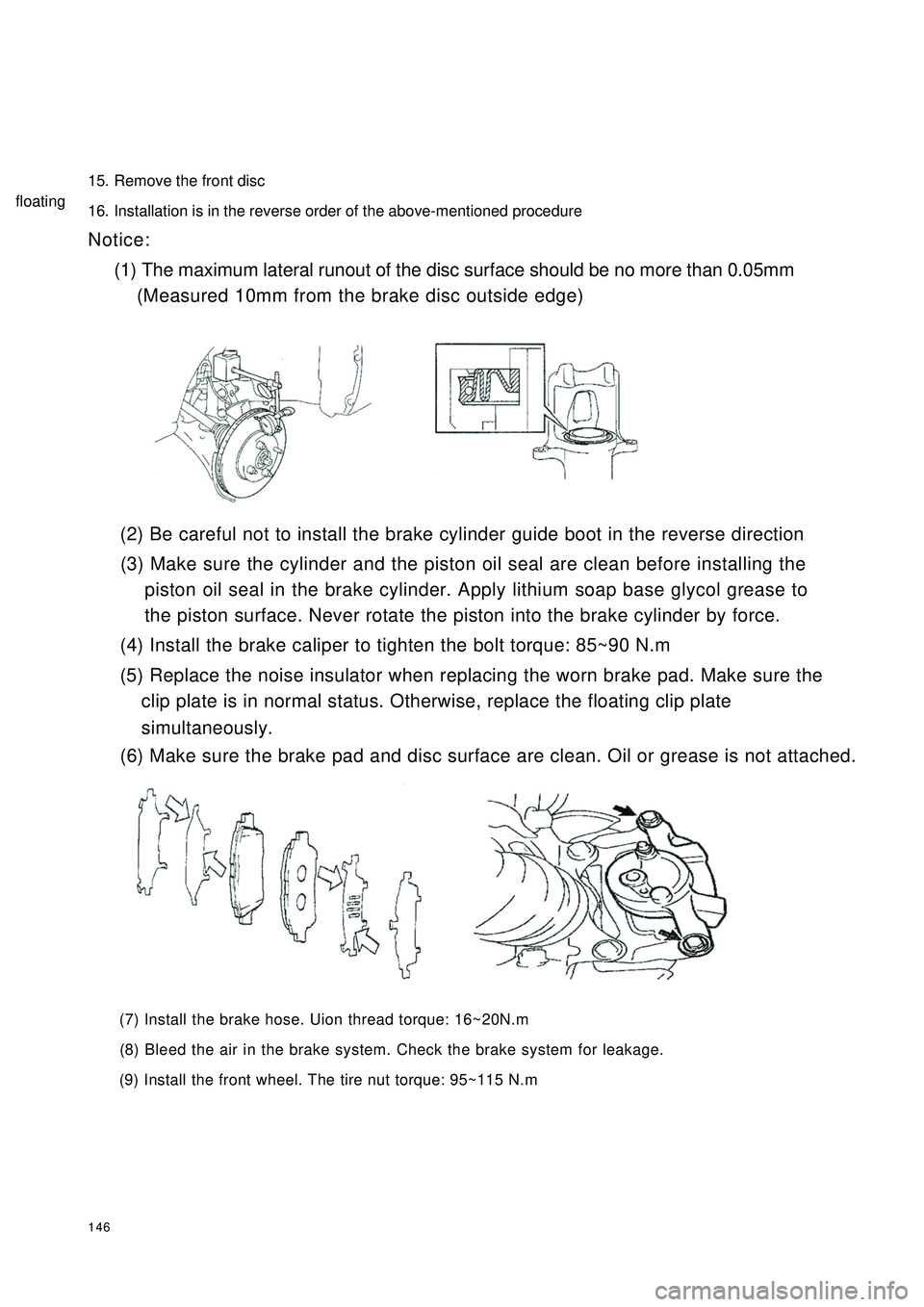
(1) The maximum lateral runout of the disc surface should be no more than 0.05mm
(Measured 10mm from the brake disc outside edge)
(2) Be careful not to install the brake cylinder guide boot in the reverse direction
(3) Make sure the cylinder and the piston oil seal are clean before installing the
piston oil seal in the brake cylinder. Apply lithium soap base glycol grease to
the piston surface. Never rotate the piston into the brake cylinder by force.
(4) Install the brake caliper to tighten the bolt torque: 85~90 N.m
(5) Replace the noise insulator when replacing the worn brake pad. Make sure the
clip plate is in normal status. Otherwise, replace the floating clip plate
(6) Make sure the brake pad and disc surface are clean. Oil or grease is not attached.
(7) Install the brake hose. Uion thread torque: 16~20N.m
(8) Bleed the air in the brake system. Check the brake system for leakage.
(9) Install the front wheel. The tire nut torque: 95~115 N.msimultaneously.floating
Page 154 of 392
147Section 6 Rear BrakeComponents
Repairing1. Remove rear wheel
2. Drain the brake fluid
3. Remove the brake drum
(1) loose the parking brake handle
(2) Remove the cotter pin with a long nose pliers
(3) loose the spindle slot nut
Lower Return Spring
Oil Baffle Plate
Anchor Plate
Brake Bottom Plates
Left Cable Plate
Left Torsion Spring
Adjusting Pawl Shaft
Pin
Left Adjusting
Pawl
Left Adjusting
Plate
Brake Shoe I
Wheel Hub Bearing II
Rear Spindle Cap
Wheel Hub
Bearing I
Stop Washer
Wheel Hub
Bolt
Rear Ring Gear
Rear Brake Drum
Rear Spindle Cover
Brake Shoe I
Shoe Guide
Friction Shoe
Boot
Cup
Piston
Wheel Cylinder
Spring
Piston
BootCup
Parking Brake
Left Swing Arm
Rear Brake
Auto
Adjusting Lever
Adjusting Lever Spring
Return Spring
Page 168 of 392
161Chapter 2 Starting and Charging SystemSection 1 Starting System
(MR479Q MR479QA MR481QA)I. STARTER INSPECTIONNOTICE:
These tests must be done within 5 seconds to avoid burning out the coil.
1. INSPECT MAGNETIC SWITCH
(a) Use wire to connect the starter as shown.
(b) Connect the magnetic switch and the battery as
shown.
(c) Disconnect the magnet exciting coil from the
terminal A.
(d) Check if the clutch pinion gear is moving out.
If the clutch pinion gear is not moving out, replace
the magnetic switch.
(e) Connect the battery as shown above. Disconnect
the battery positive (+) from the terminal, to make the clutch pinion gear disengaged.
(f) Check if the clutch pinion gear has returned.
If the clutch pinion gear has not returned, replace
the magnetic switch.Terminal ABatteryBatteryDisconnect
Page 169 of 392
1622. INSPECT STARTER NO-LOAD
(a) Connect the magnet exciting coil and the terminal.
(b) Connect the ammeter and the battery to the starter
as shown.
(c) Check that the starter rotates smoothly and steadily
with the clutch pinion gear moving out.
(d) Check that the ammeter shows the specified
current.
Specified current: 90 A or less at 11.5 V
if the current is not normal, replace the starter.
3. WIRING
(a) Check that the connecting wire between
the positive (+) and the starter is stable
and reliable, and the insulating bush is in
good condition, in order to avoid a fire
caused by electric spark.
(b) Check that there is continuity in the wire
and if the insulating bush is not damaged.
If the harness is damaged, replace it.AmmeterIgnition SwitchBattery Main Fuse BoxStarter
Page 178 of 392
171Chapter 3 Combination Meter SystemSection 1 Circuit Diagram of Combination Meter and Location of
Multi-pin Plug-in TerminalI. CIRCUIT DIAGRAM OF CONBINATION METERSpeed Signal
Ground The Sensor
Revolution SignalWater Temperature SignaFuel Level GaugeTachometer
SpeedometerWater
Temperature Gauge
Feul Level Gauge
OdometerHigh Beam Lamp
Rear Defrost Lamp
Rear Defog Lamp
Backlight
Water Temperature WarningPower Steering
Fuel WarningCharge
Brake Fluid
Oil Pressure
Engine Malfunction
Driver's seat belt
Park Brake
SRS(main)
SRS(sub)