2008 GEELY CK oil
[x] Cancel search: oilPage 319 of 392

312Introduction Of The Refrigeration Pipeline Installation:
1. It is recommended to fill some SW-100 compressor oil into the refrigerating circulation when installing a
new refrigeration pipe or cooling hose.
Refill: (approximate)
5ml{5 cc}: Refrigeration pipe
10ml{10 cc}: Condenser hose
2. Fill compressor oil to O-ring and other connecting points.
3. Tighten the connecting points.
Nuts union or slider joint type:
1. Tighten the nuts or the bolts of the connectiong
points by hand.
2. Tighten the connecting points with specified
torque wrench. It is connected with nuts. Tighten
the nuts with a wrench or a torque wrench.
3. Clip the slider block recess with pliers or other
similar tool and clamp the pipe used to connect
slider block. Tighten the bolt or the nuts at the
connecting points with a torque wrench.
7. A/C control panel removal / installation:
1. Disconnect the negative (--) terminal cable from the battery.
2. Remove the auxiliary console.
3. Disconnect the hot and cold air cable and airflow allocating cable.
4. Remove A/C control panel.
5. Disconnect blower switch connector.
6. Remove the lighting wire harness connector.
7. Remove the inside and outside circulation switch connector.
8. The installation is in the reverse order of the removal.Slider BuldgeSlider RecessionTorque Wrench
Page 320 of 392

313Section 7 A/C System Faults Check & TroubleshootingI. A/C System Faults CheckInspection shall be made to isolate the fault area and its cause when the fault of A/C system occurs, and then
specific service could be performed. Inspect the whole system before re-using A/C system after a long term
of storage.
First step is initial inspection by direct "see, listen and touch". Test the system with the leak detector if
necessary.
1. Check the Refrigeration System
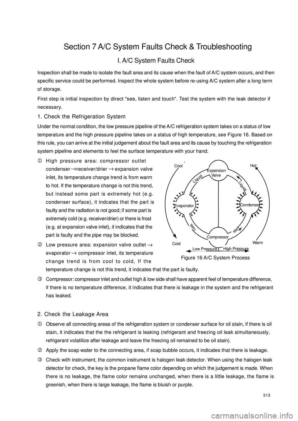
Under the normal condition, the low pressure pipeline of the A/C refrigeration system takes on a status of lowtemperature and the high pressure pipeline takes on a status of high temperature, see Figure 16. Based onthis rule, you can arrive at the initial judgement about the fault area and its cause by touching the refrigeration
system pipeline and elements to feel the surface temperature with your hand.
1High pressure area: compressor outlet
condenser receiver/drier expansion valve
inlet, its temperature change trend is from warm
to hot. If the temperature change is not this trend,
but instead some part is extremely hot (e.g.
condenser surface), it indcates that the part is
faulty and the radiation is not good; if some part is
extremely cold (e.g. receiver/drier) or there is frost
(e.g. at expansion valve inlet), it indicates that the
part is faulty and the pipe may be blocked.
2Low pressure area: expansion valve outlet
evaporator compressor inlet, its temperature
change trend is from cool to cold, If the
temperature change is not this trend, it indcates that the part is faulty.
3Compressor: compressor inlet and outlet high & low side shall have apparent feel of temperature difference,
if there is no temperature difference, it indicates that there is leakage in the system and the refrigerant
has leaked.
2. Check the Leakage Area
1Observe all connecting areas of the refrigeration system or condenser surface for oil stain, if there is oil
stain, it indicates that the the refrigerant is leaking (refrigerant and freezing oil leak simultaneously,
refrigerant volatilize after leakage and leave the freezing oil remained to be oil stain).
2Apply the soap water to the connecting area, if soap bubble occurs, it indicates that there is leakage.
3Check with instrument, the common instrument is halogen leak detector. When using the halogen leak
detector for check, the key is the propane flame color depending on which the judgement is made. When
there is no leakage, the flame color remains unchanged, when there is a little leakage, the flame is
greenish, when there is large leakage, the flame is bluish or purple.CoolColdHotWarmExpension
Va l v eCompressorEvaporator Condenser Gas
GasLiquid LiquidLow PressureHigh PressureFigure 16 A/C System Process → →
→→
Page 321 of 392

314Have a focus inspection on the following area:
a. Each pipe union joint and valve connection.
b. All hose, especially near the pipe union.
c. Compressor shaft seal, front and rear cover, gasket, oil fill plug.
d. Area on the surface of the condenser and evaporator that is scratched, bruised or damaged.
e. Expansion valve inlet and outlet connection and temperature sensor element and the welding position.
3. Check the Refrigerant
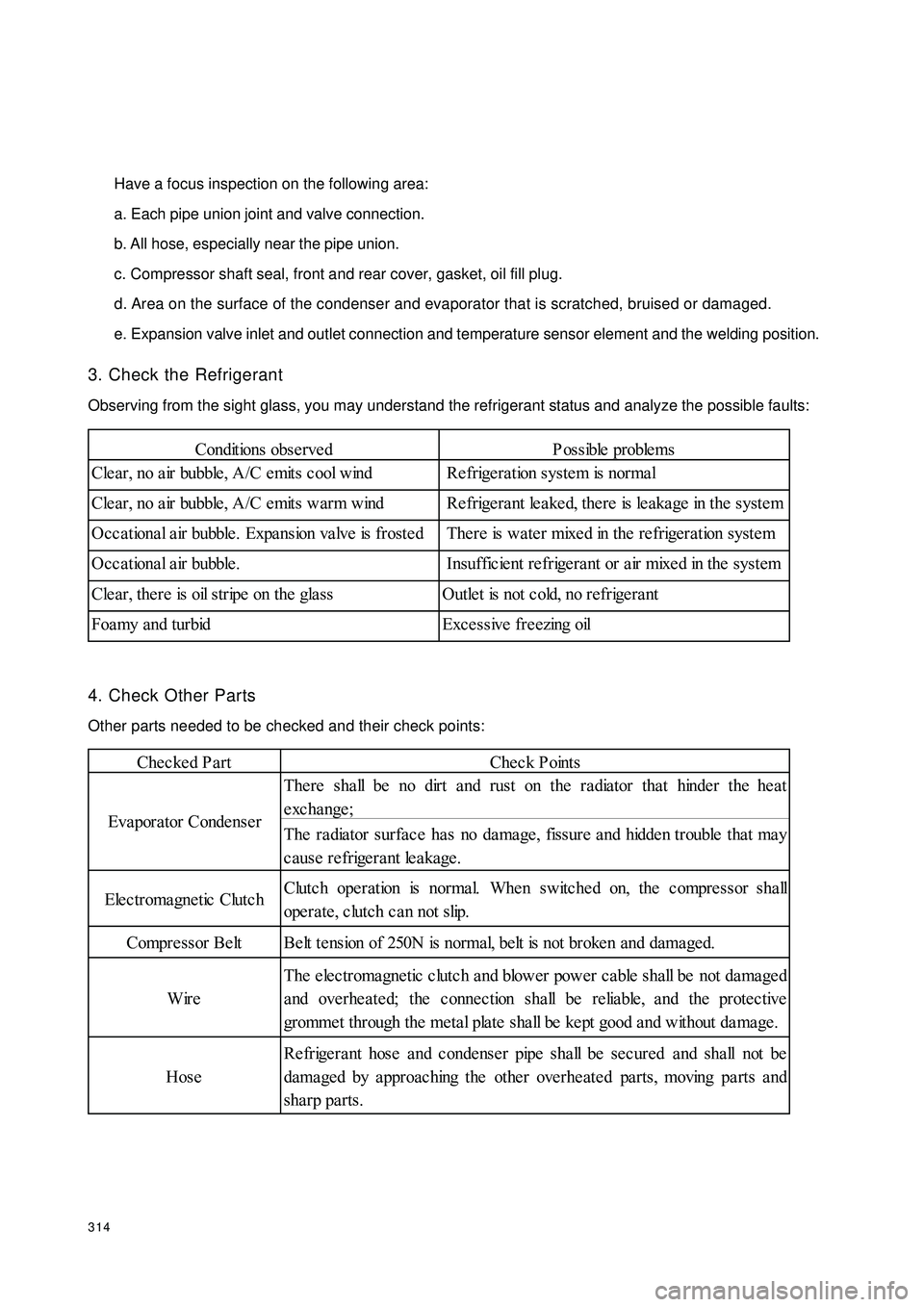
Observing from the sight glass, you may understand the refrigerant status and analyze the possible faults:
4. Check Other Parts
Other parts needed to be checked and their check points:Conditions obse rvedP ossible proble ms
Cle ar, no a ir bubble , A/C e mits c ool wind Re frige ra tion system is normal
Cle ar, no a ir bubble , A/C e mits warm wind Re frige ra nt le a ke d, the re is le aka ge in the syste m
Occ a tiona l a ir bubble . Expa nsion va lve is froste d There is wa te r mixe d in the re frigeration syste m
Occational air bubble. Insufficient refrigerant or air mixed in the system
Cle ar, the re is oil stripe on the gla ss Outle t is not c old, no refrige ra nt
Foamy and turbid Excessive freezing oilChecked PartCheck Points
The re sha ll be no dirt and rust on the radiator tha t hinde r the he at
exchange;
The ra dia tor surfa ce ha s no da mage , fissure a nd hidde n trouble tha t ma y
cause refrigerant leakage.
Elec tromagne tic Clutc hClutc h ope ration is norma l. Whe n switche d on, the c ompre ssor sha ll
operate, clutch can not slip.
Compre ssor Be lt Be lt te nsion of 250N is normal, belt is not broke n and dama ged.
WireThe electromagnetic clutch and blower power cable shall be not damaged
and overheated; the connection shall be reliable, and the protective
gromme t through the me tal plate sha ll be ke pt good a nd without da ma ge .
HoseRefrigerant hose and condenser pipe shall be secured and shall not be
dama ged by a pproac hing the othe r ove rhe ate d pa rts, moving pa rts a nd
sha rp parts. Eva pora tor Conde nse r
Page 322 of 392

315II. A/C System Diagnosis and TroubleshootingTable 1 Abnormal high pressure of the high pressure pipelineAbnormal low pressure of the high pressure pipeline Abnormal high pressure of the low pressure pipelineAbnormal low pressure of the low pressure pipelineHigh and low pressure can not be establishedSight glass has air bubble Compressor inlet side is frosted Compressor noise Abnormal heating on the compressorEvaporator is frostedDrier filter ices up A/C does not refrigerate or the cold air is insufficient× × × × Excessive refill of refrigerantDrain p rop er amount of
refrigerant
× × × × T oo lit t le refill of refrigerantRep air t he gas leak area, refill
p rop er amount of refrigerant
× × × × Refrigerant is leaked allRep air t he gas leak area, refill
p rop er amount of refrigerant
×× ××× ×T here is non-clot t ed gas in
the sy stemLoos en receiver and
condenser inlet connect or,
discharge t he non-clot t ed gas
××Excessive freez ing oil in t he
sy stemCheck comp ressor freez ing
oil level, adjus t it
× Excessive high t emp erat ure
of condenser inletPerform t he check at t he
p lace w it h good vent ilat ion
T here is dus t in t he
condens er core, air channel
w it hin t he condens er is
blocked or suffocat edU s e comp res s ed air or w at er
t o flush and remove t he dirt
on t he condenser
Condenser fan faulty or
brokenCheck the wiring status and
t he fan mot or, correct or
rep lace it
×× Exces s ively low t emp erat ure
of condenser inletStop the op eration of the
refrigerat ion sy st em
× × × Drier blocked Clean
A ir channel in t he evap orat or
blocked or suffocat edRemove t he dirt on t he
evap orat or
Evap orat or fan fault , p oor
blower mot or w ire connect ionCheck the wiring status and
t he fan mot or, correct or
rep lace it
×× ×T here is dirt in evap orat or
coreU s e t he comp res s ed air t o
clean t he evap orat or core × ×
××××
× P roblem Sy mp t om
Possible Cause T roubleshoot ing
×
Page 324 of 392

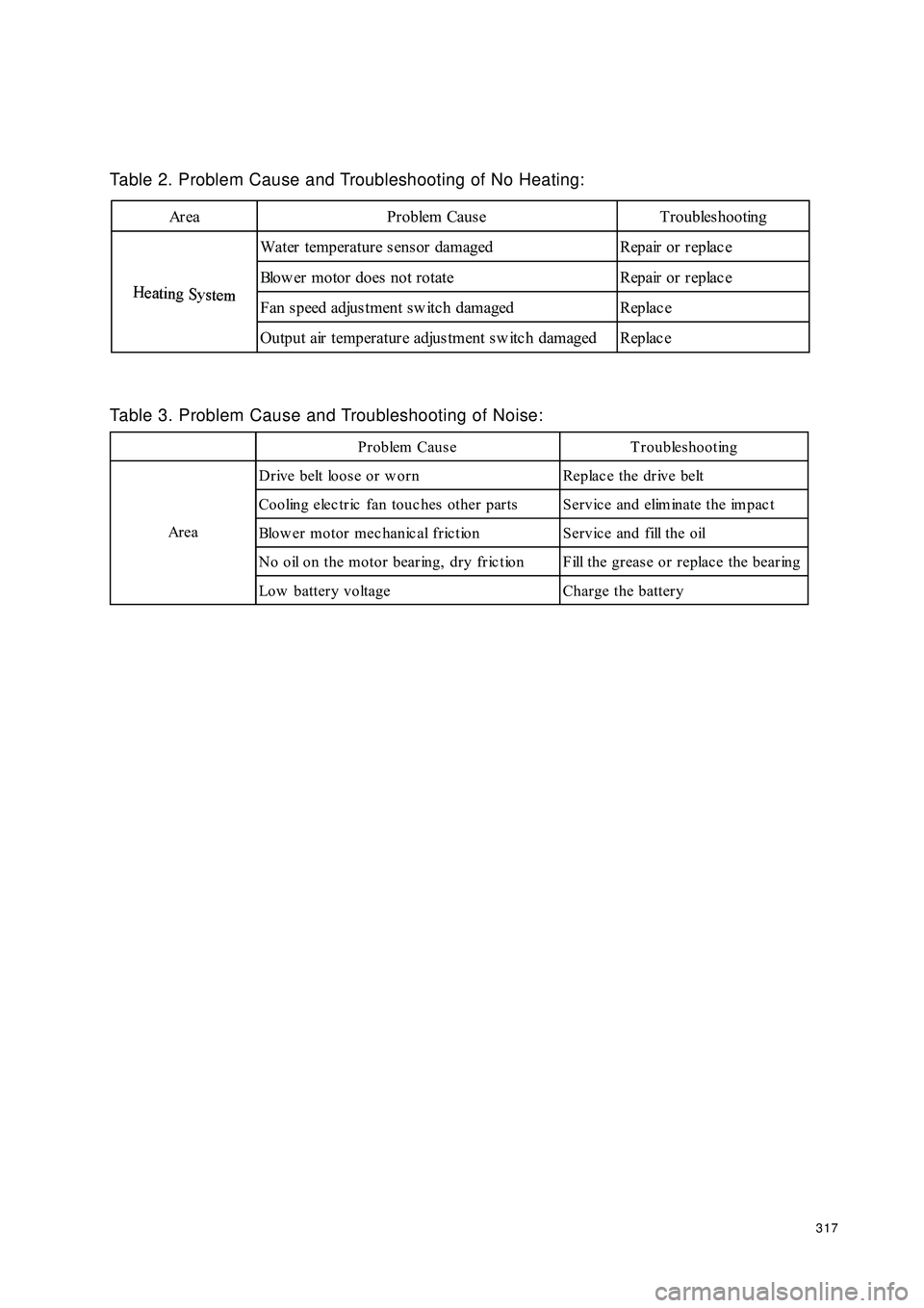
317Table 2. Problem Cause and Troubleshooting of No Heating:Area Problem Cause TroubleshootingH
eat
i
ng
Sy
st
emWater temperature sensor damaged Repair or replac e
Blow er motor does not rotate Repair or replac e
Fan s peed adjus tment sw itc h damaged Replac e
Output air temperature adjustment sw itc h damaged Replac eH
eat
i
ng
Sy
st
emTable 3. Problem Cause and Troubleshooting of Noise:Problem Cause Troubleshooting
Drive belt loose or w orn Replac e the drive belt
Cooling electric fan touc hes other parts Service and eliminate the impac t
Blow er motor mec hanic al fric tion Servic e and fill the oil
N o o il o n t h e m o t o r b e a r in g , d r y f r ic t io n F ill t h e g r e a s e o r r e p la c e t h e b e a r in g
Low battery voltage Charge the battery Ar e a
Page 334 of 392

327(IV) Rear trunk LidComponent View:
1.Rear trunk Lid Hinge Pin 2.Rear trunk Lid Hinge Retainer3.Rear trunk Lid Hinge Retainer
Mounting Nut4.Rear trunk Door Hinge Cushion 5.Rear trunk Lid Outer Panel And Reinforcement
Assembly 6.Geely Logo7.Rear License Plate Assembly8.Rear License Plate Assembly
Mounting Nut9.Rear trunk Lid Weatherstrip10.Rear trunk Lid inside Trim Board 11.Rear
trunk Lid Cushion12.Rear trunk Door Lock Cylinder Assembly 13.Rear trunk Lid inside Trim Board Clip
14.Rear trunk Lid Hinge Attaching Bolt 15.Rear trunk Door Lock Cable Assembly16.Rear
trunk Door Oil Filler Cable Assembly 17.Rear trunk Lid Hinge 18.Rear trunk Lid Spring
Page 335 of 392

3281.Rear trunk Lid Removal/Installation
Warning
It is dangerous to remove the rear trunk lid spring before supporting the rear trunk lid. The rear
trunk lid may drop and result in body injury. Fully open the rear trunk lid, support the rear trunk
lid before removing the brace.
Remove rear trunk lid under the help of the assistant.(1) Disconnect the negative (--) terminal cable from the battery;
(2) Disconnect rear trunk wire harness connector. Pull the rear trunk lid wire harness out from the rear
trunk;
(3) Remove rear trunk door lock cylinder assembly. Pull out the rear trunk door lock cable;
(4) Remove rear trunk lid spring;
(5) Remove rear trunk lid hinge connecting bolt. Remove the rear trunk lid;
(6) Remove rear trunk lid hinge seat mounting nut. Remove the rear trunk lid hinge seat and the rear trunk lid
hinge
(7) Remove rear trunk door oil filler cable assembly;
(8) Remove cushion;
(9) Remove rear trunk lid hinge pin. Remove rear trunk lid hinge from the bracket;
(10) Remove rear trunk lid weatherstrip;
(11) Remove rear trunk lid inside trim board clip, Remove rear trunk lid inside trim board;
(12) Remove rear license plate assembly mounting nut , Remove rear license plate assembly;
(13) The installation is in the reverse order of the removal.;
(14) Adjust the rear trunk lid. (See rear trunk lid adjustment)2.Rear trunk Lid Adjustment(1) Measure the clearance and height between the rear trunk lid and vehicle body.
(2) Loose the rear trunk lid hinge mounting bolt or the rear trunk latch mounting screw and reinstall the rear
trunk lid if it is not as specified.
Clearance
a: 3.74mm
b: 1.0mm
c: 4.0mm
(3) Tighten the rear trunk lid hinge bolt;
(4) Close the rear trunk lid
Page 390 of 392

383Section 5 Painting Technique after Body RepairPartial painting is needed when the vehicle crashes, parts rust, surface bubbles and color changes. The
painting techniques after repair are as follows:I. Base Treatment (Pre-Treatment)1. Peel the layer of painting and the coating on the panel.
2. Remove the edges and corners and polish the steel surface where painting peeled and the paint film at the
edges.
3. Cleaning and degrease. Clear up the dust and dirt and remove the oil, etc with degreaser.II. Base Coating Procedure1. Apply primer. Apple air drying type paint on the metal surface.
2. Air dry or heat dry (infrared drier) the primer.
3. Apply putty. Apply air drying type oil-base putty and Polyester-base putty on the panel surface that needs
repairing.
4. Air dry or heat dry the putty.
5.Manually polish the putty to make it smooth.
6. Manually polish with water to clear up tracks caused by sand paper.
7. Clear up the dust and the greasy dirt, and dry the putty polishing liquid.
8. Clean the greasy dirt on the polishing surface.
9. Use shield cover or paper to keep out the area that need not repairing.III.Intermediate Coating Painting1. Paint the second primer.
2. Air dry or heat dry.
3. Apply putty, and let it dry. Then look for sandhole or sand paper tracks.
4. Manually polish with water.
5. Clean it and let it dry by air. (The times of applying putty and polishing depends on the smoothness of the
surface)IV. Preparation For Applying Final Paint1. Shielding. Shield the area that needs not painting with paper.
2. Clear up the dust and degrease. Clear up the dust and oil on the painting surface.
3. Toning. Mix paints to get the color the same with the final paint.
4. Mixing paints.