Page 106 of 392
99Service1. Remove the front wheel
2. Remove the ABS sensor signal wire
3. Remove the propeller shaft fixing nut
(1) Remove the cotter pin of the propeller shaft fixing nut
(2) loosen the propeller shaft fixing nut
4. Separate the steering tie rod
(1) Remove the cotter pin and the nut
(2) Separate the tie rod ball stud pin from the knuckle.
5. Detach the swing arm assembly.
(1) Remove the lower swing arm assembly ball stud pin lock bolt and nut on the knuckle
(2) Detach the lower swing arm assembly ball stud pin from the knuckle
6. Remove the constant velocity propeller shaft assembly Appropriately pull the brake outward, use a
rubber hammer or brass bar to tap the propeller shaft to remove itNotice: Actions shall be taken to prevent the propeller from being dropped off, do not damage
the boot and the oil seal7 Inspect the propeller shaft assembly
(1) Check the tripod constant velocity universal joint for looseness
(2) Check the sliding shaft for smooth movement
Page 110 of 392

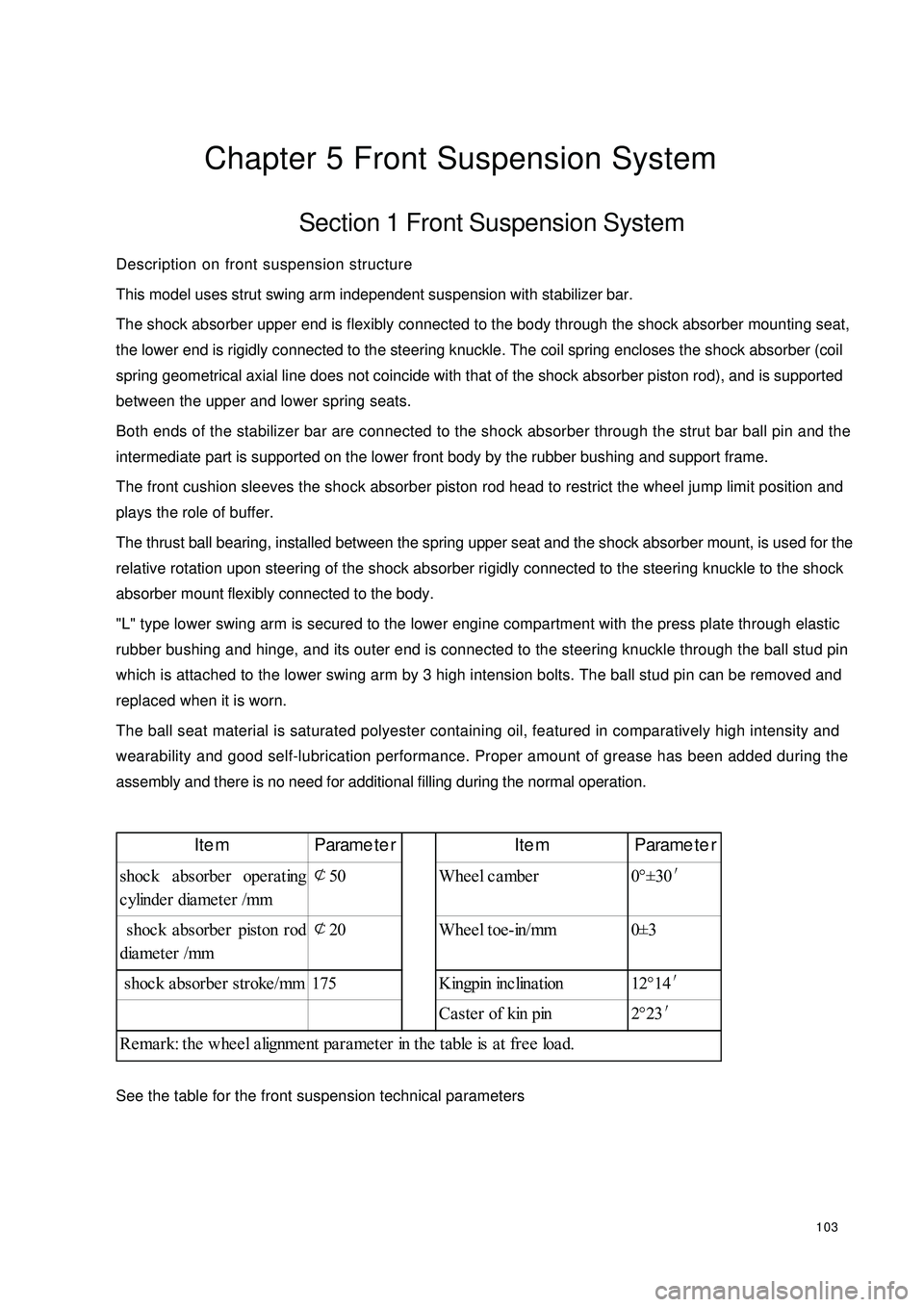
103Chapter 5 Front Suspension SystemSection 1 Front Suspension SystemDescription on front suspension structure
This model uses strut swing arm independent suspension with stabilizer bar.
The shock absorber upper end is flexibly connected to the body through the shock absorber mounting seat,
the lower end is rigidly connected to the steering knuckle. The coil spring encloses the shock absorber (coil
spring geometrical axial line does not coincide with that of the shock absorber piston rod), and is supported
between the upper and lower spring seats.
Both ends of the stabilizer bar are connected to the shock absorber through the strut bar ball pin and the
intermediate part is supported on the lower front body by the rubber bushing and support frame.
The front cushion sleeves the shock absorber piston rod head to restrict the wheel jump limit position and
plays the role of buffer.
The thrust ball bearing, installed between the spring upper seat and the shock absorber mount, is used for the
relative rotation upon steering of the shock absorber rigidly connected to the steering knuckle to the shock
absorber mount flexibly connected to the body.
"L" type lower swing arm is secured to the lower engine compartment with the press plate through elastic
rubber bushing and hinge, and its outer end is connected to the steering knuckle through the ball stud pin
which is attached to the lower swing arm by 3 high intension bolts. The ball stud pin can be removed and
replaced when it is worn.
The ball seat material is saturated polyester containing oil, featured in comparatively high intensity and
wearability and good self-lubrication performance. Proper amount of grease has been added during the
assembly and there is no need for additional filling during the normal operation.
See the table for the front suspension technical parametersItem Parameter Item Parameter
shoc k a bsorbe r ope ra ting
cylinder diameter /mm¢
50 Wheel camber 0°±30′
shoc k a bsorbe r piston rod
diameter /mm¢
20 Wheel toe-in/mm 0±3
shoc k a bsorbe r stroke /mm 175 Kingpin inc lina tion 12°14′
Ca ste r of kin pin 2°23′
Remark: the wheel alignment parameter in the table is at free load.
Page 114 of 392
107Section 4 Front Strut AssemblyComponents:WasherMount CoverShock Absorber Mount SupportBig WasherThrust Ball BearingSpring Upper SeatFront Coil Spring
Upper InsulatorFront Coil SpringLeft Brake Assembly ABS Sensor Wire HarnessFront Brake Hose Stabilizer Bar Left
Link Rod AssemblyLF Shock Absorber AssemblyFront Coil Spring Lower InsulatorFront BumperFront Shock Absorber
Protecting Sleeve
Page 115 of 392
108Replacement1. Remove the front wheel.
2. Remove the ABS sensor from the steering knuckle. Separate the sensor and signal wire from the wire
harness bracket on the front shock absorber.
3. Separate the front brake hose
Remove 2 clips and separate the front brake hose from the front shock absorber bracket.
4. Remove the stabilizer bar link rod assembly
Remove the nut connecting the stabilizer bar link rod assembly and the shock absorber.
5. Remove the front shock absorber with the coil spring
(1) Remove the nuts and bolts connecting the shock absorber and brake.
(2) Remove the 4 nuts connecting the front shock absorber and vehicle body.
Notice: reliable object shall be used to support the brake assembly!
Page 116 of 392
1096. Disassemble the front strut assembly
(1) Remove the nut on the shock absorber.
Notice: the elasticity of the spring is recovered!
(2) Remove the washer, collar, shock absorber mount seat and big washer.
(3) Remove spring upper seat, front coil spring , front shock absorber boot, front dumper, front coil spring
lower insulator.
7. Assemble the front strut assembly
The assembly of the front strut assembly is in the reverse order of disassembly.
Notice:
(1) Use special fixture when installing the nut on the shock absorber piston rod, be
careful not to let the spring rebound. Torque: 80~90 N.Sm.(2) Install the 4 bolts attaching the front strut assembly to the body. Torque: 25~30N.m.(3) Install the 2 bolts and nuts of the front strut assembly and the brake.
Torque: 90~100N.m.
(4) Install the attaching nuts on the stabilizer bar link rod assembly and shock absorber.
Torque: 50~60N.m.
(5) Install the ABS sensor and secure the signal wire.
Page 123 of 392

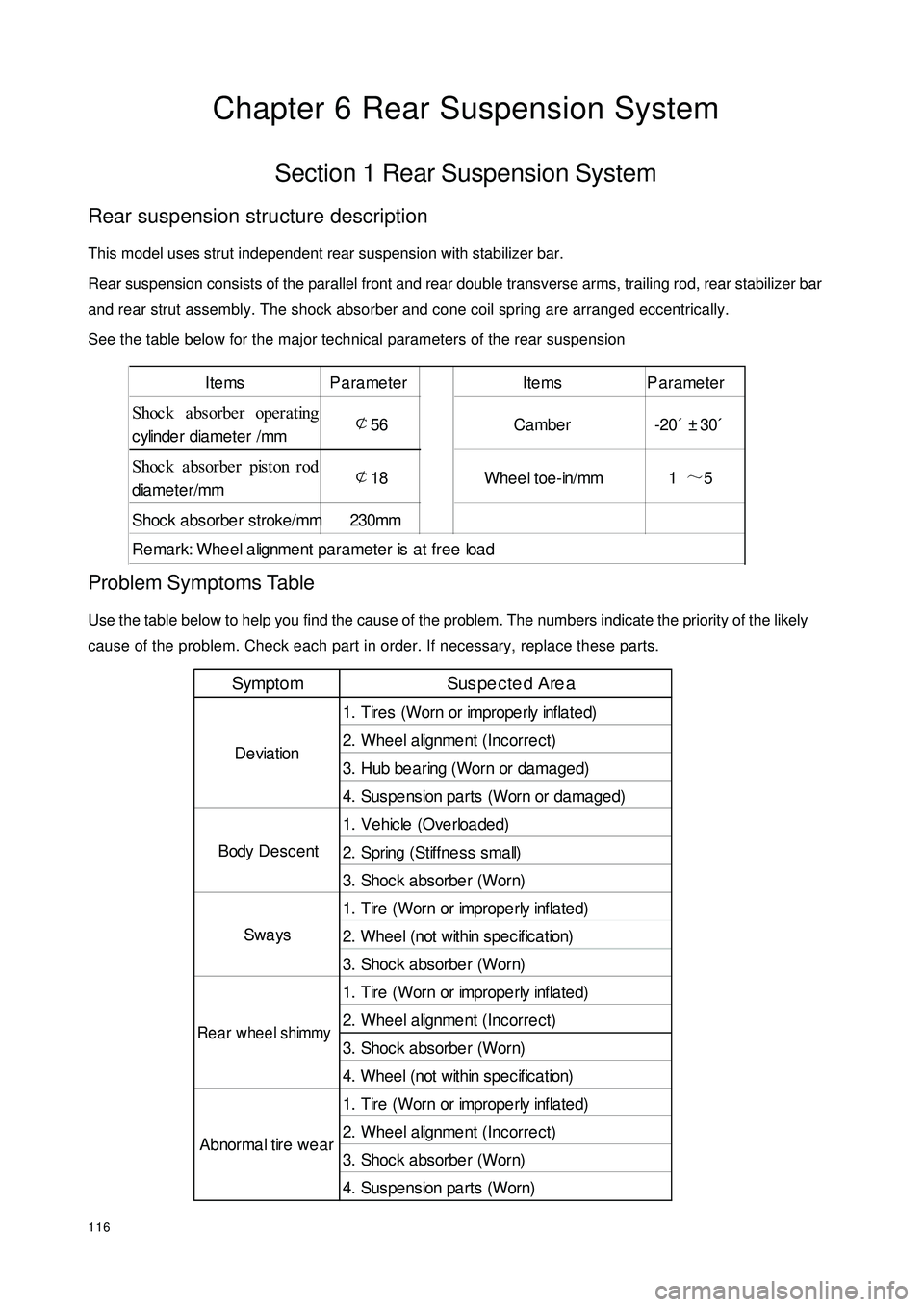
116Chapter 6 Rear Suspension SystemSection 1 Rear Suspension SystemRear suspension structure descriptionThis model uses strut independent rear suspension with stabilizer bar.
Rear suspension consists of the parallel front and rear double transverse arms, trailing rod, rear stabilizer bar
and rear strut assembly. The shock absorber and cone coil spring are arranged eccentrically.
See the table below for the major technical parameters of the rear suspensionProblem Symptoms TableUse the table below to help you find the cause of the problem. The numbers indicate the priority of the likely
cause of the problem. Check each part in order. If necessary, replace these parts.Items Parameter Items Parameter
Shoc k a bsorbe r operating
cylinder diameter /mm¢
56 Cambe r -20´±30´
Shoc k a bsorbe r piston rod
diameter/mm¢
18 Wheel toe-in/mm 1~
5
Shoc k absorbe r stroke/mm 230mm
Remark: Wheel alignment parameter is at free loadSympto m Sus pe cte d Are a
1. Tires (Worn or imprope rly infla te d)
2. Wheel alignment (Incorrect)
3. Hub be a ring (Worn or da ma ge d)
4. Suspe nsion pa rts (Worn or da ma ge d)
1. Ve hic le (Ove rloa de d)
2. Spring (Stiffness small)
3. Shoc k a bsorbe r (Worn)
1. Tire (Worn or imprope rly inflate d)
2. W he e l ( not w it hin s pe c if ic a t ion)
3. Shoc k a bsorbe r (Worn)
1. Tire (Worn or imprope rly inflate d)
2. Wheel alignment (Incorrect)
3. Shoc k a bsorbe r (Worn)
4. W he e l ( not w it hin s pe c if ic a t ion)
1. Tire (Worn or imprope rly inflate d)
2. Wheel alignment (Incorrect)
3. Shoc k a bsorbe r (Worn)
4. Sus pe nsion pa rts (Worn) Abnormal tire wearDeviation
Body Desc ent
SwaysRear wheel shimmy
Page 136 of 392

129Symptom TableThe table below is helpful to find the cause of the problem. The numbers indicate the priority of the likely
cause of the problem. Check each part in order. Repair or replace these parts or assemblies if necessary.On-vehicle inspection1. Check steering wheel free stroke
(1) Stop vehicle and keep the tires straight ahead.
(2) Rotate the steering wheel lightly, check the steering wheel free stroke.
Maximum free stroke: 30mmSymptom Like ly Ca us e
1.
Tire (imprope rly infla te d)
2.
P owe r ste ering fluid (insuffic ie nt)
3.
Front whe e l a lignme nt (inc orre c t)
4.
Ste e ring knuckle (worn)
5.
Swing a rm ba ll stud pin joint (worn)
6.
St e e r ing c olumn ( be nt or binding)
7.
P owe r ste ering pump a ssembly (Worn)
8.
Power steering gear assembly (Fault)
1.
Tire (imprope rly infla te d)
2.
Front whe e l a lignme nt (inc orre c t)
3.
St e e r ing c olumn ( be nt or binding)
4.
Power steering gear assembly (Oil pressure too low)
1.
Ste e ring knuckle (worn)
2.
Swing a rm ba ll stud pin joint (worn)
3.
Inte rmediate sha ft, sliding yoke (worn)
4.
Front whe e l be a ring (w orn)
5.
P owe r ste ering ge a r asse mbly (worn)
1.
P owe r ste ering pump fluid leve l (low)
2.
St e e r ing s ys t e m ba ll joint ( w or n)
3.
Power steering pump assembly (damaged)
4.
Power steering gear assembly (damaged) He avy ste eringPoor returnExcessive
clearance and
play
A bnor ma l nois eMaximum Free Stroke
Page 142 of 392

135Replacement1. Drain the power steering system fluid
2. Remove the power steering high and low pressure pipe
3. Loosen the union screw of the high and low pressure pipe on the steering gear assembly, loosen the pipe
clip.
4. Loosen the drive belt
5. Remove the power steering pump with bracket assembly from the engine
Remove the 4 attaching bolts between the steering pump belt bracket and the engine6.Install the power steering pump bracket assemblySecure the power steering pump bracket assembly to the engine,
The torque of the M10 bolt is 45~79N.m, the torque of the M8 bolt is 16~26N.m7. Install the drive belt, make sure the installation position is correct
8. Install the power steering high and low pressure pipe(1)Connect the union thread of the high and low pressure pipe to the steering gear,
torque: 19~33N.m
(2) Use the retaining clip to secure the low pressure pipe to the cowl baffle panel of the body
(3)Connect the union thread of the high pressure pipe to the power steering pump,
torque: 19~33N.m
(4) Connect the union thread of the low pressure pipe to the reservoir, torque: 19~33N.m
9. Bleed the power steering pipeline system, check the pipeline system for leakage
10. Check the oil reservoir inner fluid level