2008 GEELY CK lock
[x] Cancel search: lockPage 73 of 392

66f. The idle control valve is faulty;
g. The water temperature sensor is damaged;
h. The vacuum pressure sensor is damaged;
i. The air filter is blocked;
j. The injector leaks;
k. The compression pressure in the cylinder is too low;
l. The intake temperature sensor is damaged.
(3) Diagnosis and Troubleshooting
a. Check high pressure spark, check whether the high pressure spark on the ignition coil high pressure
bus and extension are OK, if the bus spark is week, replace the ignition coil, if the bus spark is OK
while the extension spark is too week, replace the ignition coil also; In addition, excessive spark
plug clearance will influence the starting feature, the clearance of the spark plug shall be adjusted
to normal value (0.8±0.1mm);
b. If there is low fuel pressure, check whether the battery voltage is OK, otherwise it shall be
troubleshot or replaced; check fuel pump check valve for leakage, check fuel filter and fuel pipe for
block, if there are leakage or block, replace or troubleshoot them;
c. If there is leakage for fuel pressure regulator, intake manifold is likely to be mixed with gasoline and
it is hard to start, troubleshoot or replace them;
d. Idle control valve can not be opened to maximum position due to mechanical wear, aging or control
circuit failure, the idle control valve shall be replaced and the control circuit failure shall be troubleshot;
e. If the water temperature sensor data is not accurate, it may cause small injection, check the water
temperature sensor based on the standard data and calibrate the data;
f. There is big time lag for intake pressure temperature sensor that makes it somewhat insensitive at
low speed and result in inaccurate injection, adjustment or replacement shall be made;
g. If the air cleaner filter is too dirty, the air flow resistance is excessively big, resulting in hard start,
as a result of it, the filter shall be replaced.
In a word, there are many factors causing the starting failure of the engine, analysis shall be made based on
the severe conditions of the faults. Generally speaking, check the ignition system first, then check intake
system, fuel system, control system, at last check the cylinder pressure, check the DTC before checking the
trouble. The diagnosis and troubleshooting procedures for starting failure of the engine are shown in (Figure
148).
Page 79 of 392

724. Big fuel consumption
(1) Symptom:
Engine power is ok, but the fuel consumption is big, exhaust pipe discharges black smoke.
(2) Causes and Troubleshooting:
a. When idling, idle speed is high and shall be adjusted;
b. Water temperature sensor fault, service or replace it;
c. Water temperature switch and thermostat fault, repair or replace it;
d. Oxygen sensor fault, repair or replace it;
e. Fuel pressure is big and shall be adjusted;
f. Injector fault (fuel leakage), repair or replace it;
g. Throttle position sensor fault, repair or replace it;
h. Fuel pressure regulator is damaged and shall be replaced;
i. Intake pressure temperature sensor fault, repair or replace it.
5. Unstable idle, liable to be turned off
(1) Symptom:
Engine starts normally, but the idle is unstable regardless of cold or hot status, idle speed is too low and
the engine is liable to be turned off.
(2) Causes and Troubleshooting
a. Poor idle control valve operation, repair or replace it;
b. Low idle speed and faulty or improperly adjusted idle control valve, troubleshoot it;
c. Water temperature sensor fault, repair or replace it;
d. Poor intake system seal, need to be repaired;
e. High voltage spark is too weak, spark plug carbon deposit or electrode clearance is too small, need
to be repaired, cleared and adjusted;
f. Pressure sensor fault, repair or replace it;
g. The compression pressure in the cylinder is too low, need to be serviced;
h. Fuel line pressure is too low, needed to be serviced;
i. Air cleaner is clogged, clean or replace it;
j. Poor injector atomization, fuel leakage, block or big injection variation, need to be repaired;
(3) Diagnosis procedure (Figure 152)
6. Unstable idle at cold status, liable to be turned off
(1) Symptom
During the cold start, idle is unstable and engine is liable to be turned off, the normal idle is recovered
after warming of the engine.
(2) Causes and Troubleshooting
a. Water temperature sensor fault, repair or replace it;
b. idle control valve fault, repair or replace it.
Page 82 of 392

7510. Engine overheat (Table 6)
Table 6Ite m Symptom Trouble shootingRepair or replace
Bad radiator hose Replace
Bad radiator tube strapSupplement welding, otherwise
replace it
Bad cylinder gasket Replace
Cracky cylinder blockRemedy with infiltration technology
or replace it
Poor water pump seal Replace the seal
Replace the anti-freeze liquid
Replace the thermostatBroken we ldSupplement weldingCorrosion result in pin holeFill the pinhole with clear coat,
otherwise replace it
Repair and dredge
Improve the ventilation
Repair or replace the water pump
Troubleshooting, replace the motor if
it is d a ma ge d
Replace
Repair and dredge
Repair or replace the oil pan if there
is o il le a k a ge , r e fill t he o il if it is no t
s up p le me nt e d in t imeCause
Ba d ra diator c over
Clogge d cooling tubePoor ventilationWater
le a ka ge
Anti-fre eze liquid not repla ce d
Bad thermostat
Radiator is
faultyWater
le a ka ge Insufficient
coolantF a ulty fa n vo lta ge
Disabled radiator temperature control
switch
Water jacket is clogged because of too much scale
I ns uffic ie nt e ngine o il ( o il le a k a ge o r d e la ye d filling)P oor
c ooling
Poor FanFaulty water pump
Page 90 of 392

83ECU microcomputer consists of microprocessor, memory, clock generator, timer, I/O interface and input
level A/D converter that are integrated in a large scale integrated circuit chip, that is SCM (Single Chip
Microcomputer).
1. Input level
The input signals from the sensor are pre-processed by the input level. The input signals are sent to protected
circuit first, sometimes through the signal converter and amplifier, and then sent to microcomputer.
The sensor signal is separated into switch type and analog type. Ignition on/off signal, camshaft position
signal, vehicle speed signal and A/C signal are switch type; Signals such as battery voltage, engine temperature,
intake temperature, airflow, intake manifold absolute pressure, throttle opening, excessive air coefficient,
knock, A/C refrigerant pressure are analog type. Analogy signal can only be processed by the digital micro-
computer after being converted into digital signal by A/D converter. Hence, data collection shall be made
first for analog signal, and the sampling shall be maintained also.
Speed and crankshaft position reference signal from the sensor is processed in a dedicated circuit to restrain
the interference pulse.
2. Microcomputer
The microcomputer of the engine electronic control unit is integrated in a single chip microcomputer, consist-
ing of the following:
(1) Microprocessor, microprocessor is also called as central processing unit (CPU), consisting of the following
three parts:
Arithmetic logic unit.
Register group.
Controller.
(2) System assembly, The data transferred among the internal sections of the single chip microcomputer
(SCM) is performed on the internal bus, while that between the SCM and other components is performed
on the external bus. The external bus is also called system bus. It is separated into data bus, address bus
and control bus.
(3) Memory, the memory is designed to store the binary data. The primary components of the memory are:
Memory.
Data register.
Address register, address decoder.
a. Memory controller
(4) A/D converter
(5) I/O interface.
(6) Clock generator.
(7) Timer
(8) CAPCOM unit.
(9) Watchdog timer.
(10) Interrupt system.
Page 93 of 392

86Replacement1. Remove shift lever assembly
(1) Pull upwards to separate the shift lever assembly leather boot from the auxiliary console
(2) Loosen the shift lever set screw with inner hex wrench. Remove the shift lever assembly counterclockwise
2. Remove auxiliary console
3. Remove control lever dust cover
Remove the 4 nuts on the control lever dust cover and the body.
4. Remove dust cover retainer
5. Remove control pull rod assembly
(1) Remove the pull rod connecting bolt (Place 2)
(2) Remove 2 hex flange bolts (Place 1)
(3) Remove the 2 flange nuts attaching the control pull rod to the body in the trench
6. The installation is in the reverse order of the above operation.
Notice:
(1) Pull rod (to transmission) attach bolt torque: 40~50N.m
(2) The torque of the two nuts attaching the control mechanism to the body: 20~25N.mBottom Panel
Assembly of
BodyControl Pull Rod Assembly
Transmission Assembly
Page 95 of 392

88Replacement1. Remove shift lever assembly
(1) Pull upwards to separate shift lever assembly leather boot from the auxiliary console
(2) Loosen shift lever set screw with inner hex wrench. Remove the shift lever assembly counterclockwise.
2. Remove the auxiliary console
3. Remove the 4 nuts connecting manual shift assembly and the floor
4. Remove the shift cushion
5. Remove transmission control device assembly
(1) Remove the set nut on the cable seal press plate
(2) Remove the cotter pin and the flat washer connecting the cable and the rocker arm on the transmission
(3) Remove the E-shaped clip plate on the cable bracket retaining the cableShift Control
CablesE Shaped
Clip PlateBall SeatShift Lever Assembly LeverBall PinSpindle IISpindle IE Shaped
Clip PlateWave WasherBushBushSpring BushBall Pin Seat Torsion Spring Support
Plate Bottom BracketConjuction
Frame
Page 96 of 392

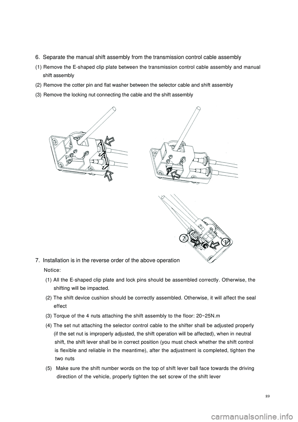
896. Separate the manual shift assembly from the transmission control cable assembly
(1) Remove the E-shaped clip plate between the transmission control cable assembly and manual
shift assembly
(2) Remove the cotter pin and flat washer between the selector cable and shift assembly
(3) Remove the locking nut connecting the cable and the shift assembly
7. Installation is in the reverse order of the above operation
Notice:
(1) All the E-shaped clip plate and lock pins should be assembled correctly. Otherwise, the
shifting will be impacted.
(2) The shift device cushion should be correctly assembled. Otherwise, it will affect the seal
effect
(3) Torque of the 4 nuts attaching the shift assembly to the floor: 20~25N.m
(4) The set nut attaching the selector control cable to the shifter shall be adjusted properly
(if the set nut is improperly adjusted, the shift operation will be affected), when in neutral
shift, the shift lever shall be in correct position (you must check whether the shift control
is flexible and reliable in the meantime), after the adjustment is completed, tighten the
two nuts
(5) Make sure the shift number words on the top of shift lever ball face towards the driving
direction of the vehicle, properly tighten the set screw of the shift lever
Page 99 of 392

92Adjustment1. Check and adjust clutch pedal height
The clutch pedal height should be 180~186 mm. Adjust the pedal by adjusting bolts.
2. Check and adjust clutch pedal stroke and free stroke
(1) The clutch pedal stroke: 134~142mm
(2) The clutch pedal free stroke: 10~30 mm
If the clutch pedal stroke and free stroke are not within specification, adjust it by adjusting the location of
the adjusting nut on the clutch cable. Re-adjust the clutch pedal height if necessary.
3. Check that the clutch pedal operates in flexible and reliable way
Notice:
(1) Make sure the clutch is fully applied and completely released when control the clutch
pedal.
(2) The clutch pedal must have certain free stroke. Otherwise, the full application of the
clutch may be impacted
(3) Tighten the lock nut after adjustmentConnect The
Clutch CableBushingBushingAdjusting BoltBrake Pedal Assembly Sleeve Clutch Pedal Torsion Spring Retainer Pedal MatClutch Pedal AssemblyClutch
Pedal
Bracket
AssemblyAdjusting Nut