Page 203 of 392

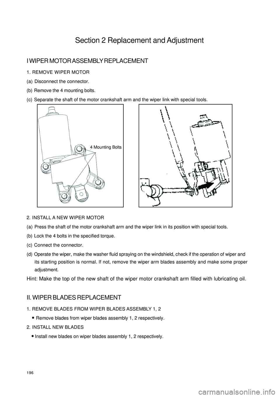
196Section 2 Replacement and AdjustmentI WIPER MOTOR ASSEMBLY REPLACEMENT1. REMOVE WIPER MOTOR
(a) Disconnect the connector.
(b) Remove the 4 mounting bolts.
(c) Separate the shaft of the motor crankshaft arm and the wiper link with special tools.
2. INSTALL A NEW WIPER MOTOR
(a) Press the shaft of the motor crankshaft arm and the wiper link in its position with special tools.
(b) Lock the 4 bolts in the specified torque.
(c) Connect the connector.
(d) Operate the wiper, make the washer fluid spraying on the windshield, check if the operation of wiper and
its starting position is normal. If not, remove the wiper arm blades assembly and make some proper
adjustment.
Hint: Make the top of the new shaft of the wiper motor crankshaft arm filled with lubricating oil.II. WIPER BLADES REPLACEMENT1. REMOVE BLADES FROM WIPER BLADES ASSEMBLY 1, 2
�yRemove blades from wiper blades assembly 1, 2 respectively.
2. INSTALL NEW BLADES
�yInstall new blades on wiper blades assembly 1, 2 respectively.4 Mounting Bolts
Page 204 of 392
197III. WIPER SWITCH ASSEMBLY REPLACEMENT1. DETACH STEERING WHEEL ASSEMBLY
(a) Disconnect the main power source of the vehicle.
(b) Remove the passenger SRS module assembly, and cautiously put it in a safe place.
(c) Loosen steering wheel lock-bolts and remove the assembly.
2. REMOVE WIPER SWITCH
(a) Disconnect the connector.
(b) Remove the 2 tapping screws that are for mounting the wiper switch, take out the wiper switch from the
bracket of the combination switch.IV. WASHER NOZZLEADJUSTMENT
1. INSPECT WASHER NOZZLE
(a) Start the engine, check if the position where the washer fluid from the nozzle sprays the windshield is in
the central or upper of the area wiped by the blades.
(b) Change the direction (horizontal) of the nozzle hole to adjust the point where washer fluid sprays the
windshield.
Page 216 of 392

2095. DOOE COURTESY LAMP SWITCH ( ON DOOR LOCK ACTUATOR)
Inspect door courtesy lamp switch for continuity.
Inspect continuity between the terminal and the ground when the switch operates.
If it is not as specified, replace the switch.
6. REAR TRUNK LAMP SWITCH ASSEMBLY
Inspect rear trunk lamp switch for continuity.
Inspect continuity between the terminal and the ground when the switch operates.
If it is not as specified, replace the switch.
7. ROOM LAMP ASSEMBLY
Inspect each terminal on room lamp assembly for continuity.
If it is not as specified, replace the dome lamp or the switch.S w it c h pos it ion T e s t e d t e r mina l C ondit ion
ON 1 – Ground the body Continuity
OFF 1 – Ground the body No c ontinuityTe ste d te rmina l Condition
ON 1-2 Continuity
OFF 1-2 2-3 No continuity
DOOR (The door is a jar) 2-3 Continuity
DOOR (The door is c lose d) 2-3 No continuity
ON (Switc h is pre ssed) 1-2 Continuity
OFF 1-2 No continuity Switc h position
Interior dome la mp
LR and RR reading lampsSwitch position Tested terminal Condition
ON (The door is we ll close d) 1 – Ground the body Continuity
OFF (The door is aja r) 1 – Ground the body No c ontinuity1
2
3
Page 219 of 392
212II.INSTALLATION1. Install the electrical connector of the headlamp assembly.
2. Install the headlamp assembly and the 3 mounting bolts.
3. Install the front bumper.
4. Adjust the condition of the vehicle.
5. Adjust the headlamp beam.III.HEADLAMP BULB REPLACEMENT1 - LOW BEAM DUST COVER 2 - HIGH BEAM DUST COVER 3 - TURN SIGNAL LAMP DUST
COVER 4 - HEADLAMP HOLDER
1. Replace the high and low beam bulbs
�y Turn and remove the dust cover counter-clockwise
�y Pull out the bulb plug
�y Press and release the wire clip
�y Pull out the lamp-holder, and remove the bulb
�y Replace the bulb
2. Replace the turn signal lamp bulbs
�y Remove the 3 screws on the dust cover with screwdriver
�yTurn the lamp-holder counter-clockwise. Pull out the lamp-holder, and remove the bulb
�yReplace the bulb
3. Replace the headlamp bulbs
�yTurn the lamp-holder counter-clockwise. Pull out the lamp-holder, remove the bulb, and replace the
bulb.1 2 3 4
Page 222 of 392
215Section 4 Front Fog Lamp ReplacementI. REMOVAL1. Remove the front bumper.(See bumper replacement)
2. Remove the electrical connector.
3. Remove the mounting bolts (A, B as shown in the illustration).
4. Remove the front fog lamp assembly.II. INSTALLATION1. Install the front fog lamp assembly.
2. Install the mounting bolts.
3. Install the electrical connector.
4. Install the front bumper.
5. Adjust the condition of the vehicle.
6. Adjust the front fog lamp beam.III. FRONT FOG LAMP BULB REPLACEMENT1. Press and Turn counter-clockwise, then remove the dust cover
2. Pull out the bulb
3. Replace the bulbABElectrical
Connection
Page 223 of 392
216IV. FRONT FOG LAMP BEAM ADJUSTMENT1. Adjust the tire inflation pressure with the standard value
2. Start the engine
3. Turn the fog lamp switch ON
4. Adjust the fog lamp beam.
Turn the bolt A for adjusting fog lamp beam in vertical direction.
NOTES:
Turn the screwdriver counter-clockwise to make the light beam up, clockwise make the light beam down.
Page 225 of 392
218II. INSTALLATION1. Install the rear combination lamp and then the 3 mounting bolts.
2. Install the electrical connector.
3. Install the rear trunk interior trim.
4. Install the seal strip.III. REAR COMBINATION LAMP BULB REPLACEMENT1. Remove the O-ring seal.
2. Turn the lamp-holder counter-clockwise. Pull out the lamp-holder.
3. Remove the bulb and replace the bulb.Section 6 High Mounted Stop Lamp Replacement�zRemove the High mounted stop lamp in direction 1 and 2. (as shown above in the illustration)
�zDisconnect the connector.Partition
High Mounted
Stop Lamp
Page 249 of 392

242Chapter 7
SRS (Supplemental Restraint System)Section 1 SRS-General InformationI. PRECAUTIONFor safe reasons, read the following precautions before starting any operation.
1. When servicing the SRS, correct sequence and items are described in the following chapter.
2. Instruments and special tools recommended in this chapter shall be used for operation.
3. When servicing the following components, replace them with the new ones if there is a failure.
(1) SRS ECU
(2) Clock Spring Module
(3) Driver Airbag Module
(4) Passenger Airbag Assembly (Option)
4. If there is any abnormality in the wire harness of the SRS, replace it with a new one. Correct or replace the
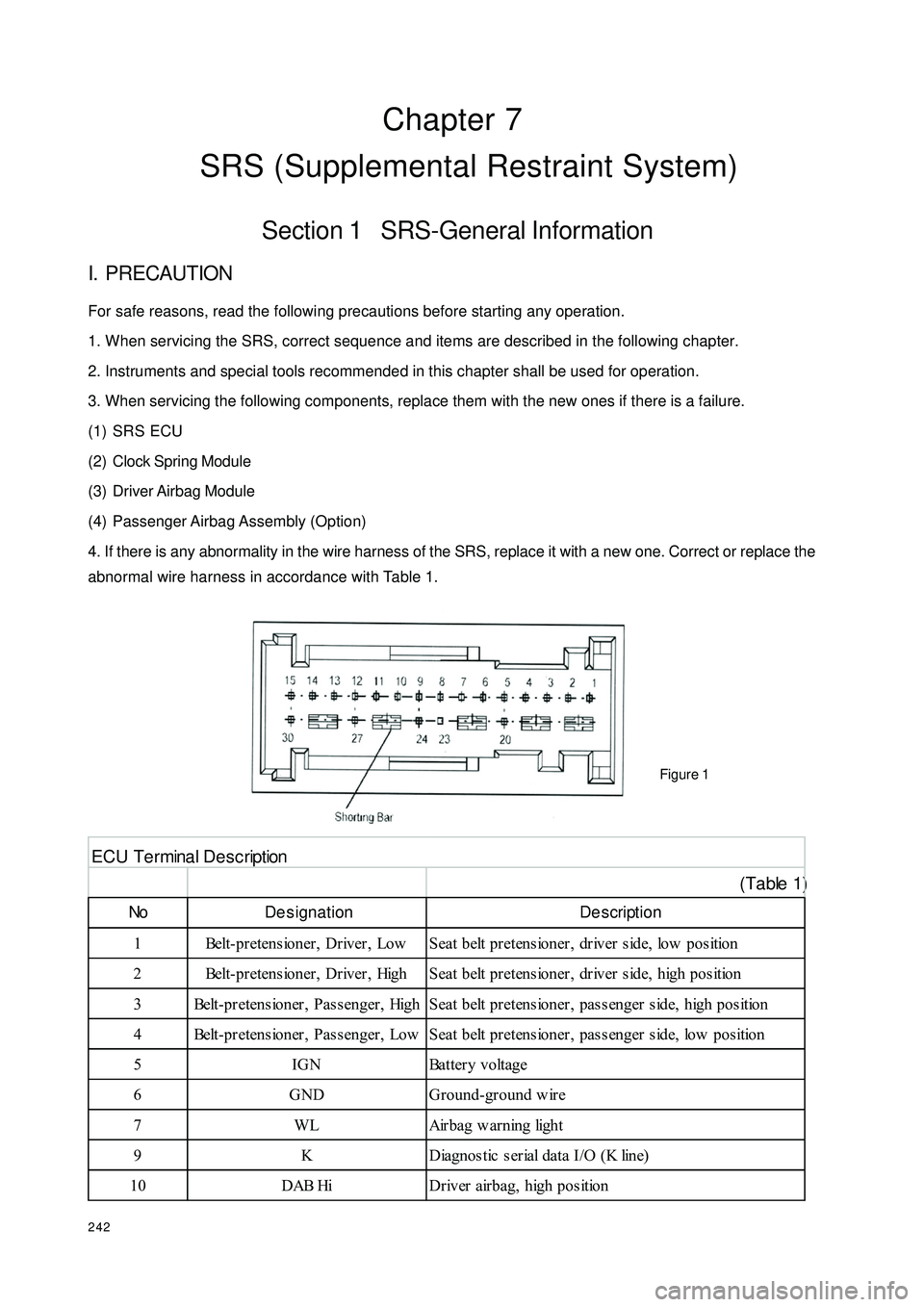
abnormal wire harness in accordance with Table 1.
Figure 1 (Table 1)No De signation De scription
1 Belt-pretensioner, Driver, Low Seat belt pretensioner, driver side, low position
2 Belt-pretensioner, Driver, High Seat belt pretensioner, driver side, high position
3 Belt-pretensioner, Passenger, High Seat belt pretensioner, passenger side, high position
4 Belt-pretensioner, Passenger, Low Seat belt pretensioner, passenger side, low position
5 IGN Battery voltage
6 GND Ground-ground w ire
7 WL Airbag w arning light
9 K Diagnostic serial data I/O (K line)
10 DAB Hi Driver airbag, high positionE C U T e r mina l D e s c r ipt ion