Page 107 of 392
100(3) Check the Rzeppa Constant velocity universal joint for looseness
(4) Check the boot for damage
Notice: Check that the propeller shaft assembly is placed horizontal.
8. Disassemble the tripod constant velocity universal joint boot Use screwdriver to loose the tripod constant
velocity universal joint boot band, remove the boot
Notice: Replace the band if it is distorted
9. Disassembly the tripod constant velocity universal joint
(1) Remove the old grease
(2) Use the mark pen to place a matchmark on the inboard and outboard joint
Notice: Do not punch the marks
(3) Remove the outboard knuckle
(4) Use snap ring pliers to remove the snap ring
(5) Use mark pen to place matchmarks on the tripod ball joint and outboard joint
(6) Use brass bar and hammer to remove the tripod ball joint
Notice: Do not tap the rollerMarkBrass BarMark
Page 108 of 392

10110. Remove the snap ring on the spline shaft end of the tripod constant velocity joint
Notice: Do not damage the snap ring, or it shall be replaced
11.Disassemble the Rzeppa Constant velocity universal joint boot Use screwdriver to loosen the
Rzeppa Constant velocity universal joint boot band, remove the boot
Notice: Replace the band if it is distorted
12. Disassemble the Rzeppa Constant velocity universal joint
(1) Remove the old grease
(2) Use the mark pen to make a matchmark on the inboard and outboard joint
Notice: Do not punch the marks
13. Installation is in the reverse order of removal procedure
Notice:
(1) Apply proper amount of long life grease as specified when assembling the tripod
velocity universal joint and Rzeppa Constant velocity universal joint, and then
assemble it according to the matchmark.(2) Keep both sides of the spline shaft clean, the boot intact and the band assembled into place(3) The tripod constant velocity joint spline shaft and the differential shall be assembled into place, with the snap ring opening facing down, use rubber hammer to tap it
appropriately when necessary
(4) Propeller shaft attaching nut torque: 145~155N.m, install the cotter pin
(5) Steering knuckle lower swing arm assembly ball stud pin retaining bolt and nut
torque: 80~90N.m
(6) Tie rod ball stud pin attaching nut torque:27~39N.m, install the cotter pin
Page 116 of 392
1096. Disassemble the front strut assembly
(1) Remove the nut on the shock absorber.
Notice: the elasticity of the spring is recovered!
(2) Remove the washer, collar, shock absorber mount seat and big washer.
(3) Remove spring upper seat, front coil spring , front shock absorber boot, front dumper, front coil spring
lower insulator.
7. Assemble the front strut assembly
The assembly of the front strut assembly is in the reverse order of disassembly.
Notice:
(1) Use special fixture when installing the nut on the shock absorber piston rod, be
careful not to let the spring rebound. Torque: 80~90 N.Sm.(2) Install the 4 bolts attaching the front strut assembly to the body. Torque: 25~30N.m.(3) Install the 2 bolts and nuts of the front strut assembly and the brake.
Torque: 90~100N.m.
(4) Install the attaching nuts on the stabilizer bar link rod assembly and shock absorber.
Torque: 50~60N.m.
(5) Install the ABS sensor and secure the signal wire.
Page 144 of 392
137Tie Rod RH Ball Stud PinLock NutWire ClipNo.1 BootBandPipeO-ringO-ringO-ringBand
Wire ClipNo. 2 BootLock NutTie Rod LH Ball Stud PinJoint Sub-assemblyJoint Sub-assemblyReplacement1. Drain the power steering system fluid
2. Separate the tie rod from the steering knuckle
(1) Remove the cotter pin, loosen the groove type lock nut
(2) Separate the tie rod ball stud joint from the steering knuckle taper hole
Page 145 of 392

1383. Loosen the union thread of the high and low pressure pipes on the steering gear assembly
4. Remove the boot band and No. 1, No. 2 boots
5. Disconnect the power steering gear assembly from the steering column
Remove the steering gear pinion shaft spline lock bolt on the universal joint yoke
6. Remove power steering gear assembly
Remove 4 steering gear assembly set bolts, remove the power steering gear assembly
7. Installation is in the reverse order of the removal
Notice:
(1) Insert the steering gear pinion shaft spline into the spline hole of the universal joint
yoke, make sure that the positions of the notch of the steering gear pinion shaft and the
lock bolt of the universal joint yoke are correct
(2) Secure the power steering gear with 4 bolts, torque: 63~93N.m
(3) Tighten the steering gear pinion shaft spline lock bolt on the universal joint yoke, torque:
22~34N.m
(4) Tighten the 4 set bolts of the boot band and boot torque: 16~26N.m
(5) Install the union thread of the power steering high and low pressure pipe to the power
steering gear, torque: 19~33N.m
(6) Connect the tie rod ball stud pin with the steering knuckle, make sure that the mating
surface of the tie rod ball stud pin and the steering knuckle is clean, tighten the slot nut,
torque: 27~39N.m. Install the cotter pin, make sure of the correct installation
(7) Add appropriate amount of specified power steering fluid, bleed the power steering sys-
tem
(8) Check the power steering pipeline system for leakage
(9) Check the front wheel alignment and front wheel left and right limit turn angle, adjust the
toe in if necessary and tighten the tie rod lock nut
(10)Check the position of the steering wheel. It is required that the steering wheel spokes
are basically symmetrical when the vehicle is driven straight ahead, reassemble the steering
wheel if necessary
Page 151 of 392
144Section 5 Front Brake AssemblyComponents
Repairing1. Remove the front wheel
2. Drain the brake fluid. Remove the brake hose
3. Remove the front brake caliper
(1) Remove the brake hose union thread from the front brake cylinder. Disconnect the hose
(2) Remove 2 installing bolts
4. Remove the front brake pad
5. Remove the front left disc caliper
6. Remove the sliding pin bootDisk Brake Wheel
Cylinder BracketSliding Pin BootInner Floating Clip PlateScrew PlugBrake Caliper
HousingInner
DamperInner Pad
Backing
PlateInner PadOuter PadOuter Pad
Backing PlateOuter
DamperOuter Floating
Clip PlateAlarm
PlateWheel
Cylinder
PistonWheel
Cylinder
Piston SealWheel
Cylinder
BootSteel Wire
Snap RingShort Pin
Set BoltShort BushingGuide Boot (II)Splash ShieldFront Ring GearRetaining
RingWheel Hub BoltFront Wheel
Hub Bearing
Wheel HubDisc
Page 152 of 392

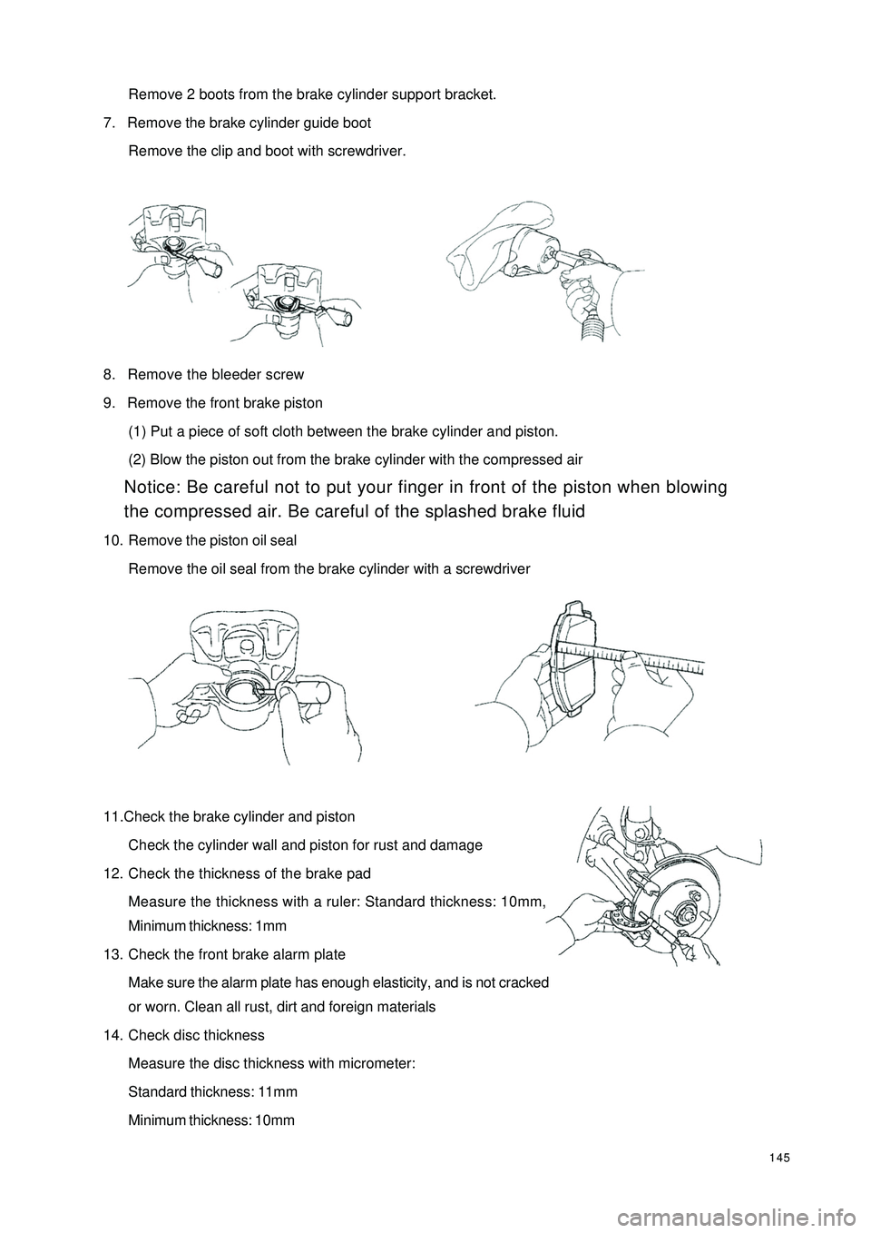
145Remove 2 boots from the brake cylinder support bracket.
7. Remove the brake cylinder guide boot
Remove the clip and boot with screwdriver.
8. Remove the bleeder screw
9. Remove the front brake piston
(1) Put a piece of soft cloth between the brake cylinder and piston.
(2) Blow the piston out from the brake cylinder with the compressed air
Notice: Be careful not to put your finger in front of the piston when blowing
the compressed air. Be careful of the splashed brake fluid
10. Remove the piston oil seal
Remove the oil seal from the brake cylinder with a screwdriver
11.Check the brake cylinder and piston
Check the cylinder wall and piston for rust and damage
12. Check the thickness of the brake pad
Measure the thickness with a ruler: Standard thickness: 10mm,
Minimum thickness: 1mm
13. Check the front brake alarm plate
Make sure the alarm plate has enough elasticity, and is not cracked
or worn. Clean all rust, dirt and foreign materials
14. Check disc thickness
Measure the disc thickness with micrometer:
Standard thickness: 11mm
Minimum thickness: 10mm
Page 153 of 392

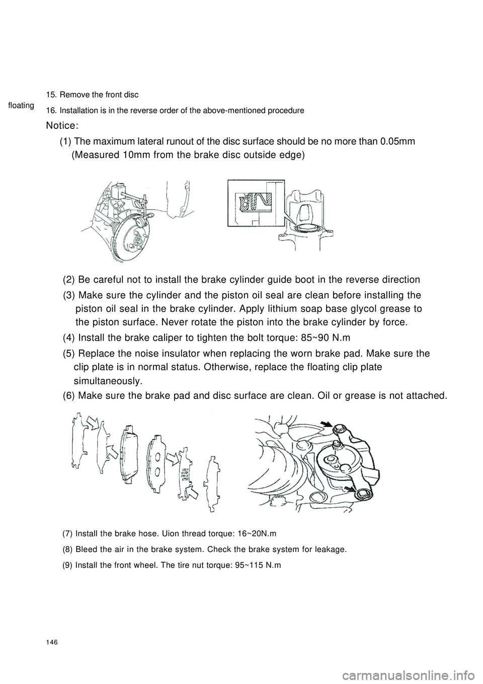
14615. Remove the front disc
16. Installation is in the reverse order of the above-mentioned procedure
Notice:
(1) The maximum lateral runout of the disc surface should be no more than 0.05mm
(Measured 10mm from the brake disc outside edge)
(2) Be careful not to install the brake cylinder guide boot in the reverse direction
(3) Make sure the cylinder and the piston oil seal are clean before installing the
piston oil seal in the brake cylinder. Apply lithium soap base glycol grease to
the piston surface. Never rotate the piston into the brake cylinder by force.
(4) Install the brake caliper to tighten the bolt torque: 85~90 N.m
(5) Replace the noise insulator when replacing the worn brake pad. Make sure the
clip plate is in normal status. Otherwise, replace the floating clip plate
(6) Make sure the brake pad and disc surface are clean. Oil or grease is not attached.
(7) Install the brake hose. Uion thread torque: 16~20N.m
(8) Bleed the air in the brake system. Check the brake system for leakage.
(9) Install the front wheel. The tire nut torque: 95~115 N.msimultaneously.floating