Page 154 of 392
147Section 6 Rear BrakeComponents
Repairing1. Remove rear wheel
2. Drain the brake fluid
3. Remove the brake drum
(1) loose the parking brake handle
(2) Remove the cotter pin with a long nose pliers
(3) loose the spindle slot nut
Lower Return Spring
Oil Baffle Plate
Anchor Plate
Brake Bottom Plates
Left Cable Plate
Left Torsion Spring
Adjusting Pawl Shaft
Pin
Left Adjusting
Pawl
Left Adjusting
Plate
Brake Shoe I
Wheel Hub Bearing II
Rear Spindle Cap
Wheel Hub
Bearing I
Stop Washer
Wheel Hub
Bolt
Rear Ring Gear
Rear Brake Drum
Rear Spindle Cover
Brake Shoe I
Shoe Guide
Friction Shoe
Boot
Cup
Piston
Wheel Cylinder
Spring
Piston
BootCup
Parking Brake
Left Swing Arm
Rear Brake
Auto
Adjusting Lever
Adjusting Lever Spring
Return Spring
Page 156 of 392

1499. Remove the parking brake lever accessory
10. Inspect shoe lining thickness
Standard thickness: 4.0mm
Minimum thickness: 1.0mm
Replace the shoe if the lining thickness is less than the minimum or seriously worn.
11.Inspect brake drum and brake shoe lining for proper contact
If the contact between brake drum and shoe lining is improper, repair the lining with a brake shoe
grinder or replace the brake shoe.
12. Check brake wheel cylinder
Check the cylinder wall, piston cup for damage
13. Install brake wheel cylinder accessory
(1) Apply lithium soap base glycol grease to 2 brake wheel cylinder cups and pistons
(2) Replace two new cups and boots
14. Install the brake wheel cylinder
Brake wheel cylinder set bolt torque: 9~13 N.m
15. Apply high temperature grease
Apply high temperature grease to the contact surface of anchor
plate hole and pin. Smear a thin layer grease to back plate.
16. Install parking brake swing arm and other accessories
17. Install brake shoe I, II
18. Install brake shoe return spring
Page 162 of 392

155Section 8 Parking Brake SystemProblem symptoms tableUse the table below to help you find the cause of the problem. The numbers indicate the priority of the likely
cause of the problem. Check each part in order. If necessary, replace these parts.Parking brake operating handle
Components1. Parking Brake Handle 2. Flat-headed Rivet 3. Pin Shaft 4. Flat-headed Rivet 5. Parking
Ratchet Pawl 6. Ratchet Plate 7. Connecting Lever 8. Return Spring 9. Plastic Bush
10. Adjusting Nut 11. Hex Bolt Spring Washer Compo. 12. Control Lever Boot Assembly
13. Equalizer14. Flat-headed Rivet15. Adjusting BoltAdjustment1. Check the parking brake handle stroke
Parking brake handle stroke: the vehicle is in reliable brake when pulling the parking brake handle up to
4~7 clicks and the brake lamp is ON. The maximum control force should be no more than 196N.
The wheel can turn freely when fully releasing the parking brake handle. Otherwise, please adjust it.
2. Parking brake handle stroke
(1) Remove parking brake handle bushing
(2) Remove the rear auxiliary console assembly
(3) Turn the adjusting nut to the right position and make sure the brake handle stroke is as specifiedSymptom Suspect area1. P a rking bra ke ha ndle (out of a djustme nt)2. Parking brake cable (stuck)3. Parking brake shoe clearance (out of adjustment)4. P a rking bra ke shoes lining (crac ke d or distortion)5. Return or tension spring (damaged) Brake Stagnation
Page 163 of 392
156(4) Install auxiliary console rear assembly
(5) install the parking brake handle bushingParking brake cableComponents
Replacement1. Remove parking brake control lever boot
2. Remove auxiliary console rear assembly
3. Remove left, right parking brake cable assembly
(1) loose the adjusting nut. Separate left, right parking brake cable and parking brake control lever
assembly
(2) remove parking brake cable retaining clip
(3) remove the rear wheel
(4) remove the brake drum
(5) remove the parking brake cable from parking brake swing arm in the rear brake
4. Install the left, right parking brake cable assembly in the reverse order of the removal
Notice: check the parking brake handle stroke. Re-adjust the parking brake handle
stroke as specified in adjustment.Pull RodEqualizerM6 x 16 Adjusting NutParking
Brake CableBody ClipRubber RingM6 x 16 Bolt Compo.Adjusting Nut
Page 349 of 392

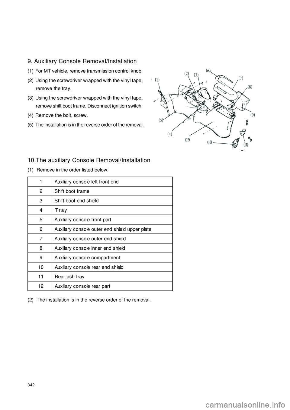
3429. Auxiliary Console Removal/Installation
(1) For MT vehicle, remove transmission control knob.
(2) Using the screwdriver wrapped with the vinyl tape,
remove the tray.
(3) Using the screwdriver wrapped with the vinyl tape,
remove shift boot frame. Disconnect ignition switch.
(4) Remove the bolt, screw.
(5) The installation is in the reverse order of the removal.
10.The auxiliary Console Removal/Installation
(1) Remove in the order listed below.
(2) The installation is in the reverse order of the removal.11
2 3
4 5 6
7
8
9
10
11 121 Au x iliar y c o n s o le lef t f r o n t e n d
2 Shift boot frame
3 Shift boot end shield
4Tray
5 Au x iliar y c o n s o le f r o n t p ar t
6 Au x iliar y c o n s o le o u t e r e n d s h ie ld u p p e r p lat e
7 Au x iliar y c o n s o le o u t e r e n d s h ie ld
8 Au x iliar y c o n s o le in n e r en d s h ield
9 Au x iliar y c o n s o le c o m p ar t m e n t
1 0 Au x iliar y c o n s o le r e ar e n d s h ie ld
11 Rear ash tray
1 2 Au x iliar y c o n s o le r e ar p a r t
Page:
< prev 1-8 9-16 17-24