Page 97 of 273

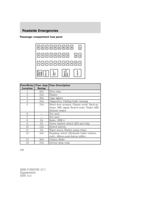
If the parking brake is applied due to low air pressure, immediate service
is required to the parking brake system.
Parking brake warning system
If the park brake light blinks and a chime sounds when pulling the yellow
control knob out, this indicates the parking brake is not functioning
properly; seek service for the parking brake immediately.
The light will blink and the chime will sound until the yellow control
knob is pushed in or approximately eight minutes have passed. If the
yellow control knob is pulled out again, the light will blink and the chime
will sound as a reminder that immediate service is required to the
parking brake system.
Releasing spring manually
Do not attempt to disassemble the parking brake chamber under
any circumstances. The high spring load may cause serious
injury.
If air pressure is released from the spring brake chamber the power
spring applies the brake and, unless air pressure can be re-established,
the spring brake must be released as follows in order to move the
vehicle.
Block the wheels to help prevent the vehicle from moving.
Unexpected and possibly sudden vehicle movement may occur if
these precautions are not taken.
2008 F-650/750(f67)
Supplement
USA(fus)
Driving
96
Page 98 of 273
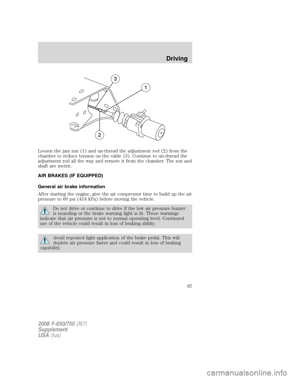
Loosen the jam nut (1) and un-thread the adjustment rod (2) from the
chamber to reduce tension on the cable (3). Continue to un-thread the
adjustment rod all the way and remove it from the chamber. The nut and
shaft are metric.
AIR BRAKES (IF EQUIPPED)
General air brake information
After starting the engine, give the air compressor time to build up the air
pressure to 60 psi (414 kPa) before moving the vehicle.
Do not drive or continue to drive if the low air pressure buzzer
is sounding or the brake warning light is lit. These warnings
indicate that air pressure is not to normal operating level. Continued
use of the vehicle could result in loss of braking ability.
Avoid repeated light application of the brake pedal. This will
deplete air pressure faster and could result in loss of braking
capability.
2008 F-650/750(f67)
Supplement
USA(fus)
Driving
97
Page 99 of 273

Periodically check the air pressure
gauge while driving. Pressure should
range between approximately
100–125 psi (690–862 kPa). The air
compressor governor cut-in and
cut-out pressure settings are preset
at the factory and are not
adjustable.
When air pressure is insufficient
(below 60 psi [414 kPa]), a warning
light illuminates and a buzzer
sounds when the ignition is in the
ON position.
This condition may be caused by excessive brake applications depleting
the system air pressure. If this condition occurs, stop driving the vehicle
until the compressor has fully recharged the air system.
Do not move the vehicle when the air pressure is insufficient
because the brake system may be inoperative.
Select a gear ratio to help slow your vehicle before descending grades.
Supplement with brakes as required to safely slow the vehicle and avoid
overspeeding the engine.
Air chamber stroke indication
Air chamber push rods have orange stroke indicator markers that warn
when the braking system requires adjustment or repair. The orange
stripe is painted on the air chamber push rod at the slack adjuster stroke
dimension which requires service when visible during brake application.
Air brake inspection and adjustment or repairs should be performed by a
qualified service technician in accordance with the instructions in the
service manual.
2008 F-650/750(f67)
Supplement
USA(fus)
Driving
98
Page 100 of 273

Cam brakes - automatic slack adjusters
Standard air brakes (cam) are
equipped with automatic brake
adjusters. Automatic adjustment
occurs during brake applications.
Inspect brakes for proper
adjustment at the intervals listed in
theScheduled Maintenance Guide
chapter.
Do not manually adjust the
automatic slack adjusters to
correct excessive pushrod stroke
as it may result in reduced brake
effectiveness and a vehicle crash.
Excessive pushrod stroke
indicates that a problem exists
with the automatic adjuster, with
the installation of the adjuster, or
with foundation brake components
that manual adjustment will not
remedy. Seek service from a
qualified facility for excessive
pushrod stroke.
Emergency air brake
All vehicles are equipped with a dual brake system. In the unlikely event
of a failure of one system, the second system will function for emergency
stopping. These systems are all controlled by the brake pedal in the
same manner as for normal stops.
Do not continue to operate the vehicle with a failure of one of
the brake systems. Take the vehicle to your dealer for service
immediately.
Air brake reservoir draining
Failure to drain air brake reservoirs can result in a reduction or
loss of braking ability due to fluid accumulation in the reservoir
and/or possible freeze-up during cold weather.
2008 F-650/750(f67)
Supplement
USA(fus)
Driving
99
Page 101 of 273

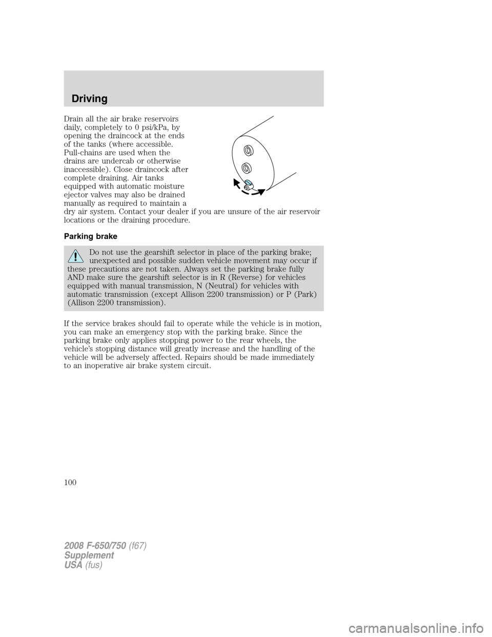
Drain all the air brake reservoirs
daily, completely to 0 psi/kPa, by
opening the draincock at the ends
of the tanks (where accessible.
Pull-chains are used when the
drains are undercab or otherwise
inaccessible). Close draincock after
complete draining. Air tanks
equipped with automatic moisture
ejector valves may also be drained
manually as required to maintain a
dry air system. Contact your dealer if you are unsure of the air reservoir
locations or the draining procedure.
Parking brake
Do not use the gearshift selector in place of the parking brake;
unexpected and possible sudden vehicle movement may occur if
these precautions are not taken. Always set the parking brake fully
AND make sure the gearshift selector is in R (Reverse) for vehicles
equipped with manual transmission, N (Neutral) for vehicles with
automatic transmission (except Allison 2200 transmission) or P (Park)
(Allison 2200 transmission).
If the service brakes should fail to operate while the vehicle is in motion,
you can make an emergency stop with the parking brake. Since the
parking brake only applies stopping power to the rear wheels, the
vehicle’s stopping distance will greatly increase and the handling of the
vehicle will be adversely affected. Repairs should be made immediately
to an inoperative air brake system circuit.
2008 F-650/750(f67)
Supplement
USA(fus)
Driving
100
Page 102 of 273

Parking brake control (knob)
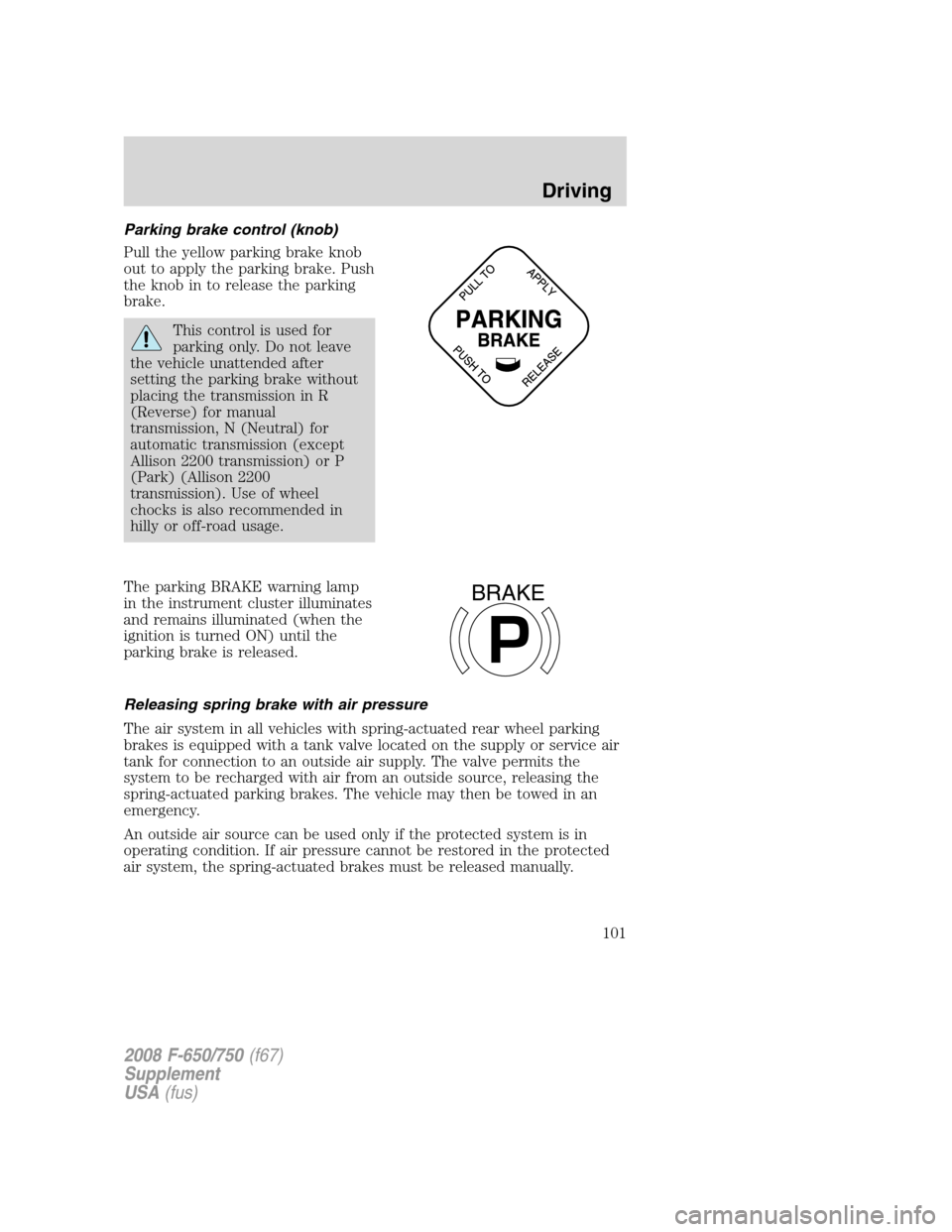
Pull the yellow parking brake knob
out to apply the parking brake. Push
the knob in to release the parking
brake.
This control is used for
parking only. Do not leave
the vehicle unattended after
setting the parking brake without
placing the transmission in R
(Reverse) for manual
transmission, N (Neutral) for
automatic transmission (except
Allison 2200 transmission) or P
(Park) (Allison 2200
transmission). Use of wheel
chocks is also recommended in
hilly or off-road usage.
The parking BRAKE warning lamp
in the instrument cluster illuminates
and remains illuminated (when the
ignition is turned ON) until the
parking brake is released.
Releasing spring brake with air pressure
The air system in all vehicles with spring-actuated rear wheel parking
brakes is equipped with a tank valve located on the supply or service air
tank for connection to an outside air supply. The valve permits the
system to be recharged with air from an outside source, releasing the
spring-actuated parking brakes. The vehicle may then be towed in an
emergency.
An outside air source can be used only if the protected system is in
operating condition. If air pressure cannot be restored in the protected
air system, the spring-actuated brakes must be released manually.
P
BRAKE
2008 F-650/750(f67)
Supplement
USA(fus)
Driving
101
Page 103 of 273

Releasing spring brake manually
Do not attempt to disassemble the parking brake chamber under
any circumstances. The high spring load may cause serious
injury if the chamber clamps are removed.
If air pressure is released from the spring brake chamber the power
spring applies the brake and, unless air pressure can be re-established,
the spring brake must be released as follows in order to move the
vehicle.
Block the wheels to help prevent the vehicle from moving.
Unexpected and possibly sudden vehicle movement may occur if
these precautions are not taken.
Impact wrenches should not be used as they may damage the piston and
prevent proper caging of the spring. Do not apply more than 50 lb. ft.
(68 N•m) torque to the release bolt nut.
1. Remove the stud tool and nut
from the carrying pocket on the
brake chamber assembly.
2. Remove the access plug from the
end of the spring chamber.
3. Insert the release stud through
the opening in the chamber and into
the spring pressure plate.
2008 F-650/750(f67)
Supplement
USA(fus)
Driving
102
Page 104 of 273

4. Turn the release stud one-quarter
turn to engage the stud tangs with
the slot in the pressure plate. Keep
the stud engaged and install the nut
on the release stud.
5. Tighten the nut until the spring is
fully caged and the brakes are
released. Do not loosen or remove
the release stud and nut unless the brake chamber is completely
assembled and is securely clamped.
6. When the air pressure is restored, unscrew and remove the release
stud and install in the carrying pocket. Install the access plug.
EXHAUST BRAKE (IF EQUIPPED)
Note:The exhaust brake is
intended to help control vehicle
speed; it is not a vehicle stopping
device.
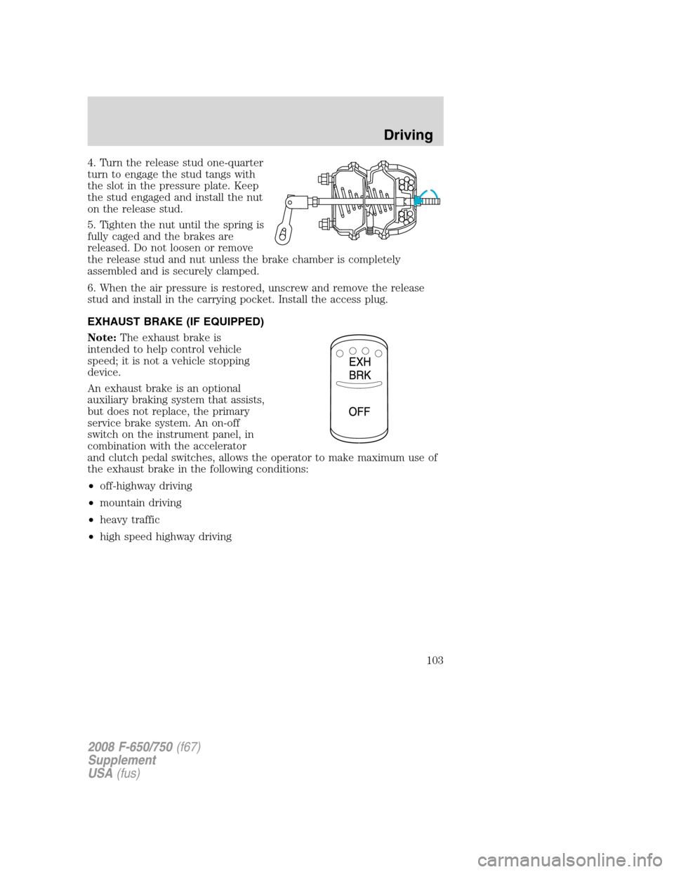
An exhaust brake is an optional
auxiliary braking system that assists,
but does not replace, the primary
service brake system. An on-off
switch on the instrument panel, in
combination with the accelerator
and clutch pedal switches, allows the operator to make maximum use of
the exhaust brake in the following conditions:
•off-highway driving
•mountain driving
•heavy traffic
•high speed highway driving
2008 F-650/750(f67)
Supplement
USA(fus)
Driving
103