Page 5 of 74

TABLE OF CONTENTESSAFETY INFORMATION .................... 1-1
DESCRIPTION ................................... 2-1Left view ........................................ 2 - 1
Right view ...................................... 2 - 2
Controls and instruments ............. 2 - 3
INSTRUMENT AND CONTROL
FUNCTIONS ....................................... 3-1 Main switch/steering lock ............. 3 - 1
Indicator and warning lights ........ 3 - 2
Speedometer ................................. 3 - 2
Tachometer .................................... 3 - 3
Multi-function display ................... 3 - 3
Handlebar switches ...................... 3 - 4
Clutch lever ................................... 3 - 5
Shift pedal ..................................... 3 - 6
Brake lever .................................... 3 - 6
Brake pedal ................................... 3 - 6
Fuel tank cap ................................. 3 - 7
Fuel ................................................ 3 - 7
Catalytic converter ........................ 3 - 8
Seat ................................................ 3 - 9
Helmet holder ................................ 3 - 9
Storage compartment .................3-10
Adjusting the shock aborber
assemblies ............................... 3-10
Luggage strap holders ...............3-11
Sidestand ..................................... 3-11
Ignition circuit cut-off system .....3-12 PRE-OPERATION CHECKS .............. 4-1
Pre-operation check list ............... 4 - 2
OPERATION AND IMPORTANT
RIDING POINTS ................................. 5-1 Starting the engine ....................... 5 - 1
Shifting ........................................... 5 - 2
Tips for reducing fuel
consumption .............................. 5 - 3
Engine break-in ............................ 5 - 3
Parking .......................................... 5 - 4
PERIODIC MAINTENANCE AND
MINOR REPAIR .................................. 6-1 Owner’s tool kit .............................. 6 - 1
Periodic maintenance and lubrication chart ......................... 6 - 2
Removing and installing the cowling and panels ................... 6 - 6
Checking the spark plug .............. 6 - 7
Engine oil and oil filter element ... 6-8
Cleaning the air filter element ... 6-11
Checking the engine idling
speed ........................................ 6-12
Checking the throttle cable free play .................................... 6-12
Valve clearance .. ........................6-12
Tires ............................................. 6-13
Cast wheels ................................. 6-15
Adjusting the clutch lever free play .................................... 6-15Adjusting the brake pedal
position and free play .............6-16
Adjusting the rear brake light switch ........................................ 6-17
Checking the front brake pads
and rear brake shoes ..............6-17
Checking the front brake fluid level .......................................... 6-18
Changing the brake fluid ...........6-18
Drive chain slack ........................6-19
Cleaning and lubricating the
drive chain ............................... 6-20
Checking and lubricating the cables ....................................... 6-21
Checking and lubricating the throttle grip and cable .............6-21
Checking and lubricating the
brake and clutch levers ...........6-21
Checking and lubricating the brake and shift pedals ............6-22
Checking and lubricating the sidestand .................................. 6-22
Lubricating the rear
suspension .............................. 6-23
Checking the front fork ...............6-23
Checking the steering ................6-24
Checking the wheel bearings ....6-24
Battery .......................................... 6-24
Replacing the fuses ....................6-26
Replacing the headlight bulb ....6-27
Replacing a turn signal light bulb or the tail/brake light bulb .......6-28
indice.pmd 24/1/2007, 14:37
1
Page 11 of 74
2-1
2
DESCRIPTION
EAU10410
Left view1. Idle adjusting screw
2. Battery
3. Main fuse
4. Fuse box
5. Storage compartment
6. Grab bar
7. Seat lock
8. Shift pedal
9. Engine oil drain bolt
cap 2.pmd24/1/2007, 14:37
1
Page 59 of 74

6-26
6
PERIODIC MAINTENANCE AND MINOR REPAIR
EAU23624
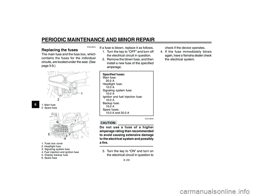
Replacing the fusesThe main fuse and the fuse box, which
contains the fuses for the individual
circuits, are located under the seat. (See
page 3-9.)
20
1
2
1. Main fuse
2. Spare fuse1. Fuse box cover
2. Headlight fuse
3. Signaling system fuse
4. Fuel injection and ignition fuse
5. Display backup fuse
6. Spare fuse
If a fuse is blown, replace it as follows.
1. Turn the key to “OFF” and turn off the electrical circuit in question.
2. Remove the blown fuse, and then install a new fuse of the specified
amperage.Specified fuses:
Main fuse:20.0 A
Headlight fuse: 10.0 A
Signaling system fuse:
10.0 A
Ignition and fuel injection fuse: 10.0 A
Backup fuse: 10.0 A
Spare fuses:
10.0 A and 20.0 A
ECA10640
Do not use a fuse of a higher
amperage rating than recommended
to avoid causing extensive damage
to the electrical system and possibly
a fire.3. Turn the key to “ON” and turn on
the electrical circuit in question to check if the device operates.
4. If the fuse immediately blows again, have a Yamaha dealer check
the electrical system.
cap 6.pmd 24/1/2007, 14:38
26
Page 72 of 74
8-3
SPECIFICATIONS
8
Headlight:Bulb type:Halogen bulbBulb voltage, wattage x quantityHeadlight: 12 V, 35 W/35.0 W x 1
Tail brake light: 12 V, 5.0 W/21.0 W x 1
Front turn signal light:
12 V, 10.0 W x 2
Rear turn signal light:
12 V, 10.0 W x 2
Position light: 12 V, 5.0 W
Meter lighting:
14 V, 2.0 W x 2
Neutral indicator light:
14 V, 1.4 W x 1
Turn signal indicator light: 14 V, 1.4 W x 2
High beam indicator light:
14 V, 1.4 W x 1
Engine trouble warning light:
LEDFuses:Main fuse:20.0 A
Headlight fuse: 10.0 A
Signaling system fuse:
10.0 A
Ignition and fuel injection fuse:
10.0 A Backup fuse:
10.0 A
Spare fuses:
10.0 A and 20.0 A
cap 8.pmd 24/1/2007, 14:38
3