2007 TOYOTA SIENNA 1299
[x] Cancel search: 1299Page 220 of 3000

SS–26SERVICE SPECIFICATIONS – U151E AUTOMATIC TRANSAXLE
SS
3th gear Lock-up ON 68 to 75 km/h (42 to 47 mph)
Lock-up
OFF65 to 72 km/h (43 to 45 mph)
Oil pump
Body clearance STD 0.10 to 0.17 mm (0.0039 to 0.0067 in.)
Max. 0.17 mm (0.0067 in.)
Tip clearance STD 0.07 to 0.15 mm (0.0028 to 0.0059 in.)
Max. 0.15 mm (0.0059 in.)
Side clearance STD 0.02 to 0.05 mm (0.0008 to 0.0020 in.)
Max. 0.05 mm (0.0020 in.)
Drive gear thickness Mark
A 11.690 to 11.699 mm (0.4602 to 0.4606 in.)
B 11.700 to 11.709 mm (0.4606 to 0.4610 in.)
C 11.710 to 11.720 mm (0.4610 to 0.4614 in.)
D 11.721 to 11.730 mm (0.4615 to 0.4618 in.)
E 11.731 to 11.740 mm (0.4619 to 0.4622 in.)
Driven gear thickness Mark
A 11.690 to 11.699 mm (0.4602 to 0.4606 in.)
B 11.700 to 11.709 mm (0.4606 to 0.4610 in.)
C 11.710 to 11.720 mm (0.4610 to 0.4614 in.)
D 11.721 to 11.730 mm (0.4615 to 0.4618 in.)
E 11.731 to 11.740 mm (0.4619 to 0.4622 in.)
Pump body bushing inside diameter STD 38.113 to 38.138 mm (1.50050 to 1.50149 in.)
Max. 38.188 mm (1.50346 in.)
Stator shaft bushing inside diameter STD 21.500 to 21.526 mm (0.84646 to 0.84748 in.)
Max. 21.57 mm (0.8492 in.)
Multiple disc clutch
Inside diameter STD 23.025 to 23.045 mm (0.9065 to 0.9073 in.)
Max. 23.09 mm (0.9091 in.)
Forward clutch
Pack clearance1.00 to 1.25 mm (0.0394 to 0.4921 in.)
Return spring free length26.74 mm (1.0528 in.)
Flange thickness Mark
1 3.00 mm (0.1181 in.)
2 3.15 mm (0.1240 in.)
3 3.30 mm (0.1299 in.)
4 3.45 mm (0.1358 in.)
5 3.60 mm (0.1417 in.)
Reverse clutch
Pack clearance:0.60 to 0.82 mm (0.02362 to 0.03228 in.)
Flange thickness Mark
1 3.0 mm (0.118 in.)
2 3.1 mm (0.122 in.)
3 3.2 mm (0.126 in.)
4 3.3 mm (0.130 in.)
5 3.4 mm (0.134 in.)
6 3.5 mm (0.138 in.)
7 3.6 mm (0.142 in.)
Page 225 of 3000

SS–32SERVICE SPECIFICATIONS – U151F AUTOMATIC TRANSAXLE
SS
Manual down shift speed
3 146 to 157 km/h (91 to 98 mph)
2 90 to 96 km/h (56 to 60 mph)
1 39 to 44 km/h (24 to 27 mph)
Lock-up schedule (Throttle valve opening 5%)
5th gear Lock-up ON 63 to 70 km/h (39 to 43 mph)
Lock-up
OFF61 to 68 km/h (38 to 42 mph)
4th gear Lock-up ON 101 to 107 km/h (63 to 66 mph)
Lock-up
OFF98 to 104 km/h (61 to 65 mph)
3th gear Lock-up ON 63 to 70 km/h (39 to 43 mph)
Lock-up
OFF61 to 67 km/h (38 to 42 mph)
Oil pump
Body clearance STD 0.10 to 0.17 mm (0.0039 to 0.0067 in.)
Max. 0.17 mm (0.0067 in.)
Tip clearance STD 0.07 to 0.15 mm (0.0028 to 0.0059 in.)
Max. 0.15 mm (0.0059 in.)
Side clearance STD 0.02 to 0.05 mm (0.0008 to 0.0020 in.)
Max. 0.05 mm (0.0020 in.)
Drive gear thickness Mark
A 11.690 to 11.699 mm (0.4602 to 0.4606 in.)
B 11.700 to 11.709 mm (0.4606 to 0.4610 in.)
C 11.710 to 11.720 mm (0.4610 to 0.4614 in.)
D 11.721 to 11.730 mm (0.4615 to 0.4618 in.)
E 11.731 to 11.740 mm (0.4619 to 0.4622 in.)
Driven gear thickness Mark
A 11.690 to 11.699 mm (0.4602 to 0.4606 in.)
B 11.700 to 11.709 mm (0.4606 to 0.4610 in.)
C 11.710 to 11.720 mm (0.4610 to 0.4614 in.)
D 11.721 to 11.730 mm (0.4615 to 0.4618 in.)
E 11.731 to 11.740 mm (0.4619 to 0.4622 in.)
Pump body bushing inside diameter STD 38.113 to 38.138 mm (1.50050 to 1.50149 in.)
Max. 38.188 mm (1.50346 in.)
Stator shaft bushing inside diameter STD 21.500 to 21.526 mm (0.84646 to 0.84748 in.)
Max. 21.57 mm (0.8492 in.)
Multiple disc clutch
Inside diameter STD 23.025 to 23.045 mm (0.9065 to 0.9073 in.)
Max. 23.09 mm (0.9091 in.)
Forward clutch
Pack clearance1.00 to 1.25 mm (0.0394 to 0.4921 in.)
Return spring free length26.74 mm (1.0528 in.)
Flange thickness Mark
1 3.00 mm (0.1181 in.)
2 3.15 mm (0.1240 in.)
3 3.30 mm (0.1299 in.)
4 3.45 mm (0.1358 in.)
5 3.60 mm (0.1417 in.)
Page 848 of 3000
MULTIPLEX COMMUNICATION – MULTIPLEX COMMUNICATION SYSTEMMP–5
MP
TERMINALS OF ECU
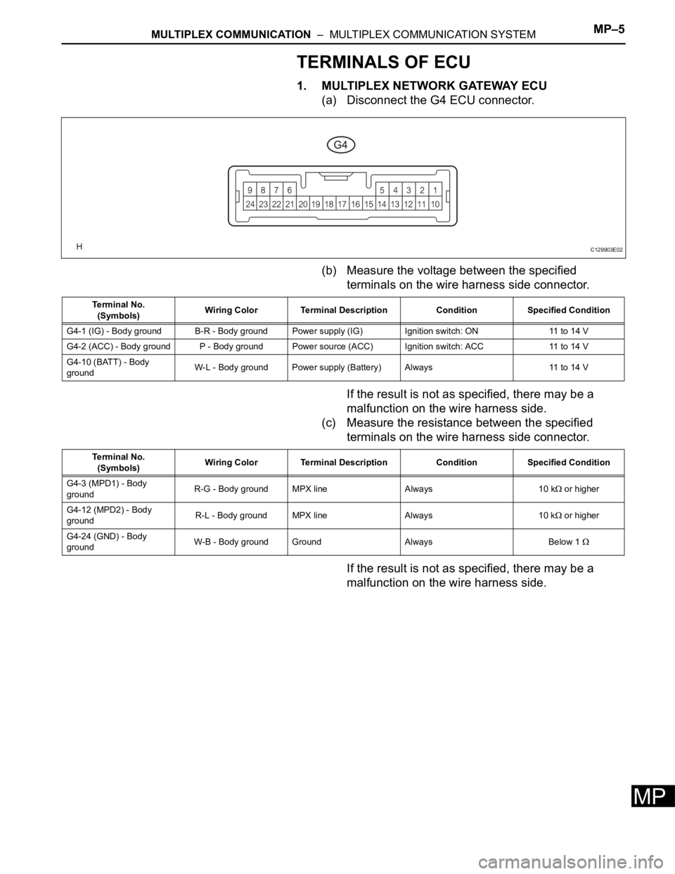
1. MULTIPLEX NETWORK GATEWAY ECU
(a) Disconnect the G4 ECU connector.
(b) Measure the voltage between the specified
terminals on the wire harness side connector.
If the result is not as specified, there may be a
malfunction on the wire harness side.
(c) Measure the resistance between the specified
terminals on the wire harness side connector.
If the result is not as specified, there may be a
malfunction on the wire harness side.
C129903E02
Terminal No.
(Symbols)Wiring Color Terminal Description Condition Specified Condition
G4-1 (IG) - Body ground B-R - Body ground Power supply (IG) Ignition switch: ON 11 to 14 V
G4-2 (ACC) - Body ground P - Body ground Power source (ACC) Ignition switch: ACC 11 to 14 V
G4-10 (BATT) - Body
groundW-L - Body ground Power supply (Battery) Always 11 to 14 V
Terminal No.
(Symbols)Wiring Color Terminal Description Condition Specified Condition
G4-3 (MPD1) - Body
groundR-G - Body ground MPX line Always 10 k
or higher
G4-12 (MPD2) - Body
groundR-L - Body ground MPX line Always 10 k
or higher
G4-24 (GND) - Body
groundW-B - Body ground Ground Always Below 1
Page 1324 of 3000
ST–102GR-FE STARTING – STARTER
ST
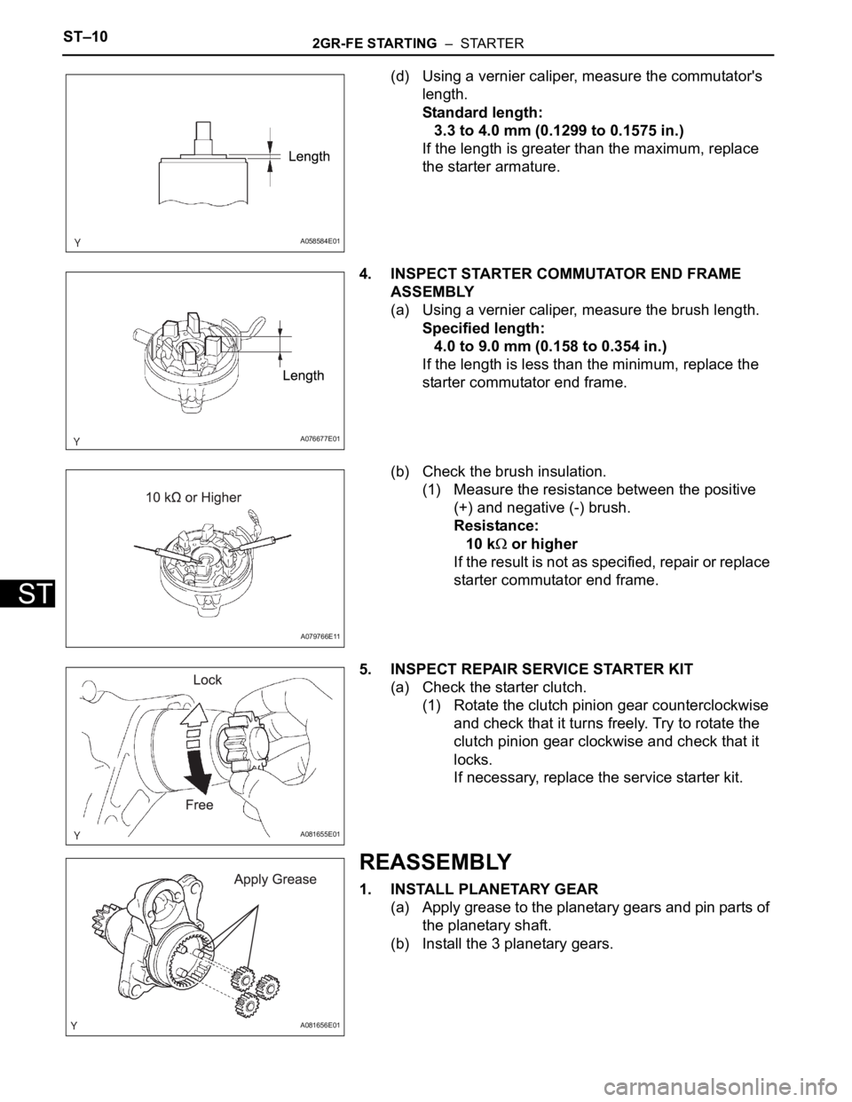
(d) Using a vernier caliper, measure the commutator's
length.
Standard length:
3.3 to 4.0 mm (0.1299 to 0.1575 in.)
If the length is greater than the maximum, replace
the starter armature.
4. INSPECT STARTER COMMUTATOR END FRAME
ASSEMBLY
(a) Using a vernier caliper, measure the brush length.
Specified length:
4.0 to 9.0 mm (0.158 to 0.354 in.)
If the length is less than the minimum, replace the
starter commutator end frame.
(b) Check the brush insulation.
(1) Measure the resistance between the positive
(+) and negative (-) brush.
Resistance:
10 k
or higher
If the result is not as specified, repair or replace
starter commutator end frame.
5. INSPECT REPAIR SERVICE STARTER KIT
(a) Check the starter clutch.
(1) Rotate the clutch pinion gear counterclockwise
and check that it turns freely. Try to rotate the
clutch pinion gear clockwise and check that it
locks.
If necessary, replace the service starter kit.
REASSEMBLY
1. INSTALL PLANETARY GEAR
(a) Apply grease to the planetary gears and pin parts of
the planetary shaft.
(b) Install the 3 planetary gears.
A058584E01
A076677E01
A079766E11
A081655E01
A081656E01
Page 1333 of 3000
ST–102GR-FE STARTING – STARTER
ST
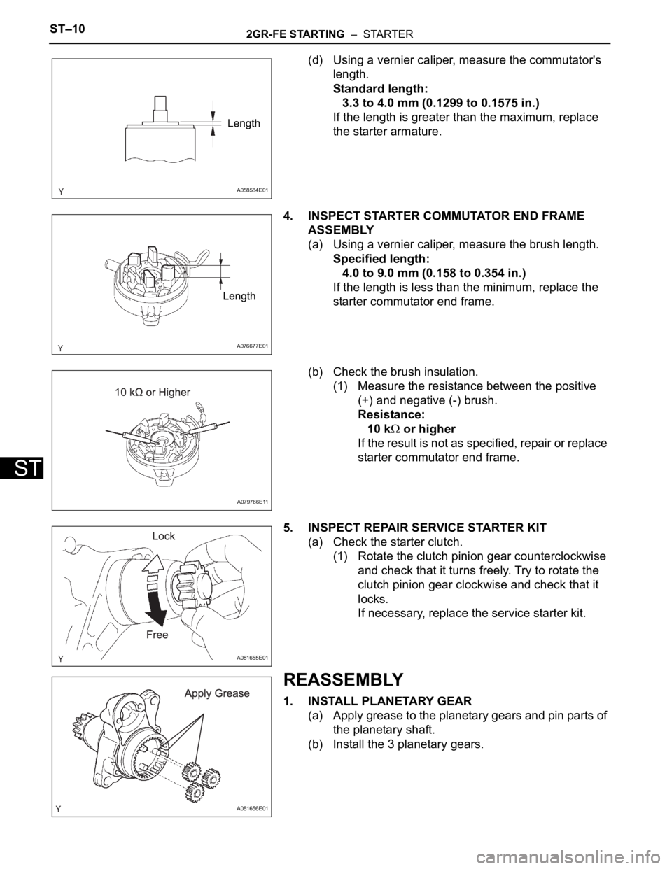
(d) Using a vernier caliper, measure the commutator's
length.
Standard length:
3.3 to 4.0 mm (0.1299 to 0.1575 in.)
If the length is greater than the maximum, replace
the starter armature.
4. INSPECT STARTER COMMUTATOR END FRAME
ASSEMBLY
(a) Using a vernier caliper, measure the brush length.
Specified length:
4.0 to 9.0 mm (0.158 to 0.354 in.)
If the length is less than the minimum, replace the
starter commutator end frame.
(b) Check the brush insulation.
(1) Measure the resistance between the positive
(+) and negative (-) brush.
Resistance:
10 k
or higher
If the result is not as specified, repair or replace
starter commutator end frame.
5. INSPECT REPAIR SERVICE STARTER KIT
(a) Check the starter clutch.
(1) Rotate the clutch pinion gear counterclockwise
and check that it turns freely. Try to rotate the
clutch pinion gear clockwise and check that it
locks.
If necessary, replace the service starter kit.
REASSEMBLY
1. INSTALL PLANETARY GEAR
(a) Apply grease to the planetary gears and pin parts of
the planetary shaft.
(b) Install the 3 planetary gears.
A058584E01
A076677E01
A079766E11
A081655E01
A081656E01
Page 1646 of 3000
U151E AUTOMATIC TRANSAXLE – FORWARD CLUTCHAX–243
AX
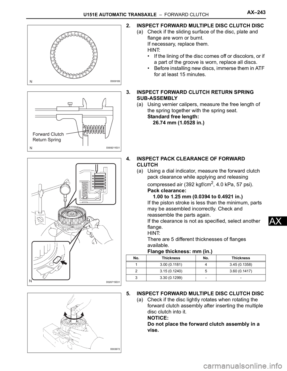
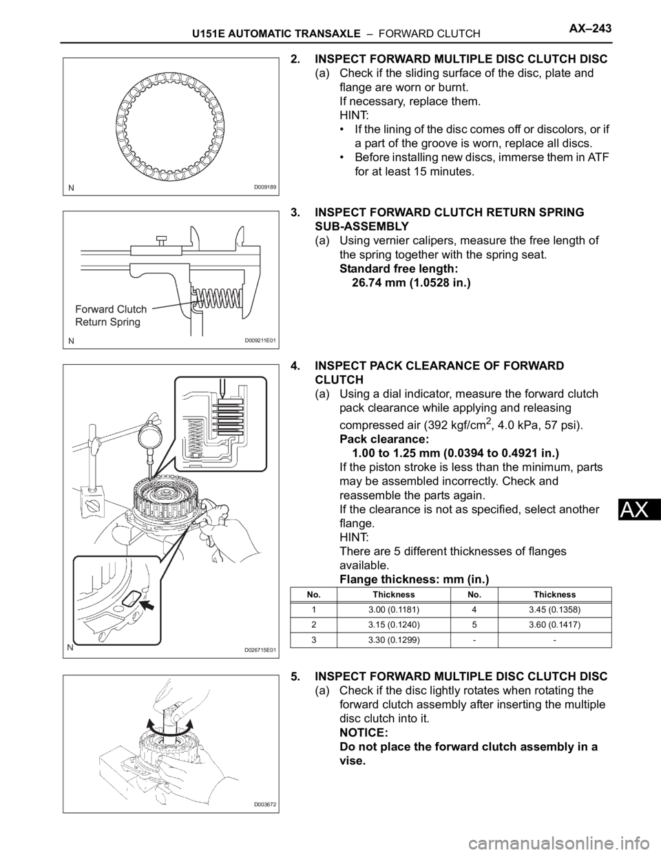
2. INSPECT FORWARD MULTIPLE DISC CLUTCH DISC
(a) Check if the sliding surface of the disc, plate and
flange are worn or burnt.
If necessary, replace them.
HINT:
• If the lining of the disc comes off or discolors, or if
a part of the groove is worn, replace all discs.
• Before installing new discs, immerse them in ATF
for at least 15 minutes.
3. INSPECT FORWARD CLUTCH RETURN SPRING
SUB-ASSEMBLY
(a) Using vernier calipers, measure the free length of
the spring together with the spring seat.
Standard free length:
26.74 mm (1.0528 in.)
4. INSPECT PACK CLEARANCE OF FORWARD
CLUTCH
(a) Using a dial indicator, measure the forward clutch
pack clearance while applying and releasing
compressed air (392 kgf/cm
2, 4.0 kPa, 57 psi).
Pack clearance:
1.00 to 1.25 mm (0.0394 to 0.4921 in.)
If the piston stroke is less than the minimum, parts
may be assembled incorrectly. Check and
reassemble the parts again.
If the clearance is not as specified, select another
flange.
HINT:
There are 5 different thicknesses of flanges
available.
Flange thickness: mm (in.)
5. INSPECT FORWARD MULTIPLE DISC CLUTCH DISC
(a) Check if the disc lightly rotates when rotating the
forward clutch assembly after inserting the multiple
disc clutch into it.
NOTICE:
Do not place the forward clutch assembly in a
vise.
D009189
D009211E01
D026715E01
No. Thickness No. Thickness
1 3.00 (0.1181) 4 3.45 (0.1358)
2 3.15 (0.1240) 5 3.60 (0.1417)
3 3.30 (0.1299) - -
D003672
Page 1655 of 3000
U151E AUTOMATIC TRANSAXLE – FORWARD CLUTCHAX–243
AX
2. INSPECT FORWARD MULTIPLE DISC CLUTCH DISC
(a) Check if the sliding surface of the disc, plate and
flange are worn or burnt.
If necessary, replace them.
HINT:
• If the lining of the disc comes off or discolors, or if
a part of the groove is worn, replace all discs.
• Before installing new discs, immerse them in ATF
for at least 15 minutes.
3. INSPECT FORWARD CLUTCH RETURN SPRING
SUB-ASSEMBLY
(a) Using vernier calipers, measure the free length of
the spring together with the spring seat.
Standard free length:
26.74 mm (1.0528 in.)
4. INSPECT PACK CLEARANCE OF FORWARD
CLUTCH
(a) Using a dial indicator, measure the forward clutch
pack clearance while applying and releasing
compressed air (392 kgf/cm
2, 4.0 kPa, 57 psi).
Pack clearance:
1.00 to 1.25 mm (0.0394 to 0.4921 in.)
If the piston stroke is less than the minimum, parts
may be assembled incorrectly. Check and
reassemble the parts again.
If the clearance is not as specified, select another
flange.
HINT:
There are 5 different thicknesses of flanges
available.
Flange thickness: mm (in.)
5. INSPECT FORWARD MULTIPLE DISC CLUTCH DISC
(a) Check if the disc lightly rotates when rotating the
forward clutch assembly after inserting the multiple
disc clutch into it.
NOTICE:
Do not place the forward clutch assembly in a
vise.
D009189
D009211E01
D026715E01
No. Thickness No. Thickness
1 3.00 (0.1181) 4 3.45 (0.1358)
2 3.15 (0.1240) 5 3.60 (0.1417)
3 3.30 (0.1299) - -
D003672
Page 1947 of 3000
U151F AUTOMATIC TRANSAXLE – FORWARD CLUTCHAX–247
AX
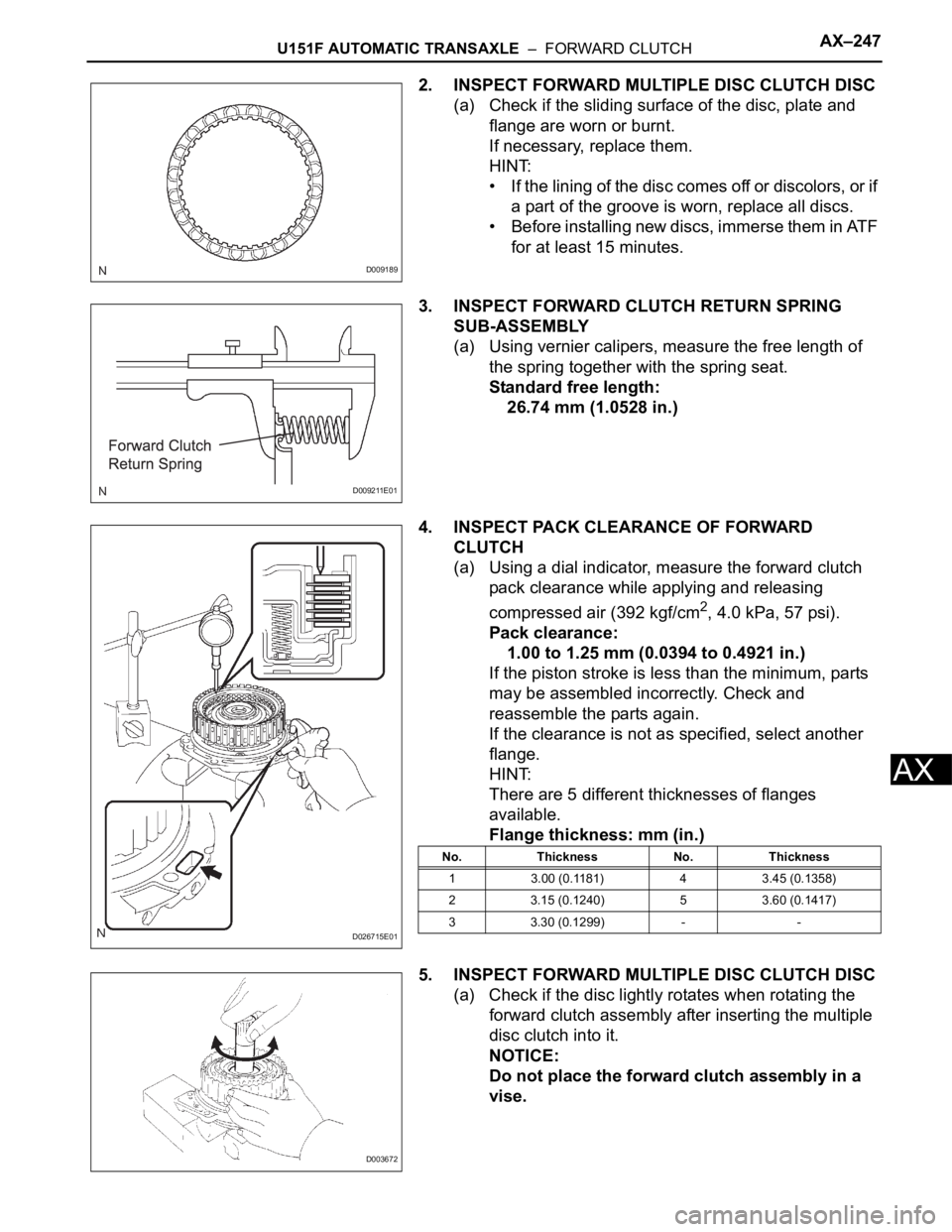
2. INSPECT FORWARD MULTIPLE DISC CLUTCH DISC
(a) Check if the sliding surface of the disc, plate and
flange are worn or burnt.
If necessary, replace them.
HINT:
• If the lining of the disc comes off or discolors, or if
a part of the groove is worn, replace all discs.
• Before installing new discs, immerse them in ATF
for at least 15 minutes.
3. INSPECT FORWARD CLUTCH RETURN SPRING
SUB-ASSEMBLY
(a) Using vernier calipers, measure the free length of
the spring together with the spring seat.
Standard free length:
26.74 mm (1.0528 in.)
4. INSPECT PACK CLEARANCE OF FORWARD
CLUTCH
(a) Using a dial indicator, measure the forward clutch
pack clearance while applying and releasing
compressed air (392 kgf/cm
2, 4.0 kPa, 57 psi).
Pack clearance:
1.00 to 1.25 mm (0.0394 to 0.4921 in.)
If the piston stroke is less than the minimum, parts
may be assembled incorrectly. Check and
reassemble the parts again.
If the clearance is not as specified, select another
flange.
HINT:
There are 5 different thicknesses of flanges
available.
Flange thickness: mm (in.)
5. INSPECT FORWARD MULTIPLE DISC CLUTCH DISC
(a) Check if the disc lightly rotates when rotating the
forward clutch assembly after inserting the multiple
disc clutch into it.
NOTICE:
Do not place the forward clutch assembly in a
vise.
D009189
D009211E01
D026715E01
No. Thickness No. Thickness
1 3.00 (0.1181) 4 3.45 (0.1358)
2 3.15 (0.1240) 5 3.60 (0.1417)
3 3.30 (0.1299) - -
D003672