Page 1818 of 3000
AX–132U151F AUTOMATIC TRANSAXLE – TRANSMISSION WIRE
AX
6. REMOVE TRANSMISSION WIRE
(a) Disconnect the transmission wire connector.
(b) Remove the bolt and transmission wire.
(c) Remove the O-ring from the transmission wire.
INSTALLATION
1. INSTALL TRANSMISSION WIRE
(a) Coat the O-ring of the transmission wire connector
with ATF and install it.
(b) Install the transmission wire with the bolt.
Torque: 5.4 N*m (55 kgf*cm, 48 ft.*lbf)
2. CONNECT TRANSMISSION WIRE
(a) Coat the O-ring of the ATF temperature sensor with
AT F.
(b) Install the ATF temperature sensor with the lock
plate and bolt.
Torque: 6.6 N*m (67 kgf*cm, 58 ft.*lbf)
(c) Connect the 7 shift solenoid valve connectors.
3. INSTALL AUTOMATIC TRANSAXLE OIL PAN SUB-
ASSEMBLY
(a) Install the 2 magnets in the oil pan.
(b) Apply seal packing to the 18 bolts.
Seal packing:
THREE BOND 2430 or equivalent
D030866
D030867
D030866
C091927E04
D030865
Page 1822 of 3000

AX–136U151F AUTOMATIC TRANSAXLE – VALVE BODY ASSEMBLY
AX
REMOVAL
1. REMOVE ENGINE UNDER COVER NO.1
2. DISCONNECT CABLE FROM NEGATIVE BATTERY
TERMINAL
3. DRAIN AUTOMATIC TRANSAXLE FLUID (See page
AX-131)
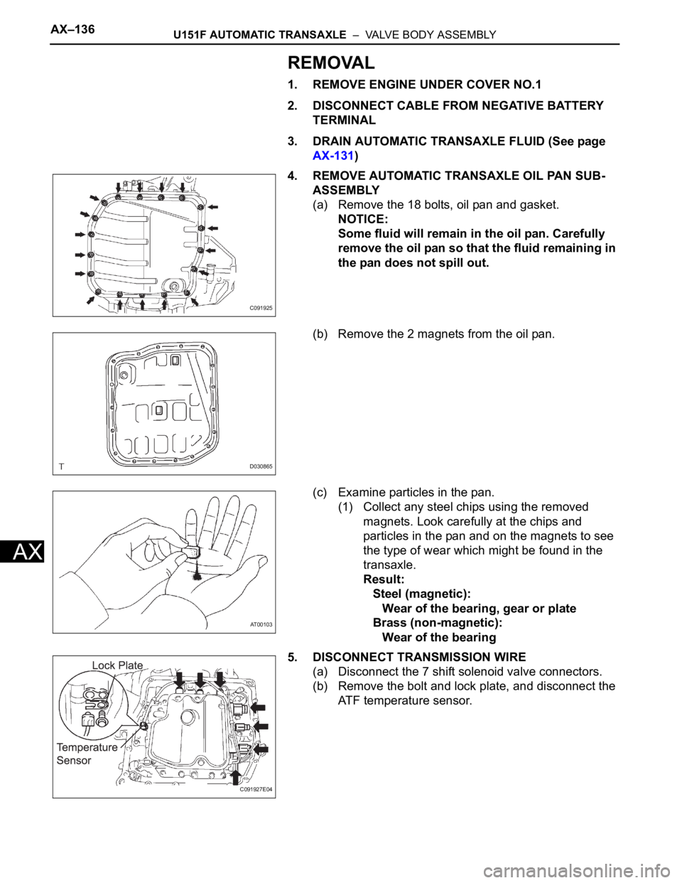
4. REMOVE AUTOMATIC TRANSAXLE OIL PAN SUB-
ASSEMBLY
(a) Remove the 18 bolts, oil pan and gasket.
NOTICE:
Some fluid will remain in the oil pan. Carefully
remove the oil pan so that the fluid remaining in
the pan does not spill out.
(b) Remove the 2 magnets from the oil pan.
(c) Examine particles in the pan.
(1) Collect any steel chips using the removed
magnets. Look carefully at the chips and
particles in the pan and on the magnets to see
the type of wear which might be found in the
transaxle.
Result:
Steel (magnetic):
Wear of the bearing, gear or plate
Brass (non-magnetic):
Wear of the bearing
5. DISCONNECT TRANSMISSION WIRE
(a) Disconnect the 7 shift solenoid valve connectors.
(b) Remove the bolt and lock plate, and disconnect the
ATF temperature sensor.
C091925
D030865
AT00103
C091927E04
Page 1827 of 3000

U151F AUTOMATIC TRANSAXLE – VALVE BODY ASSEMBLYAX–141
AX
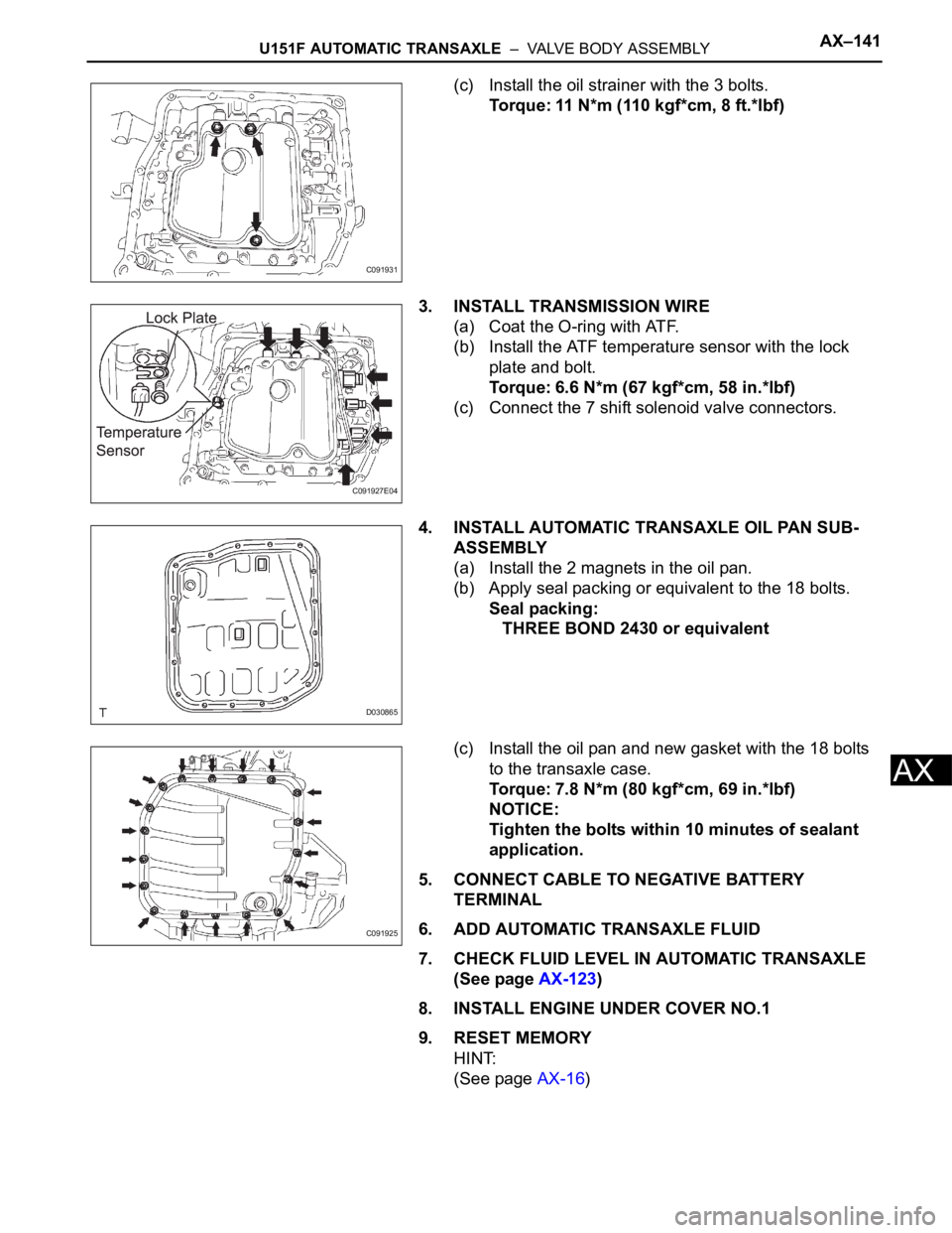
(c) Install the oil strainer with the 3 bolts.
Torque: 11 N*m (110 kgf*cm, 8 ft.*lbf)
3. INSTALL TRANSMISSION WIRE
(a) Coat the O-ring with ATF.
(b) Install the ATF temperature sensor with the lock
plate and bolt.
Torque: 6.6 N*m (67 kgf*cm, 58 in.*lbf)
(c) Connect the 7 shift solenoid valve connectors.
4. INSTALL AUTOMATIC TRANSAXLE OIL PAN SUB-
ASSEMBLY
(a) Install the 2 magnets in the oil pan.
(b) Apply seal packing or equivalent to the 18 bolts.
Seal packing:
THREE BOND 2430 or equivalent
(c) Install the oil pan and new gasket with the 18 bolts
to the transaxle case.
Torque: 7.8 N*m (80 kgf*cm, 69 in.*lbf)
NOTICE:
Tighten the bolts within 10 minutes of sealant
application.
5. CONNECT CABLE TO NEGATIVE BATTERY
TERMINAL
6. ADD AUTOMATIC TRANSAXLE FLUID
7. CHECK FLUID LEVEL IN AUTOMATIC TRANSAXLE
(See page AX-123)
8. INSTALL ENGINE UNDER COVER NO.1
9. RESET MEMORY
HINT:
(See page AX-16)
C091931
C091927E04
D030865
C091925
Page 1858 of 3000
U151F AUTOMATIC TRANSAXLE – AUTOMATIC TRANSAXLE UNITAX–183
AX
9. INSPECT TRANSMISSION OIL CLEANER MAGNET
(a) Remove the magnets and use them to collect any
steel chips. Examine the chips and particles in the
pan and on the magnet to determine what type of
wear has occurred in the transaxle:
Result:
Steel (magnetic):
Wear of the bearing, gear and plate
Brass (non-magnetic):
Wear of the bushing
10. DISCONNECT TRANSMISSION WIRE
(a) Remove the 7 connectors from the shift solenoid
valves.
(b) Remove the bolt, lock plate and temperature
sensor.
11. REMOVE TRANSMISSION WIRE
(a) Remove the bolt and transmission wire from the
transaxle case.
12. REMOVE VALVE BODY OIL STRAINER ASSEMBLY
(a) Remove the 3 bolts and oil strainer.
(b) Remove the O-ring from the oil strainer.
AT00103E03
C091927E02
D003547E05
C091931
C091932E01
Page 1914 of 3000

U151F AUTOMATIC TRANSAXLE – AUTOMATIC TRANSAXLE UNITAX–231
AX
64. INSTALL TRANSAXLE CASE 2ND BRAKE GASKET
(a) Coat a new transaxle case 2nd brake gasket with
ATF, and install it to the transaxle case.
NOTICE:
Be sure not to damage the lip of the transaxle
case brake gasket when inserting the gasket to
the case. Apply sufficient ATF to the gasket
before installation. Be careful about the
direction of parts.
65. INSTALL GOVERNOR APPLY GASKET NO.1
(a) Coat a new governor apply gasket No.1 with ATF,
and install it to the transaxle case.
NOTICE:
Be sure not to damage the lip of the transaxle
case brake gasket when inserting the gasket to
the case. Apply sufficient ATF to the gasket
before installation. Be careful about the
direction of parts.
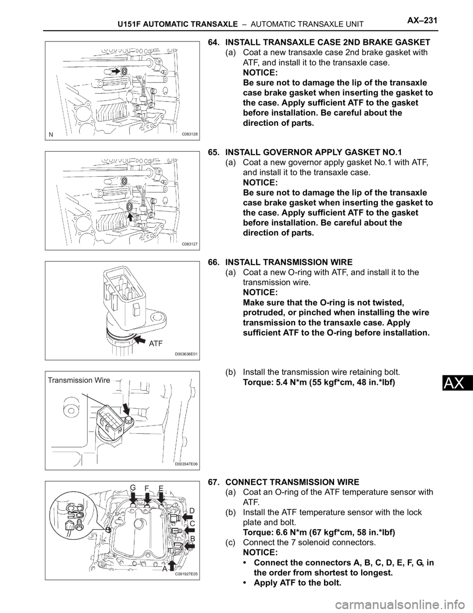
66. INSTALL TRANSMISSION WIRE
(a) Coat a new O-ring with ATF, and install it to the
transmission wire.
NOTICE:
Make sure that the O-ring is not twisted,
protruded, or pinched when installing the wire
transmission to the transaxle case. Apply
sufficient ATF to the O-ring before installation.
(b) Install the transmission wire retaining bolt.
Torque: 5.4 N*m (55 kgf*cm, 48 in.*lbf)
67. CONNECT TRANSMISSION WIRE
(a) Coat an O-ring of the ATF temperature sensor with
AT F.
(b) Install the ATF temperature sensor with the lock
plate and bolt.
Torque: 6.6 N*m (67 kgf*cm, 58 in.*lbf)
(c) Connect the 7 solenoid connectors.
NOTICE:
• Connect the connectors A, B, C, D, E, F, G, in
the order from shortest to longest.
• Apply ATF to the bolt.
C083128
C083127
D003636E01
D003547E06
C091927E05
Page 1924 of 3000
U151F AUTOMATIC TRANSAXLE – AUTOMATIC TRANSAXLE UNITAX–183
AX
9. INSPECT TRANSMISSION OIL CLEANER MAGNET
(a) Remove the magnets and use them to collect any
steel chips. Examine the chips and particles in the
pan and on the magnet to determine what type of
wear has occurred in the transaxle:
Result:
Steel (magnetic):
Wear of the bearing, gear and plate
Brass (non-magnetic):
Wear of the bushing
10. DISCONNECT TRANSMISSION WIRE
(a) Remove the 7 connectors from the shift solenoid
valves.
(b) Remove the bolt, lock plate and temperature
sensor.
11. REMOVE TRANSMISSION WIRE
(a) Remove the bolt and transmission wire from the
transaxle case.
12. REMOVE VALVE BODY OIL STRAINER ASSEMBLY
(a) Remove the 3 bolts and oil strainer.
(b) Remove the O-ring from the oil strainer.
AT00103E03
C091927E02
D003547E05
C091931
C091932E01