Page 2219 of 3000
SP–38SUSPENSION – FRONT STABILIZER BAR (for 4WD)
SP
13. INSTALL FRONT STABILIZER LINK ASSEMBLY LH
HINT:
(See page AH-4)
14. INSTALL FRONT STABILIZER LINK ASSEMBLY RH
HINT:
Install the RH side by the same procedures as the LH
side.
15. INSTALL FRONT WHEELS
16. INSPECT CENTER FRONT WHEEL
17. INSPECT STEERING WHEEL CENTER POINT
18. ADD POWER STEERING FLUID
19. BLEED POWER STEERING FLUID
HINT:
(See page PS-6)
20. CHECK POWER STEERING FLUID LEAKAGE
21. INSPECT AND ADJUST FRONT WHEEL ALIGNMENT
HINT:
(See page SP-4)
Page 2223 of 3000
SP–38SUSPENSION – FRONT STABILIZER BAR (for 4WD)
SP
13. INSTALL FRONT STABILIZER LINK ASSEMBLY LH
HINT:
(See page AH-4)
14. INSTALL FRONT STABILIZER LINK ASSEMBLY RH
HINT:
Install the RH side by the same procedures as the LH
side.
15. INSTALL FRONT WHEELS
16. INSPECT CENTER FRONT WHEEL
17. INSPECT STEERING WHEEL CENTER POINT
18. ADD POWER STEERING FLUID
19. BLEED POWER STEERING FLUID
HINT:
(See page PS-6)
20. CHECK POWER STEERING FLUID LEAKAGE
21. INSPECT AND ADJUST FRONT WHEEL ALIGNMENT
HINT:
(See page SP-4)
Page 2231 of 3000

SP–48SUSPENSION – REAR COIL SPRING
SP
(b) Fully tighten the nut.
Torque: 115 N*m (1,173 kgf*cm, 85 ft.*lbf)
21. FULLY TIGHTEN SHOCK ABSORBER ASSEMBLY
REAR RH
HINT:
Fully tighten the RH side by same procedures as the LH
side.
22. FULLY TIGHTEN REAR AXLE BEAM ASSEMBLY
(a) Stabilize the rear axle beam assembly.
(b) Fully tighten the bolt.
Torque: 135 N*m (1,377 kgf*cm, 100 ft.*lbf)
NOTICE:
• Tighten the bolt and not the nut.
• The vehicle height should be the same as the
height that the shock absorber is fully
tightened.
HINT:
Fully tighten the RH side by same procedures as
the LH side.
23. INSTALL REAR FLOOR NO.2 CROSSMEMBER
BRACE LH
(a) Install the floor No.2 crossmember brace and 2
bolts.
Torque: 28 N*m (286 kgf*cm, 21 ft.*lbf)
24. INSTALL REAR FLOOR NO.2 CROSSMEMBER
BRACE RH
HINT:
Install the RH side by the same procedures as the LH
side.
25. INSTALL FUEL TANK FILLER HOSE COVER
(a) Install the fuel tank filler pipe protector, 2 bolts, 3
screws and 3 nuts.
(b) Install the fuel tank filler hose cover and 3 bolts.
Torque: 5.0 N*m (51 kgf*cm, 44 in.*lbf)
26. INSPECT REAR WHEEL ALIGNMENT
HINT:
(See page SP-9)
27. CHECK ABS SPEED SENSOR SIGNAL
(a) ABS WITH EBD SYSTEM (See page BC-2)
(b) ABS WITH EBD & BA & TRAC & VSC SYSTEM
(See page BC-68)
C088671
G025783
Page 2242 of 3000
SP–54SUSPENSION – REAR SHOCK ABSORBER
SP
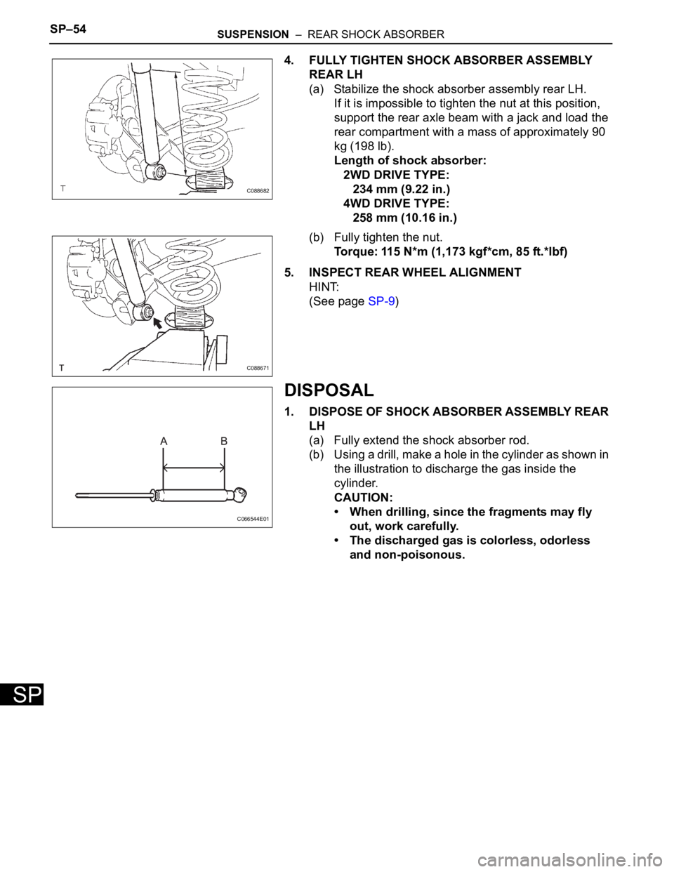
4. FULLY TIGHTEN SHOCK ABSORBER ASSEMBLY
REAR LH
(a) Stabilize the shock absorber assembly rear LH.
If it is impossible to tighten the nut at this position,
support the rear axle beam with a jack and load the
rear compartment with a mass of approximately 90
kg (198 lb).
Length of shock absorber:
2WD DRIVE TYPE:
234 mm (9.22 in.)
4WD DRIVE TYPE:
258 mm (10.16 in.)
(b) Fully tighten the nut.
Torque: 115 N*m (1,173 kgf*cm, 85 ft.*lbf)
5. INSPECT REAR WHEEL ALIGNMENT
HINT:
(See page SP-9)
DISPOSAL
1. DISPOSE OF SHOCK ABSORBER ASSEMBLY REAR
LH
(a) Fully extend the shock absorber rod.
(b) Using a drill, make a hole in the cylinder as shown in
the illustration to discharge the gas inside the
cylinder.
CAUTION:
• When drilling, since the fragments may fly
out, work carefully.
• The discharged gas is colorless, odorless
and non-poisonous.
C088682
C088671
C066544E01
Page 2247 of 3000
SUSPENSION – REAR AXLE BEAMSP–65
SP
45. INSTALL FUEL TANK FILLER HOSE COVER
HINT:
(See page SP-38)
46. INSPECT REAR WHEEL ALIGNMENT
HINT:
(See page SP-9)
47. CHECK ABS SPEED SENSOR SIGNAL
(a) ABS WITH EBD SYSTEM (See page BC-2)
(b) ABS WITH EBD & BA & TRAC & VSC SYSTEM
(See page BC-68)
Page 2453 of 3000
BRAKE CONTROL – VEHICLE STABILITY CONTROL SYSTEMBC–91
BC
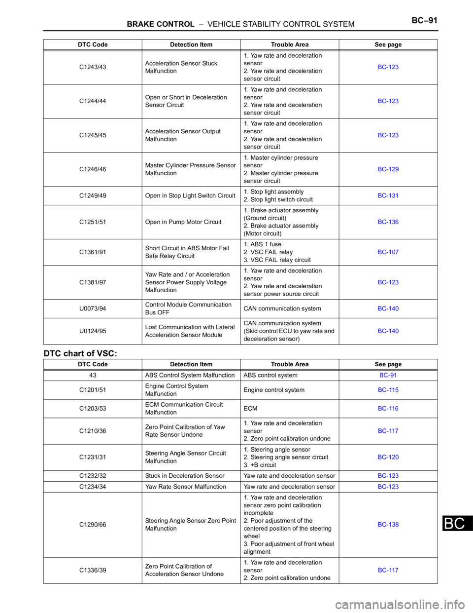
DTC chart of VSC:
C1243/43Acceleration Sensor Stuck
Malfunction1. Yaw rate and deceleration
sensor
2. Yaw rate and deceleration
sensor circuitBC-123
C1244/44Open or Short in Deceleration
Sensor Circuit1. Yaw rate and deceleration
sensor
2. Yaw rate and deceleration
sensor circuitBC-123
C1245/45Acceleration Sensor Output
Malfunction1. Yaw rate and deceleration
sensor
2. Yaw rate and deceleration
sensor circuitBC-123
C1246/46Master Cylinder Pressure Sensor
Malfunction1. Master cylinder pressure
sensor
2. Master cylinder pressure
sensor circuitBC-129
C1249/49 Open in Stop Light Switch Circuit1. Stop light assembly
2. Stop light switch circuitBC-131
C1251/51 Open in Pump Motor Circuit1. Brake actuator assembly
(Ground circuit)
2. Brake actuator assembly
(Motor circuit)BC-136
C1361/91Short Circuit in ABS Motor Fail
Safe Relay Circuit1. ABS 1 fuse
2. VSC FAIL relay
3. VSC FAIL relay circuitBC-107
C1381/97Yaw Rate and / or Acceleration
Sensor Power Supply Voltage
Malfunction1. Yaw rate and deceleration
sensor
2. Yaw rate and deceleration
sensor power source circuitBC-123
U0073/94Control Module Communication
Bus OFFCAN communication systemBC-140
U0124/95Lost Communication with Lateral
Acceleration Sensor ModuleCAN communication system
(Skid control ECU to yaw rate and
deceleration sensor)BC-140
DTC Code Detection Item Trouble Area See page
43 ABS Control System Malfunction ABS control systemBC-91
C1201/51Engine Control System
MalfunctionEngine control systemBC-115
C1203/53ECM Communication Circuit
MalfunctionECMBC-116
C1210/36Zero Point Calibration of Yaw
Rate Sensor Undone1. Yaw rate and deceleration
sensor
2. Zero point calibration undoneBC-117
C1231/31Steering Angle Sensor Circuit
Malfunction1. Steering angle sensor
2. Steering angle sensor circuit
3. +B circuitBC-120
C1232/32 Stuck in Deceleration Sensor Yaw rate and deceleration sensorBC-123
C1234/34 Yaw Rate Sensor Malfunction Yaw rate and deceleration sensorBC-123
C1290/66Steering Angle Sensor Zero Point
Malfunction1. Yaw rate and deceleration
sensor zero point calibration
incomplete
2. Poor adjustment of the
centered position of the steering
wheel
3. Poor adjustment of front wheel
alignmentBC-138
C1336/39Zero Point Calibration of
Acceleration Sensor Undone1. Yaw rate and deceleration
sensor
2. Zero point calibration undoneBC-117 DTC Code Detection Item Trouble Area See page
Page 2502 of 3000
BC–140BRAKE CONTROL – VEHICLE STABILITY CONTROL SYSTEM
BC
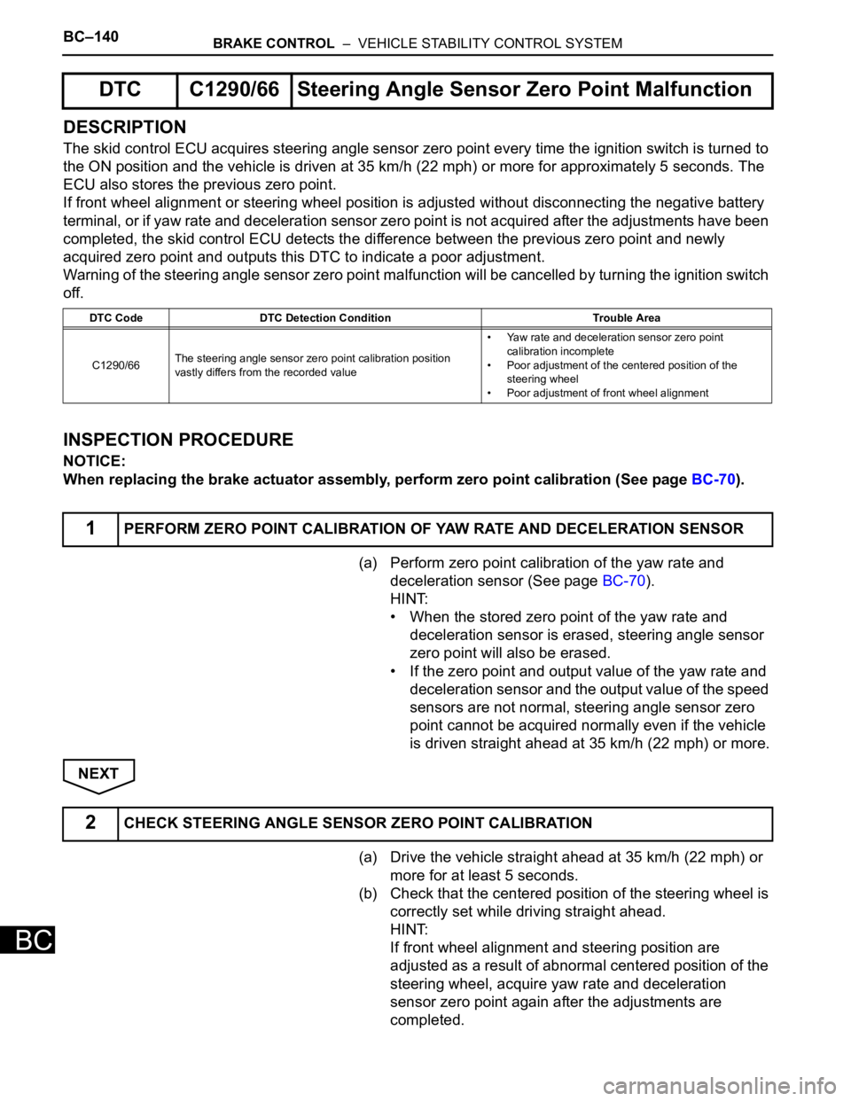
DESCRIPTION
The skid control ECU acquires steering angle sensor zero point every time the ignition switch is turned to
the ON position and the vehicle is driven at 35 km/h (22 mph) or more for approximately 5 seconds. The
ECU also stores the previous zero point.
If front wheel alignment or steering wheel position is adjusted without disconnecting the negative battery
terminal, or if yaw rate and deceleration sensor zero point is not acquired after the adjustments have been
completed, the skid control ECU detects the difference between the previous zero point and newly
acquired zero point and outputs this DTC to indicate a poor adjustment.
Warning of the steering angle sensor zero point malfunction will be cancelled by turning the ignition switch
off.
INSPECTION PROCEDURE
NOTICE:
When replacing the brake actuator assembly, perform zero point calibration (See page BC-70).
(a) Perform zero point calibration of the yaw rate and
deceleration sensor (See page BC-70).
HINT:
• When the stored zero point of the yaw rate and
deceleration sensor is erased, steering angle sensor
zero point will also be erased.
• If the zero point and output value of the yaw rate and
deceleration sensor and the output value of the speed
sensors are not normal, steering angle sensor zero
point cannot be acquired normally even if the vehicle
is driven straight ahead at 35 km/h (22 mph) or more.
NEXT
(a) Drive the vehicle straight ahead at 35 km/h (22 mph) or
more for at least 5 seconds.
(b) Check that the centered position of the steering wheel is
correctly set while driving straight ahead.
HINT:
If front wheel alignment and steering position are
adjusted as a result of abnormal centered position of the
steering wheel, acquire yaw rate and deceleration
sensor zero point again after the adjustments are
completed.
DTC C1290/66 Steering Angle Sensor Zero Point Malfunction
DTC Code DTC Detection Condition Trouble Area
C1290/66The steering angle sensor zero point calibration position
vastly differs from the recorded value• Yaw rate and deceleration sensor zero point
calibration incomplete
• Poor adjustment of the centered position of the
steering wheel
• Poor adjustment of front wheel alignment
1PERFORM ZERO POINT CALIBRATION OF YAW RATE AND DECELERATION SENSOR
2CHECK STEERING ANGLE SENSOR ZERO POINT CALIBRATION
Page 2503 of 3000
BRAKE CONTROL – VEHICLE STABILITY CONTROL SYSTEMBC–141
BC
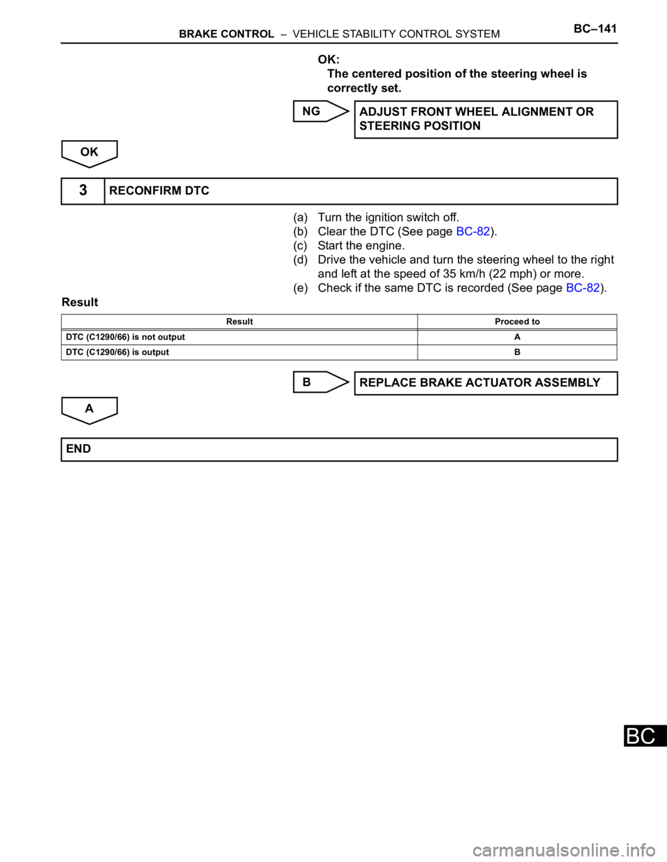
OK:
The centered position of the steering wheel is
correctly set.
NG
OK
(a) Turn the ignition switch off.
(b) Clear the DTC (See page BC-82).
(c) Start the engine.
(d) Drive the vehicle and turn the steering wheel to the right
and left at the speed of 35 km/h (22 mph) or more.
(e) Check if the same DTC is recorded (See page BC-82).
Result
B
AADJUST FRONT WHEEL ALIGNMENT OR
STEERING POSITION
3RECONFIRM DTC
Result Proceed to
DTC (C1290/66) is not outputA
DTC (C1290/66) is outputB
REPLACE BRAKE ACTUATOR ASSEMBLY
END