Page 2212 of 3000
SUSPENSION – FRONT STABILIZER BAR (for 4WD)SP–35
SP
REMOVAL
1. REMOVE FRONT WHEELS
2. REMOVE FRONT STABILIZER LINK ASSEMBLY LH
HINT:
(See page SP-26)
3. REMOVE FRONT STABILIZER LINK ASSEMBLY RH
HINT:
Remove the RH side by the same procedures as the LH
side.
4. REMOVE CENTER EXHAUST PIPE ASSEMBLY
HINT:
(See page EX-8)
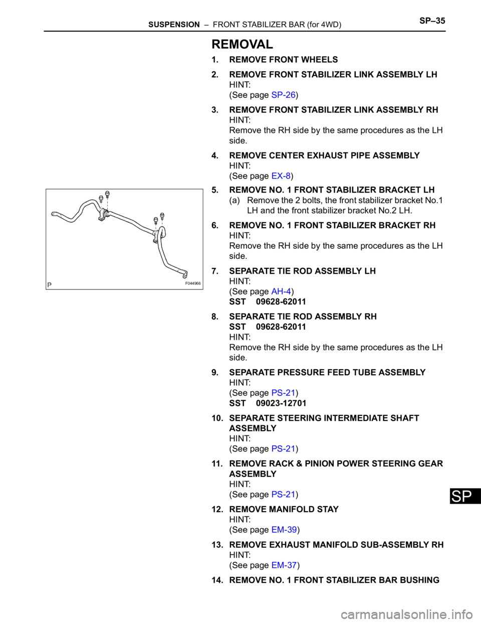
5. REMOVE NO. 1 FRONT STABILIZER BRACKET LH
(a) Remove the 2 bolts, the front stabilizer bracket No.1
LH and the front stabilizer bracket No.2 LH.
6. REMOVE NO. 1 FRONT STABILIZER BRACKET RH
HINT:
Remove the RH side by the same procedures as the LH
side.
7. SEPARATE TIE ROD ASSEMBLY LH
HINT:
(See page AH-4)
SST 09628-62011
8. SEPARATE TIE ROD ASSEMBLY RH
SST 09628-62011
HINT:
Remove the RH side by the same procedures as the LH
side.
9. SEPARATE PRESSURE FEED TUBE ASSEMBLY
HINT:
(See page PS-21)
SST 09023-12701
10. SEPARATE STEERING INTERMEDIATE SHAFT
ASSEMBLY
HINT:
(See page PS-21)
11. REMOVE RACK & PINION POWER STEERING GEAR
ASSEMBLY
HINT:
(See page PS-21)
12. REMOVE MANIFOLD STAY
HINT:
(See page EM-39)
13. REMOVE EXHAUST MANIFOLD SUB-ASSEMBLY RH
HINT:
(See page EM-37)
14. REMOVE NO. 1 FRONT STABILIZER BAR BUSHING
F044966
Page 2216 of 3000
SP–28SUSPENSION – FRONT STABILIZER BAR (for 2WD)
SP
REMOVAL
1. REMOVE FRONT WHEELS
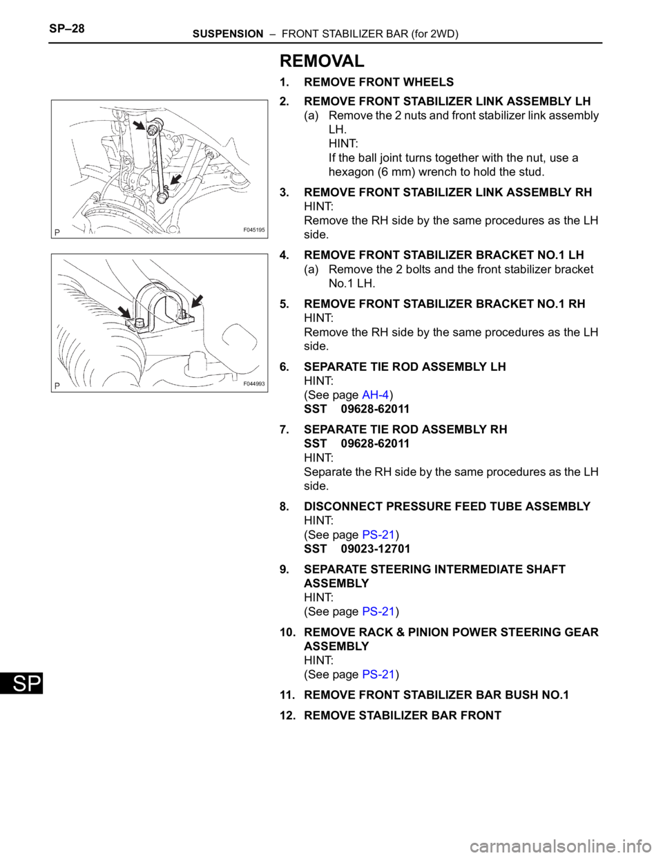
2. REMOVE FRONT STABILIZER LINK ASSEMBLY LH
(a) Remove the 2 nuts and front stabilizer link assembly
LH.
HINT:
If the ball joint turns together with the nut, use a
hexagon (6 mm) wrench to hold the stud.
3. REMOVE FRONT STABILIZER LINK ASSEMBLY RH
HINT:
Remove the RH side by the same procedures as the LH
side.
4. REMOVE FRONT STABILIZER BRACKET NO.1 LH
(a) Remove the 2 bolts and the front stabilizer bracket
No.1 LH.
5. REMOVE FRONT STABILIZER BRACKET NO.1 RH
HINT:
Remove the RH side by the same procedures as the LH
side.
6. SEPARATE TIE ROD ASSEMBLY LH
HINT:
(See page AH-4)
SST 09628-62011
7. SEPARATE TIE ROD ASSEMBLY RH
SST 09628-62011
HINT:
Separate the RH side by the same procedures as the LH
side.
8. DISCONNECT PRESSURE FEED TUBE ASSEMBLY
HINT:
(See page PS-21)
SST 09023-12701
9. SEPARATE STEERING INTERMEDIATE SHAFT
ASSEMBLY
HINT:
(See page PS-21)
10. REMOVE RACK & PINION POWER STEERING GEAR
ASSEMBLY
HINT:
(See page PS-21)
11. REMOVE FRONT STABILIZER BAR BUSH NO.1
12. REMOVE STABILIZER BAR FRONT
F045195
F044993
Page 2218 of 3000
SUSPENSION – FRONT STABILIZER BAR (for 4WD)SP–37
SP
INSTALLATION
1. INSTALL FRONT STABILIZER BAR
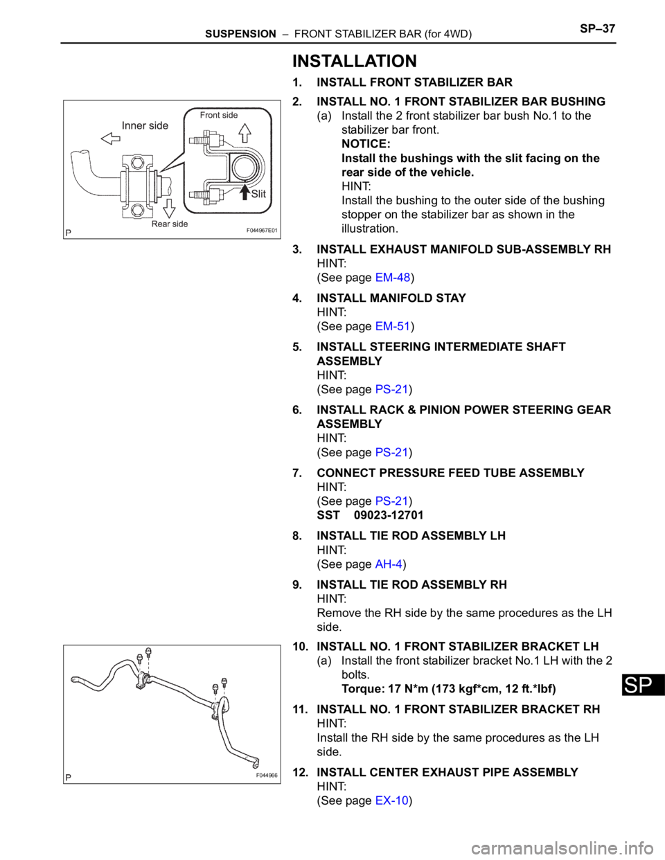
2. INSTALL NO. 1 FRONT STABILIZER BAR BUSHING
(a) Install the 2 front stabilizer bar bush No.1 to the
stabilizer bar front.
NOTICE:
Install the bushings with the slit facing on the
rear side of the vehicle.
HINT:
Install the bushing to the outer side of the bushing
stopper on the stabilizer bar as shown in the
illustration.
3. INSTALL EXHAUST MANIFOLD SUB-ASSEMBLY RH
HINT:
(See page EM-48)
4. INSTALL MANIFOLD STAY
HINT:
(See page EM-51)
5. INSTALL STEERING INTERMEDIATE SHAFT
ASSEMBLY
HINT:
(See page PS-21)
6. INSTALL RACK & PINION POWER STEERING GEAR
ASSEMBLY
HINT:
(See page PS-21)
7. CONNECT PRESSURE FEED TUBE ASSEMBLY
HINT:
(See page PS-21)
SST 09023-12701
8. INSTALL TIE ROD ASSEMBLY LH
HINT:
(See page AH-4)
9. INSTALL TIE ROD ASSEMBLY RH
HINT:
Remove the RH side by the same procedures as the LH
side.
10. INSTALL NO. 1 FRONT STABILIZER BRACKET LH
(a) Install the front stabilizer bracket No.1 LH with the 2
bolts.
Torque: 17 N*m (173 kgf*cm, 12 ft.*lbf)
11. INSTALL NO. 1 FRONT STABILIZER BRACKET RH
HINT:
Install the RH side by the same procedures as the LH
side.
12. INSTALL CENTER EXHAUST PIPE ASSEMBLY
HINT:
(See page EX-10)
F044967E01
F044966
Page 2219 of 3000
SP–38SUSPENSION – FRONT STABILIZER BAR (for 4WD)
SP
13. INSTALL FRONT STABILIZER LINK ASSEMBLY LH
HINT:
(See page AH-4)
14. INSTALL FRONT STABILIZER LINK ASSEMBLY RH
HINT:
Install the RH side by the same procedures as the LH
side.
15. INSTALL FRONT WHEELS
16. INSPECT CENTER FRONT WHEEL
17. INSPECT STEERING WHEEL CENTER POINT
18. ADD POWER STEERING FLUID
19. BLEED POWER STEERING FLUID
HINT:
(See page PS-6)
20. CHECK POWER STEERING FLUID LEAKAGE
21. INSPECT AND ADJUST FRONT WHEEL ALIGNMENT
HINT:
(See page SP-4)
Page 2220 of 3000
SUSPENSION – FRONT STABILIZER BAR (for 4WD)SP–35
SP
REMOVAL
1. REMOVE FRONT WHEELS
2. REMOVE FRONT STABILIZER LINK ASSEMBLY LH
HINT:
(See page SP-26)
3. REMOVE FRONT STABILIZER LINK ASSEMBLY RH
HINT:
Remove the RH side by the same procedures as the LH
side.
4. REMOVE CENTER EXHAUST PIPE ASSEMBLY
HINT:
(See page EX-8)
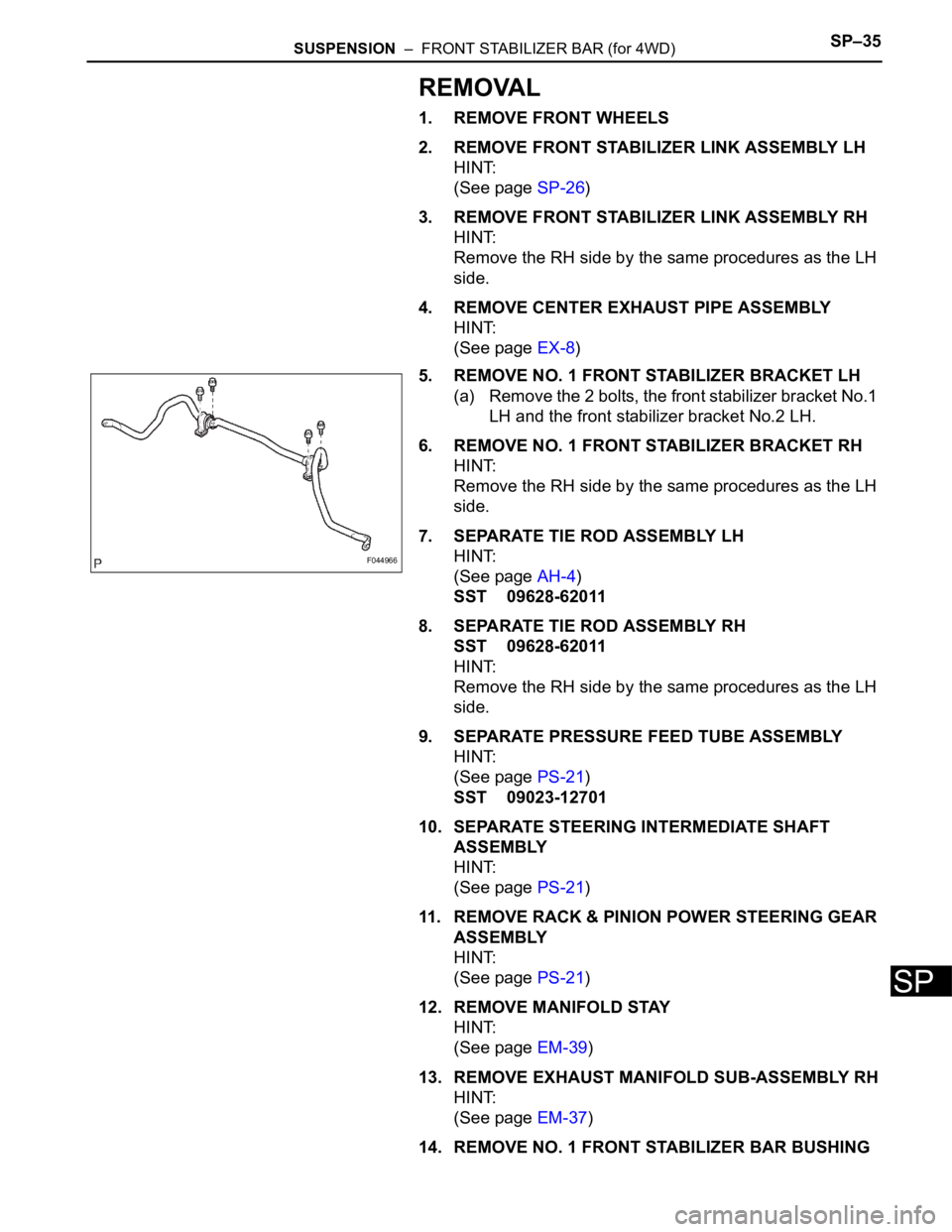
5. REMOVE NO. 1 FRONT STABILIZER BRACKET LH
(a) Remove the 2 bolts, the front stabilizer bracket No.1
LH and the front stabilizer bracket No.2 LH.
6. REMOVE NO. 1 FRONT STABILIZER BRACKET RH
HINT:
Remove the RH side by the same procedures as the LH
side.
7. SEPARATE TIE ROD ASSEMBLY LH
HINT:
(See page AH-4)
SST 09628-62011
8. SEPARATE TIE ROD ASSEMBLY RH
SST 09628-62011
HINT:
Remove the RH side by the same procedures as the LH
side.
9. SEPARATE PRESSURE FEED TUBE ASSEMBLY
HINT:
(See page PS-21)
SST 09023-12701
10. SEPARATE STEERING INTERMEDIATE SHAFT
ASSEMBLY
HINT:
(See page PS-21)
11. REMOVE RACK & PINION POWER STEERING GEAR
ASSEMBLY
HINT:
(See page PS-21)
12. REMOVE MANIFOLD STAY
HINT:
(See page EM-39)
13. REMOVE EXHAUST MANIFOLD SUB-ASSEMBLY RH
HINT:
(See page EM-37)
14. REMOVE NO. 1 FRONT STABILIZER BAR BUSHING
F044966
Page 2222 of 3000
SUSPENSION – FRONT STABILIZER BAR (for 4WD)SP–37
SP
INSTALLATION
1. INSTALL FRONT STABILIZER BAR
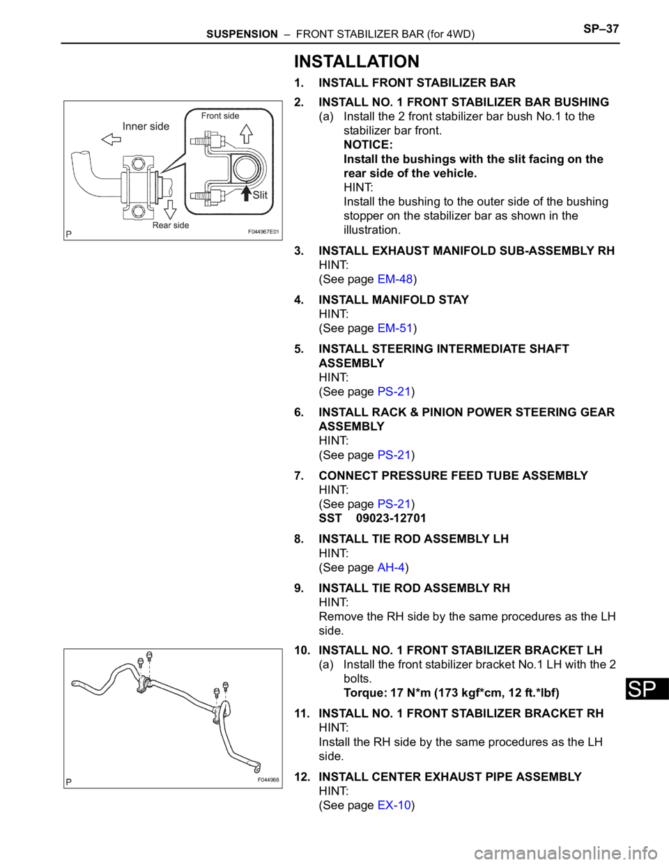
2. INSTALL NO. 1 FRONT STABILIZER BAR BUSHING
(a) Install the 2 front stabilizer bar bush No.1 to the
stabilizer bar front.
NOTICE:
Install the bushings with the slit facing on the
rear side of the vehicle.
HINT:
Install the bushing to the outer side of the bushing
stopper on the stabilizer bar as shown in the
illustration.
3. INSTALL EXHAUST MANIFOLD SUB-ASSEMBLY RH
HINT:
(See page EM-48)
4. INSTALL MANIFOLD STAY
HINT:
(See page EM-51)
5. INSTALL STEERING INTERMEDIATE SHAFT
ASSEMBLY
HINT:
(See page PS-21)
6. INSTALL RACK & PINION POWER STEERING GEAR
ASSEMBLY
HINT:
(See page PS-21)
7. CONNECT PRESSURE FEED TUBE ASSEMBLY
HINT:
(See page PS-21)
SST 09023-12701
8. INSTALL TIE ROD ASSEMBLY LH
HINT:
(See page AH-4)
9. INSTALL TIE ROD ASSEMBLY RH
HINT:
Remove the RH side by the same procedures as the LH
side.
10. INSTALL NO. 1 FRONT STABILIZER BRACKET LH
(a) Install the front stabilizer bracket No.1 LH with the 2
bolts.
Torque: 17 N*m (173 kgf*cm, 12 ft.*lbf)
11. INSTALL NO. 1 FRONT STABILIZER BRACKET RH
HINT:
Install the RH side by the same procedures as the LH
side.
12. INSTALL CENTER EXHAUST PIPE ASSEMBLY
HINT:
(See page EX-10)
F044967E01
F044966
Page 2223 of 3000
SP–38SUSPENSION – FRONT STABILIZER BAR (for 4WD)
SP
13. INSTALL FRONT STABILIZER LINK ASSEMBLY LH
HINT:
(See page AH-4)
14. INSTALL FRONT STABILIZER LINK ASSEMBLY RH
HINT:
Install the RH side by the same procedures as the LH
side.
15. INSTALL FRONT WHEELS
16. INSPECT CENTER FRONT WHEEL
17. INSPECT STEERING WHEEL CENTER POINT
18. ADD POWER STEERING FLUID
19. BLEED POWER STEERING FLUID
HINT:
(See page PS-6)
20. CHECK POWER STEERING FLUID LEAKAGE
21. INSPECT AND ADJUST FRONT WHEEL ALIGNMENT
HINT:
(See page SP-4)
Page 2444 of 3000
BC–80BRAKE CONTROL – VEHICLE STABILITY CONTROL SYSTEM
BC
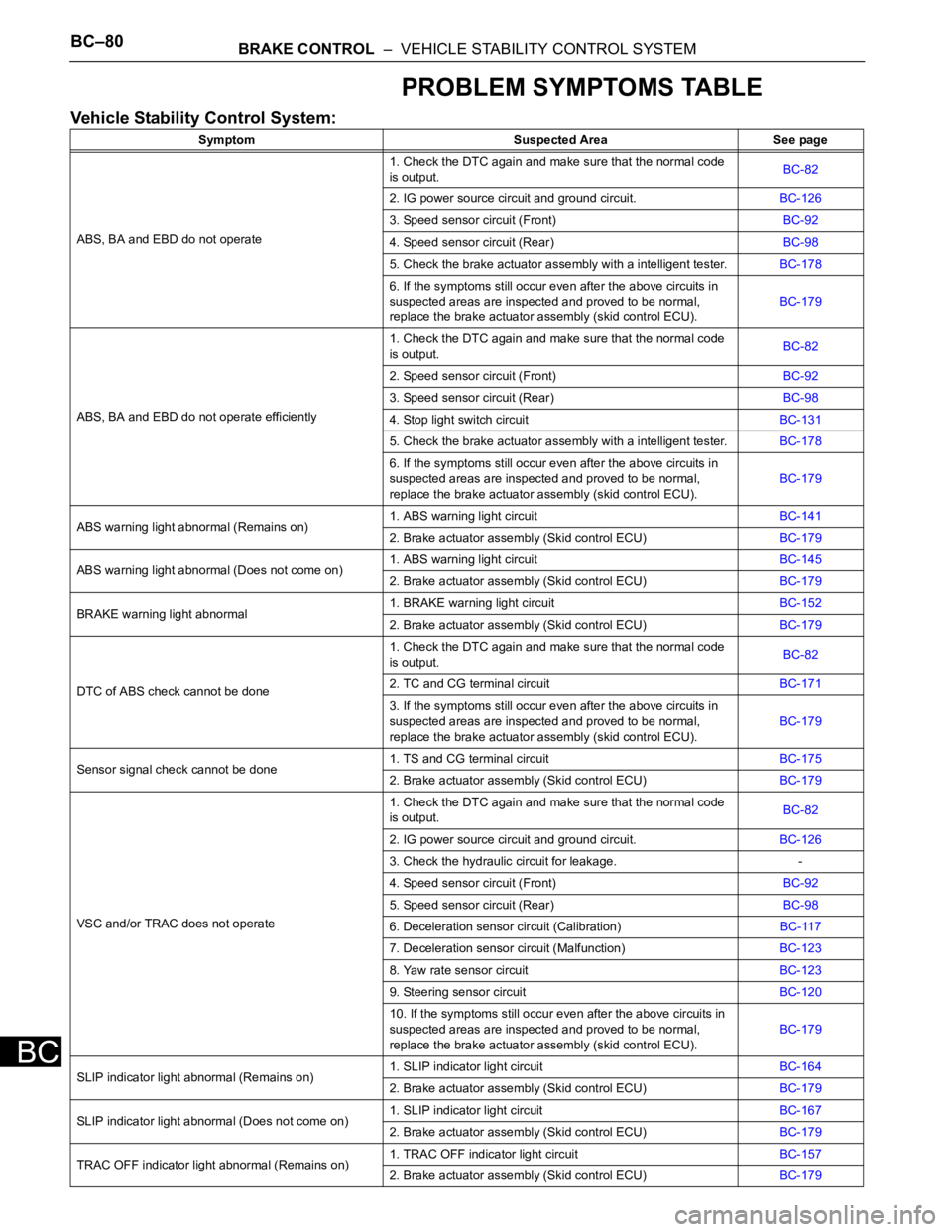
PROBLEM SYMPTOMS TABLE
Vehicle Stability Control System:
Symptom Suspected Area See page
ABS, BA and EBD do not operate1. Check the DTC again and make sure that the normal code
is output.BC-82
2. IG power source circuit and ground circuit.BC-126
3. Speed sensor circuit (Front)BC-92
4. Speed sensor circuit (Rear)BC-98
5. Check the brake actuator assembly with a intelligent tester.BC-178
6. If the symptoms still occur even after the above circuits in
suspected areas are inspected and proved to be normal,
replace the brake actuator assembly (skid control ECU).BC-179
ABS, BA and EBD do not operate efficiently1. Check the DTC again and make sure that the normal code
is output.BC-82
2. Speed sensor circuit (Front)BC-92
3. Speed sensor circuit (Rear)BC-98
4. Stop light switch circuitBC-131
5. Check the brake actuator assembly with a intelligent tester.BC-178
6. If the symptoms still occur even after the above circuits in
suspected areas are inspected and proved to be normal,
replace the brake actuator assembly (skid control ECU).BC-179
ABS warning light abnormal (Remains on)1. ABS warning light circuitBC-141
2. Brake actuator assembly (Skid control ECU)BC-179
ABS warning light abnormal (Does not come on)1. ABS warning light circuitBC-145
2. Brake actuator assembly (Skid control ECU)BC-179
BRAKE warning light abnormal1. BRAKE warning light circuitBC-152
2. Brake actuator assembly (Skid control ECU)BC-179
DTC of ABS check cannot be done1. Check the DTC again and make sure that the normal code
is output.BC-82
2. TC and CG terminal circuitBC-171
3. If the symptoms still occur even after the above circuits in
suspected areas are inspected and proved to be normal,
replace the brake actuator assembly (skid control ECU).BC-179
Sensor signal check cannot be done1. TS and CG terminal circuitBC-175
2. Brake actuator assembly (Skid control ECU)BC-179
VSC and/or TRAC does not operate1. Check the DTC again and make sure that the normal code
is output.BC-82
2. IG power source circuit and ground circuit.BC-126
3. Check the hydraulic circuit for leakage. -
4. Speed sensor circuit (Front)BC-92
5. Speed sensor circuit (Rear)BC-98
6. Deceleration sensor circuit (Calibration)BC-117
7. Deceleration sensor circuit (Malfunction)BC-123
8. Yaw rate sensor circuitBC-123
9. Steering sensor circuitBC-120
10. If the symptoms still occur even after the above circuits in
suspected areas are inspected and proved to be normal,
replace the brake actuator assembly (skid control ECU).BC-179
SLIP indicator light abnormal (Remains on)1. SLIP indicator light circuitBC-164
2. Brake actuator assembly (Skid control ECU)BC-179
SLIP indicator light abnormal (Does not come on)
1. SLIP indicator light circuitBC-167
2. Brake actuator assembly (Skid control ECU)BC-179
TRAC OFF indicator light abnormal (Remains on)1. TRAC OFF indicator light circuitBC-157
2. Brake actuator assembly (Skid control ECU)BC-179