Page 733 of 3000
2GR-FE ENGINE CONTROL SYSTEM – SFI SYSTEMES–447
ES
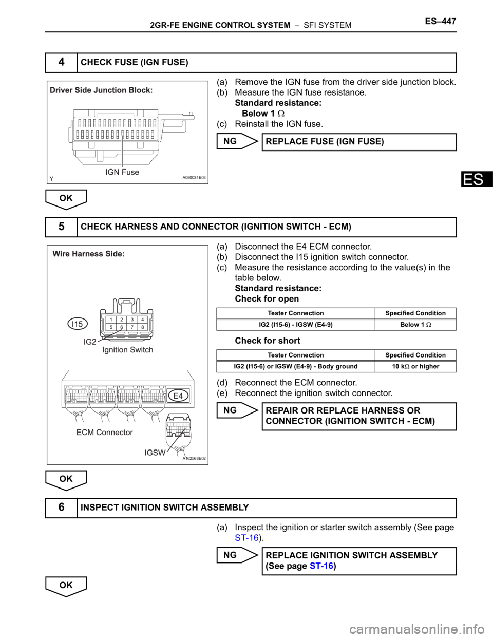
(a) Remove the IGN fuse from the driver side junction block.
(b) Measure the IGN fuse resistance.
Standard resistance:
Below 1
(c) Reinstall the IGN fuse.
NG
OK
(a) Disconnect the E4 ECM connector.
(b) Disconnect the I15 ignition switch connector.
(c) Measure the resistance according to the value(s) in the
table below.
Standard resistance:
Check for open
Check for short
(d) Reconnect the ECM connector.
(e) Reconnect the ignition switch connector.
NG
OK
(a) Inspect the ignition or starter switch assembly (See page
ST-16).
NG
OK
4CHECK FUSE (IGN FUSE)
A080034E03
REPLACE FUSE (IGN FUSE)
5CHECK HARNESS AND CONNECTOR (IGNITION SWITCH - ECM)
A162568E02
Tester Connection Specified Condition
IG2 (I15-6) - IGSW (E4-9) Below 1
Tester Connection Specified Condition
IG2 (I15-6) or IGSW (E4-9) - Body ground 10 k
or higher
REPAIR OR REPLACE HARNESS OR
CONNECTOR (IGNITION SWITCH - ECM)
6INSPECT IGNITION SWITCH ASSEMBLY
REPLACE IGNITION SWITCH ASSEMBLY
(See page ST-16)
Page 734 of 3000
ES–4482GR-FE ENGINE CONTROL SYSTEM – SFI SYSTEM
ES
(a) Remove the AM2 fuse from the engine room junction
block.
(b) Measure the resistance according to the value(s) in the
table below.
Standard resistance:
Below 1
(c) Reinstall the AM2 fuse
NG
OK
(a) Turn the ignition switch to the ON position.
(b) Measure the voltage according to the value(s) in the
table below.
Standard voltage
NG
OK
(a) Remove the EFI No. 1 fuse from the engine room
junction block.
(b) Measure the EFI No. 1 fuse resistance.
Standard resistance:
Below 1
(c) Reinstall the EFI No. 1 fuse.
NG
OK
7CHECK FUSE (AM2 FUSE)
A080011E11
REPLACE FUSE (AM2 FUSE)
REPAIR OR REPLACE HARNESS OR CONNECTOR (IGNITION SWITCH - BATTERY)
8INSPECT ECM (MREL VOLTAGE)
A162489E11
Tester Connection Specified Condition
MREL (E4-8) - E1 (E11-1) 9 to 14 V
REPLACE ECM (See page ES-498)
9CHECK FUSE (EFI NO.1 FUSE)
A080011E09
REPLACE FUSE (EFI NO.1 FUSE)
Page 735 of 3000
2GR-FE ENGINE CONTROL SYSTEM – SFI SYSTEMES–449
ES
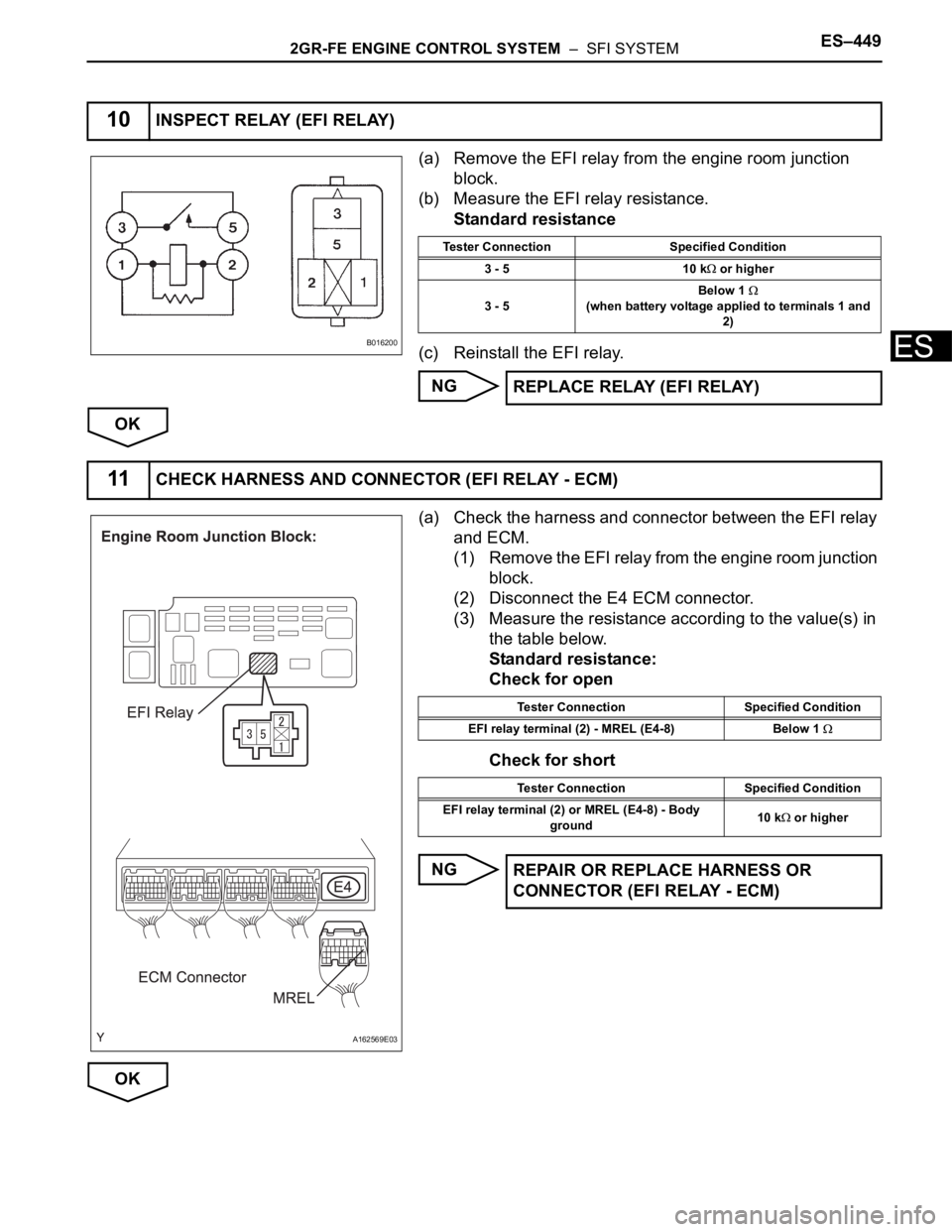
(a) Remove the EFI relay from the engine room junction
block.
(b) Measure the EFI relay resistance.
Standard resistance
(c) Reinstall the EFI relay.
NG
OK
(a) Check the harness and connector between the EFI relay
and ECM.
(1) Remove the EFI relay from the engine room junction
block.
(2) Disconnect the E4 ECM connector.
(3) Measure the resistance according to the value(s) in
the table below.
Standard resistance:
Check for open
Check for short
NG
OK
10INSPECT RELAY (EFI RELAY)
B016200
Tester Connection Specified Condition
3 - 5 10 k
or higher
3 - 5Below 1
(when battery voltage applied to terminals 1 and
2)
REPLACE RELAY (EFI RELAY)
11CHECK HARNESS AND CONNECTOR (EFI RELAY - ECM)
A162569E03
Tester Connection Specified Condition
EFI relay terminal (2) - MREL (E4-8) Below 1
Tester Connection Specified Condition
EFI relay terminal (2) or MREL (E4-8) - Body
ground10 k
or higher
REPAIR OR REPLACE HARNESS OR
CONNECTOR (EFI RELAY - ECM)
Page 736 of 3000
ES–4502GR-FE ENGINE CONTROL SYSTEM – SFI SYSTEM
ES
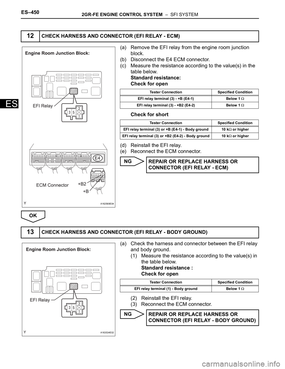
(a) Remove the EFI relay from the engine room junction
block.
(b) Disconnect the E4 ECM connector.
(c) Measure the resistance according to the value(s) in the
table below.
Standard resistance:
Check for open
Check for short
(d) Reinstall the EFI relay.
(e) Reconnect the ECM connector.
NG
OK
(a) Check the harness and connector between the EFI relay
and body ground.
(1) Measure the resistance according to the value(s) in
the table below.
Standard resistance :
Check for open
(2) Reinstall the EFI relay.
(3) Reconnect the ECM connector.
NG
12CHECK HARNESS AND CONNECTOR (EFI RELAY - ECM)
A162569E04
Tester Connection Specified Condition
EFI relay terminal (3) - +B (E4-1) Below 1
EFI relay terminal (3) - +B2 (E4-2) Below 1
Tester Connection Specified Condition
EFI relay terminal (3) or +B (E4-1) - Body ground 10 k
or higher
EFI relay terminal (3) or +B2 (E4-2) - Body ground 10 k
or higher
REPAIR OR REPLACE HARNESS OR
CONNECTOR (EFI RELAY - ECM)
13CHECK HARNESS AND CONNECTOR (EFI RELAY - BODY GROUND)
A163534E02
Tester Connection Specified Condition
EFI relay terminal (1) - Body ground Below 1
REPAIR OR REPLACE HARNESS OR
CONNECTOR (EFI RELAY - BODY GROUND)
Page 741 of 3000
2GR-FE ENGINE CONTROL SYSTEM – SFI SYSTEMES–455
ES
INSPECTION PROCEDURE
(a) Check that the Malfunction Indicator Lamp (MIL) lights
up when turning the ignition switch to the ON position.
OK:
MIL lights up.
OK
NG
(a) Connect the intelligent tester to the DLC3.
(b) Turn the ignition switch to the ON position and turn the
tester on.
(c) Check the communication between the tester and ECM.
Result
A
B
(a) Disconnect the throttle body connector.
(b) Turn the ignition switch to the ON position.
(c) Check the MIL.
Result
(d) Reconnect the throttle body connector.
A
B
(a) Disconnect the accelerator pedal position sensor
connector.
(b) Turn the ignition switch to the ON position.
(c) Check the MIL.
1CHECK MIL
GO TO MIL CIRCUIT (See page ES-478)
2CHECK CONNECTION BETWEEN INTELLIGENT TESTER AND ECM
Result Proceed to
Communication is possible A
Communication is not possible B
GO TO MIL CIRCUIT (See page ES-478)
3CHECK THROTTLE BODY (CHECK MIL ILLUMINATED)
Result Proceed to
MIL illuminates A
MIL does not illuminate B
REPLACE THROTTLE BODY (See page ES-
493)
4CHECK ACCELERATOR PEDAL ROD (CHECK MIL ILLUMINATED)
Page 742 of 3000
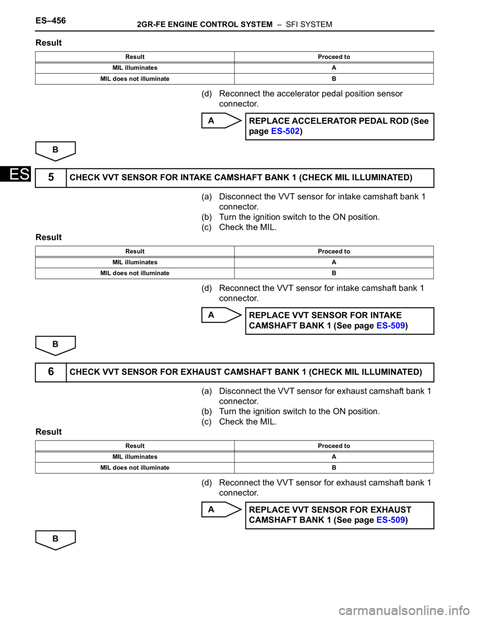
ES–4562GR-FE ENGINE CONTROL SYSTEM – SFI SYSTEM
ES
Result
(d) Reconnect the accelerator pedal position sensor
connector.
A
B
(a) Disconnect the VVT sensor for intake camshaft bank 1
connector.
(b) Turn the ignition switch to the ON position.
(c) Check the MIL.
Result
(d) Reconnect the VVT sensor for intake camshaft bank 1
connector.
A
B
(a) Disconnect the VVT sensor for exhaust camshaft bank 1
connector.
(b) Turn the ignition switch to the ON position.
(c) Check the MIL.
Result
(d) Reconnect the VVT sensor for exhaust camshaft bank 1
connector.
A
B
Result Proceed to
MIL illuminates A
MIL does not illuminate B
REPLACE ACCELERATOR PEDAL ROD (See
page ES-502)
5CHECK VVT SENSOR FOR INTAKE CAMSHAFT BANK 1 (CHECK MIL ILLUMINATED)
Result Proceed to
MIL illuminates A
MIL does not illuminate B
REPLACE VVT SENSOR FOR INTAKE
CAMSHAFT BANK 1 (See page ES-509)
6CHECK VVT SENSOR FOR EXHAUST CAMSHAFT BANK 1 (CHECK MIL ILLUMINAT E D )
Result Proceed to
MIL illuminates A
MIL does not illuminate B
REPLACE VVT SENSOR FOR EXHAUST
CAMSHAFT BANK 1 (See page ES-509)
Page 743 of 3000
2GR-FE ENGINE CONTROL SYSTEM – SFI SYSTEMES–457
ES
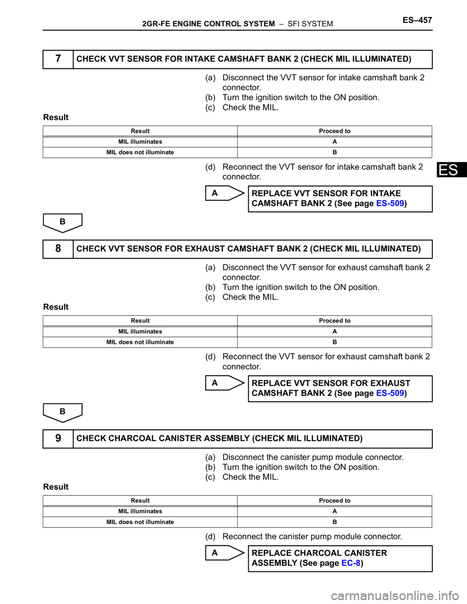
(a) Disconnect the VVT sensor for intake camshaft bank 2
connector.
(b) Turn the ignition switch to the ON position.
(c) Check the MIL.
Result
(d) Reconnect the VVT sensor for intake camshaft bank 2
connector.
A
B
(a) Disconnect the VVT sensor for exhaust camshaft bank 2
connector.
(b) Turn the ignition switch to the ON position.
(c) Check the MIL.
Result
(d) Reconnect the VVT sensor for exhaust camshaft bank 2
connector.
A
B
(a) Disconnect the canister pump module connector.
(b) Turn the ignition switch to the ON position.
(c) Check the MIL.
Result
(d) Reconnect the canister pump module connector.
A
7CHECK VVT SENSOR FOR INTAKE CAMSHAFT BANK 2 (CHECK MIL ILLUMINATED)
Result Proceed to
MIL illuminates A
MIL does not illuminate B
REPLACE VVT SENSOR FOR INTAKE
CAMSHAFT BANK 2 (See page ES-509)
8CHECK VVT SENSOR FOR EXHAUST CAMSHAFT BANK 2 (CHECK MIL ILLUMINAT E D )
Result Proceed to
MIL illuminates A
MIL does not illuminate B
REPLACE VVT SENSOR FOR EXHAUST
CAMSHAFT BANK 2 (See page ES-509)
9CHECK CHARCOAL CANISTER ASSEMBLY (CHECK MIL ILLUMINATED)
Result Proceed to
MIL illuminates A
MIL does not illuminate B
REPLACE CHARCOAL CANISTER
ASSEMBLY (See page EC-8)
Page 744 of 3000
ES–4582GR-FE ENGINE CONTROL SYSTEM – SFI SYSTEM
ES
B
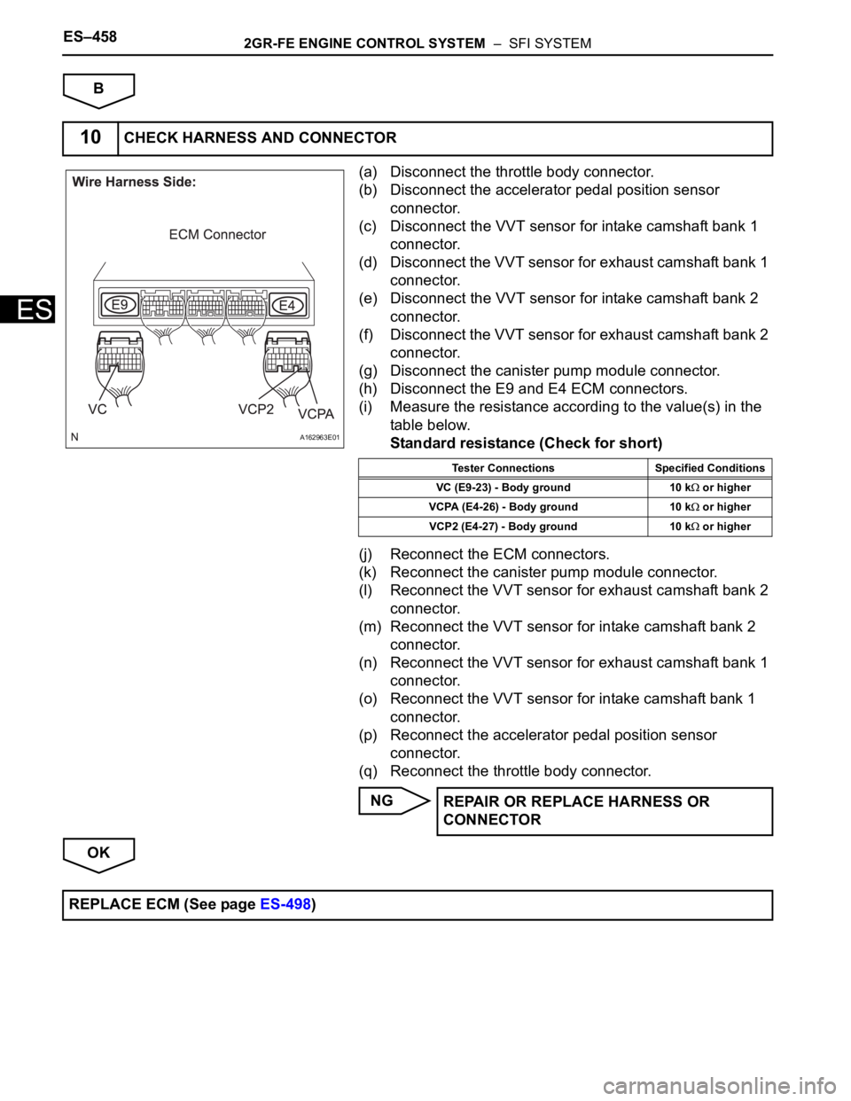
(a) Disconnect the throttle body connector.
(b) Disconnect the accelerator pedal position sensor
connector.
(c) Disconnect the VVT sensor for intake camshaft bank 1
connector.
(d) Disconnect the VVT sensor for exhaust camshaft bank 1
connector.
(e) Disconnect the VVT sensor for intake camshaft bank 2
connector.
(f) Disconnect the VVT sensor for exhaust camshaft bank 2
connector.
(g) Disconnect the canister pump module connector.
(h) Disconnect the E9 and E4 ECM connectors.
(i) Measure the resistance according to the value(s) in the
table below.
Standard resistance (Check for short)
(j) Reconnect the ECM connectors.
(k) Reconnect the canister pump module connector.
(l) Reconnect the VVT sensor for exhaust camshaft bank 2
connector.
(m) Reconnect the VVT sensor for intake camshaft bank 2
connector.
(n) Reconnect the VVT sensor for exhaust camshaft bank 1
connector.
(o) Reconnect the VVT sensor for intake camshaft bank 1
connector.
(p) Reconnect the accelerator pedal position sensor
connector.
(q) Reconnect the throttle body connector.
NG
OK
10CHECK HARNESS AND CONNECTOR
A162963E01
Tester Connections Specified Conditions
VC (E9-23) - Body ground 10 k
or higher
VCPA (E4-26) - Body ground 10 k
or higher
VCP2 (E4-27) - Body ground 10 k
or higher
REPAIR OR REPLACE HARNESS OR
CONNECTOR
REPLACE ECM (See page ES-498)