Page 2659 of 3000

PARKING BRAKE – PARKING BRAKE PEDALPB–5
PB
REMOVAL
1. DISCONNECT BATTERY NEGATIVE TERMINAL
2. REMOVE FRONT DOOR SCUFF PLATE LH
3. REMOVE COWL SIDE TRIM BOARD LH
4. REMOVE INSTRUMENT PANEL FINISH PANEL SUB-
ASSEMBLY LOWER LH (See page IP-6)
5. REMOVE REAR DOOR SCUFF PLATE RH
6. REMOVE REAR DOOR SCUFF PLATE LH
7. REMOVE FRONT SEAT ASSEMBLY LH
HINT:
• Manual Seat Type (See page SE-48)
• Power Seat Type (See page SE-58)
• Fold Flat Type (See page SE-40)
8. REMOVE REAR SEAT NO.1 ASSEMBLY
HINT:
• Captain Seat Type (See page SE-68)
• Center Seat Type (See page SE-77)
9. REMOVE REAR FLOOR SEAT LOCK COVER
10. REMOVE REAR FLOOR SEAT LOCK COVER
11. REMOVE PARKING BRAKE CONTROL PEDAL
ASSEMBLY
(a) Remove the 4 nuts and separate the instrument
panel junction block assembly w/ wiring harness
connector from the body.
(b) Disconnect the parking brake switch connector.
(c) Remove the bolt, 2 nuts and parking brake control
pedal assembly.
DISASSEMBLY
1. REMOVE PARKING BRAKE PEDAL BRACKET
PROTECTOR
(a) Using a flat-head screwdriver, disengage the 2
claws on the parking brake pedal bracket protector.
F045025
F045029
Page 2759 of 3000
AC–40AIR CONDITIONING – AIR CONDITIONING SYSTEM (for Automatic Air Conditioning Sys-
tem)
AC
DESCRIPTION
This sensor detects the rear cabin temperature that is used as the basis for temperature control and
sends a signal to the A/C amplifier.
WIRING DIAGRAM
INSPECTION PROCEDURE
(a) Connect the intelligent tester to the DLC3.
(b) Turn the ignition switch to the ON position and turn the
intelligent tester main switch on.
DTC B1419/19 Rear Room Temperature Sensor Circuit
DTC No. DTC Detection Condition Trouble Area
B1419/19 Rear room temperature sensor circuit (Open or short)• Rear A/C room temperature sensor
• Harness or connector between rear A/C room
temperature sensor and A/C amplifier
• A/C amplifier
1READ VALUE OF INTELLIGENT TESTER
I008282E20
Page 2772 of 3000
AC–26AIR CONDITIONING – AIR CONDITIONING SYSTEM (for Automatic Air Conditioning Sys-
tem)
AC
DESCRIPTION
This sensor detects the cabin temperature that is used as the basis for temperature control and sends a
signal to the A/C amplifier.
WIRING DIAGRAM
INSPECTION PROCEDURE
(a) Connect the intelligent tester to the DLC3.
(b) Turn the ignition switch to the ON position and turn the
intelligent tester main switch on.
DTC B1411/11 Room Temperature Sensor Circuit
DTC No. DTC Detection Condition Trouble Area
B1411/11 Room temperature sensor circuit (Open or short)• A/C room temperature sensor
• Harness or connector between A/C room
temperature sensor and A/C amplifier
• A/C amplifier
1READ VALUE OF INTELLIGENT TESTER
I008282E16
Page 2775 of 3000

AIR CONDITIONING – AIR CONDITIONING SYSTEM (for Automatic Air Conditioning Sys-
tem)AC–29
AC
DESCRIPTION
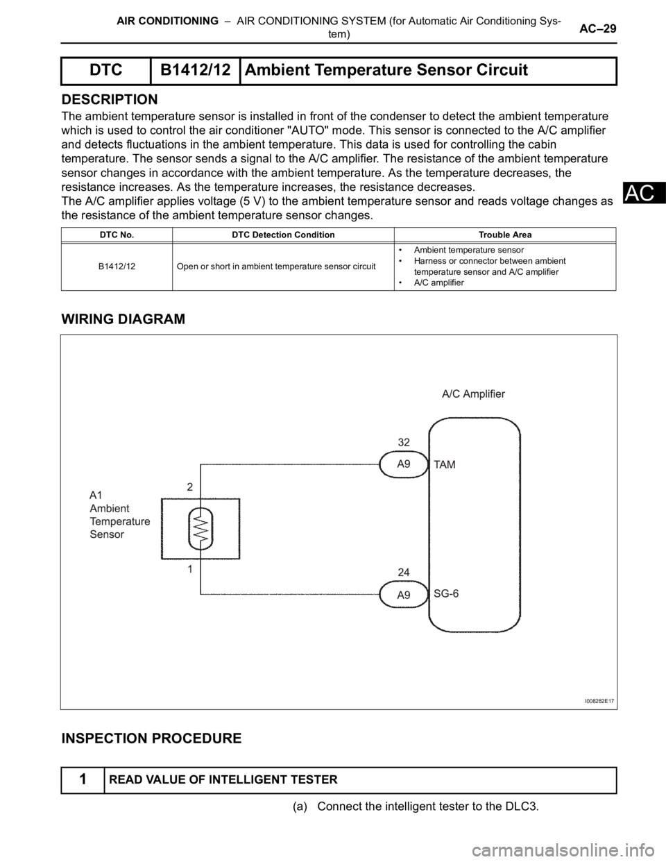
The ambient temperature sensor is installed in front of the condenser to detect the ambient temperature
which is used to control the air conditioner "AUTO" mode. This sensor is connected to the A/C amplifier
and detects fluctuations in the ambient temperature. This data is used for controlling the cabin
temperature. The sensor sends a signal to the A/C amplifier. The resistance of the ambient temperature
sensor changes in accordance with the ambient temperature. As the temperature decreases, the
resistance increases. As the temperature increases, the resistance decreases.
The A/C amplifier applies voltage (5 V) to the ambient temperature sensor and reads voltage changes as
the resistance of the ambient temperature sensor changes.
WIRING DIAGRAM
INSPECTION PROCEDURE
(a) Connect the intelligent tester to the DLC3.
DTC B1412/12 Ambient Temperature Sensor Circuit
DTC No. DTC Detection Condition Trouble Area
B1412/12 Open or short in ambient temperature sensor circuit• Ambient temperature sensor
• Harness or connector between ambient
temperature sensor and A/C amplifier
• A/C amplifier
1READ VALUE OF INTELLIGENT TESTER
I008282E17
Page 2779 of 3000

AIR CONDITIONING – AIR CONDITIONING SYSTEM (for Automatic Air Conditioning Sys-
tem)AC–33
AC
DESCRIPTION
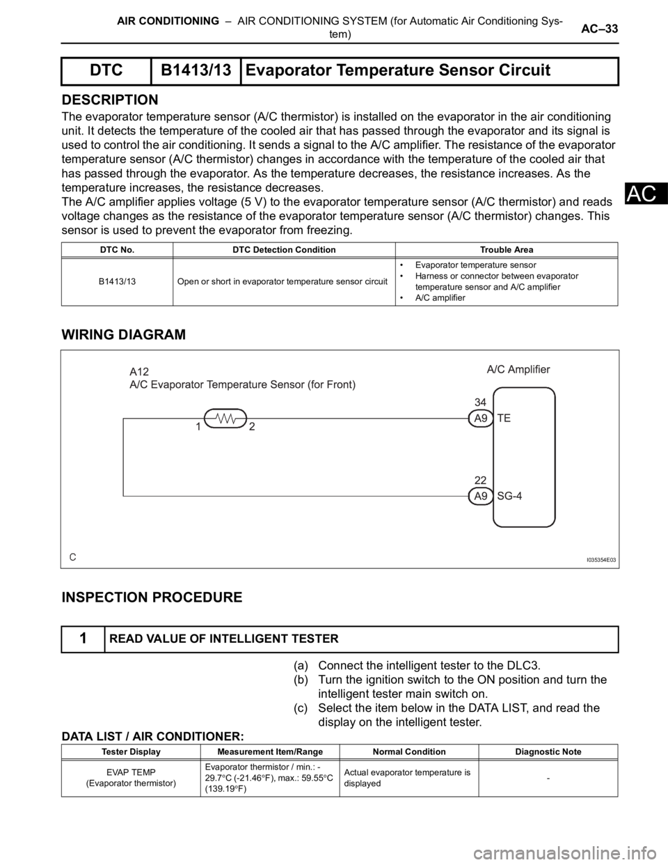
The evaporator temperature sensor (A/C thermistor) is installed on the evaporator in the air conditioning
unit. It detects the temperature of the cooled air that has passed through the evaporator and its signal is
used to control the air conditioning. It sends a signal to the A/C amplifier. The resistance of the evaporator
temperature sensor (A/C thermistor) changes in accordance with the temperature of the cooled air that
has passed through the evaporator. As the temperature decreases, the resistance increases. As the
temperature increases, the resistance decreases.
The A/C amplifier applies voltage (5 V) to the evaporator temperature sensor (A/C thermistor) and reads
voltage changes as the resistance of the evaporator temperature sensor (A/C thermistor) changes. This
sensor is used to prevent the evaporator from freezing.
WIRING DIAGRAM
INSPECTION PROCEDURE
(a) Connect the intelligent tester to the DLC3.
(b) Turn the ignition switch to the ON position and turn the
intelligent tester main switch on.
(c) Select the item below in the DATA LIST, and read the
display on the intelligent tester.
DATA LIST / AIR CONDITIONER:
DTC B1413/13 Evaporator Temperature Sensor Circuit
DTC No. DTC Detection Condition Trouble Area
B1413/13 Open or short in evaporator temperature sensor circuit• Evaporator temperature sensor
• Harness or connector between evaporator
temperature sensor and A/C amplifier
• A/C amplifier
1READ VALUE OF INTELLIGENT TESTER
I035354E03
Tester Display Measurement Item/Range Normal Condition Diagnostic Note
EVAP TEMP
(Evaporator thermistor)Evaporator thermistor / min.: -
29.7
C (-21.46F), max.: 59.55C
(139.19F)Actual evaporator temperature is
displayed-
Page 2782 of 3000

AC–36AIR CONDITIONING – AIR CONDITIONING SYSTEM (for Automatic Air Conditioning Sys-
tem)
AC
DESCRIPTION
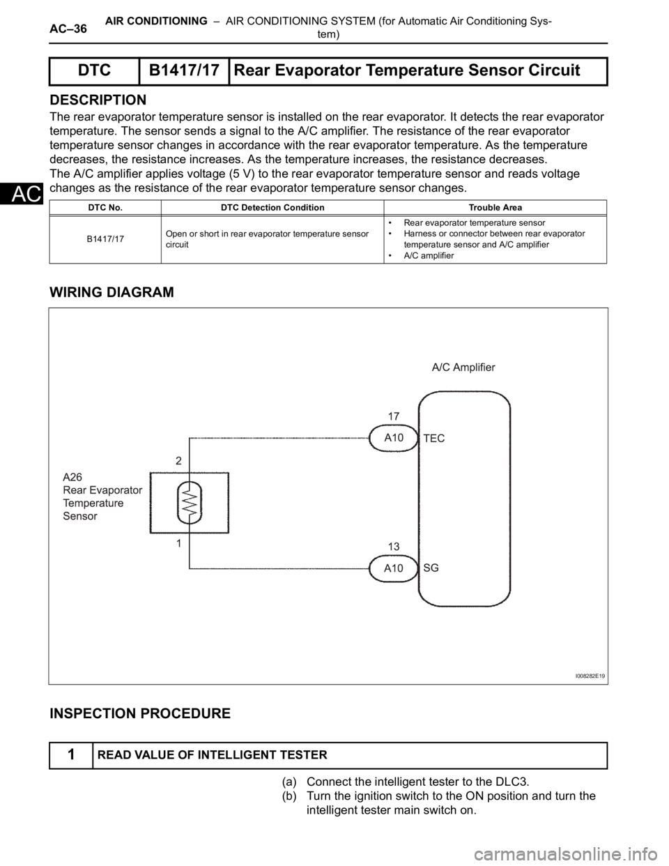
The rear evaporator temperature sensor is installed on the rear evaporator. It detects the rear evaporator
temperature. The sensor sends a signal to the A/C amplifier. The resistance of the rear evaporator
temperature sensor changes in accordance with the rear evaporator temperature. As the temperature
decreases, the resistance increases. As the temperature increases, the resistance decreases.
The A/C amplifier applies voltage (5 V) to the rear evaporator temperature sensor and reads voltage
changes as the resistance of the rear evaporator temperature sensor changes.
WIRING DIAGRAM
INSPECTION PROCEDURE
(a) Connect the intelligent tester to the DLC3.
(b) Turn the ignition switch to the ON position and turn the
intelligent tester main switch on.
DTC B1417/17 Rear Evaporator Temperature Sensor Circuit
DTC No. DTC Detection Condition Trouble Area
B1417/17Open or short in rear evaporator temperature sensor
circuit• Rear evaporator temperature sensor
• Harness or connector between rear evaporator
temperature sensor and A/C amplifier
• A/C amplifier
1READ VALUE OF INTELLIGENT TESTER
I008282E19
Page 2787 of 3000

AC–44AIR CONDITIONING – AIR CONDITIONING SYSTEM (for Automatic Air Conditioning Sys-
tem)
AC
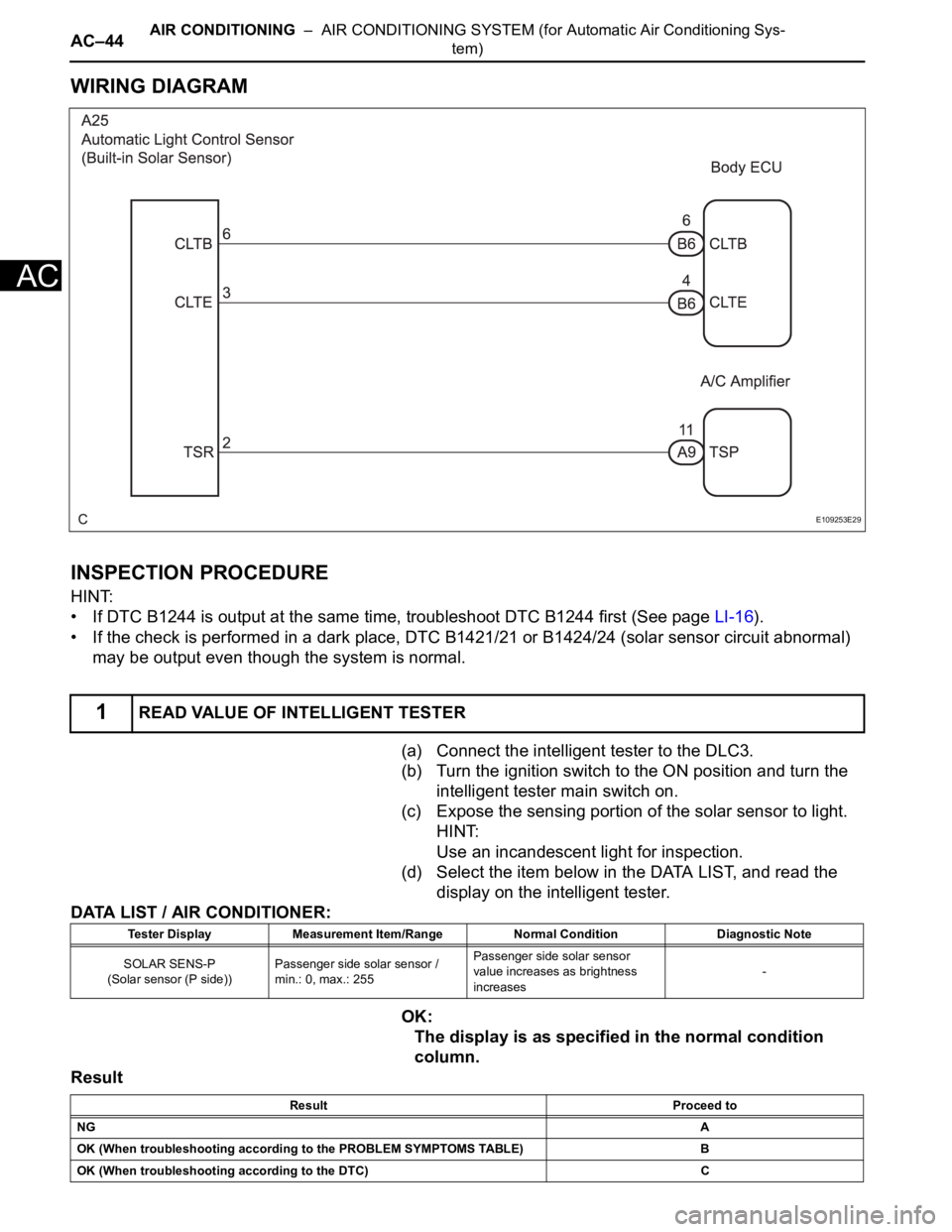
WIRING DIAGRAM
INSPECTION PROCEDURE
HINT:
• If DTC B1244 is output at the same time, troubleshoot DTC B1244 first (See page LI-16).
• If the check is performed in a dark place, DTC B1421/21 or B1424/24 (solar sensor circuit abnormal)
may be output even though the system is normal.
(a) Connect the intelligent tester to the DLC3.
(b) Turn the ignition switch to the ON position and turn the
intelligent tester main switch on.
(c) Expose the sensing portion of the solar sensor to light.
HINT:
Use an incandescent light for inspection.
(d) Select the item below in the DATA LIST, and read the
display on the intelligent tester.
DATA LIST / AIR CONDITIONER:
OK:
The display is as specified in the normal condition
column.
Result
1READ VALUE OF INTELLIGENT TESTER
E109253E29
Tester Display Measurement Item/Range Normal Condition Diagnostic Note
SOLAR SENS-P
(Solar sensor (P side))Passenger side solar sensor /
min.: 0, max.: 255Passenger side solar sensor
value increases as brightness
increases-
Result Proceed to
NGA
OK (When troubleshooting according to the PROBLEM SYMPTOMS TABLE) B
OK (When troubleshooting according to the DTC) C
Page 2791 of 3000
AC–48AIR CONDITIONING – AIR CONDITIONING SYSTEM (for Automatic Air Conditioning Sys-
tem)
AC
SYSTEM DESCRIPTION
The ECM sends an engine speed signal to the A/C amplifier via CAN communication and BEAN
communication.
The A/C amplifier reads the difference between compressor speed and engine speed. When the
difference becomes too large, the A/C amplifier determines that the compressor locks, and turns the
magnetic clutch off.
WIRING DIAGRAM
INSPECTION PROCEDURE
(a) Use the intelligent tester to check if the CAN
communication system is functioning normally.
DTC B1422/22 Compressor Lock Sensor Circuit
DTC No. DTC Detection Condition Trouble Area
B1422/22 Open or short in compressor lock sensor circuit• A/C compressor (A/C lock sensor)
• Compressor drive belt
• Harness or connector between compressor and
magnetic clutch (A/C lock sensor)
• A/C amplifier
• CAN communication system
• Multiplex communication system (BEAN)
1CHECK CAN COMMUNICATION SYSTEM
E147293E02