Page 9 of 59
POWER-ASSISTED STEERING
36B
36B-9V5 MR-372-J84-36B000$198_fra.mif
EPAS
Vdiag no.: 05, 09,
0DPOWER-ASSISTED STEERING
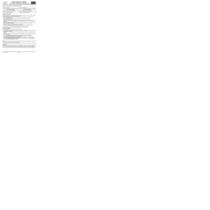
Fault finding – Allocation of computer tracks
Electric Power Assisted Steering computer
8-TRACK CONNECTOR
2-TRACK BLACK CONNECTORTrack Description
1Not used
2Not used
3Not used
4CAN L signal to Instrument panel
5CAN L to UCH
6CAN H signal to Instrument panel
7 CAN H to UCH
8+ 12 V after ignition feed
Track Description
1+ 12 V before ignition feed
2Earth
IMPORTANT
The three white connectors which connect the EPAS computer to the different EPAS sensors must never be
disconnected.
You must not press the connectors more than once when checking that they have been correctly locked into place.
Equally, the three electric motor feed wires must never be unscrewed.
MR-372-J84-36B000$198_fra.mif
Page 10 of 59

POWER-ASSISTED STEERING
Fault finding – Replacement of components
36B
36B-10V5 MR-372-J84-36B000$264_fra.mif
EPAS
Vdiag no.: 05, 09,
0DPOWER-ASSISTED STEERING
Fault finding – Replacement of components
Precautions for use
–The computer, electric motor, upper steering column and angle sensor unit (EPAS) cannot be separated.
A. Replacing the EPAS (computer - upper column assembly):
Before replacing the EPAS, run fault finding on the system: apply the appropriate fault finding procedure.
The EPAS may be replaced only with the consent of the Techline.
When replacing the electric power assisted steering, carry out the following operations in order:
–disconnect the vehicle battery,
–replace the EPAS (see Workshop Repair Manual 370 Mechanics, 36B, Electric power assisted steering),
–reconnect the vehicle battery,
–connect the diagnostic tool, switch on the ignition and establish dialogue with the PAS computer, write the vehicle
VIN by running command VP001,
–configure (see Configuration and programming),
–program the steering wheel angle sensor (only for Vdiag 05 and 09) (see Configuration and programming),
–write the most recent After-Sales operation date by running command VP005,
–switch off the ignition for at least 15 seconds for the configurations to register, without disconnecting the battery,
–switch on the ignition and establish dialogue with the electric power-assisted steering computer,
–turn the steering wheel to full right lock and then to full left lock,
–check that there are no faults and that the variables are correct (notably parameter PR121 Steering wheel angle
for the Vdiag 05 and 09),
–check that the EPAS is working correctly (steering assistance available when the engine is running).
B. Replacing the steering rack (without changing the EPAS):
–disconnect the vehicle battery,
–replace the steering rack (see MR 370 Mechanics, 36B, EPAS),
–reconnect the vehicle battery,
–connect the diagnostic tool, switch on the ignition and establish dialogue with the electric power-assisted steering
computer (EPAS computer),
–program the steering wheel angle sensor (only for Vdiag 05 and 09) (see Configuration and programming),
–turn the steering wheel to full right lock and then to full left lock,
–makesure there a re n o faults a nd check the conformity o f paramete rPR121 Steering wheel angle (Vdiag 05 and 0 9),
–check that the EPAS is working correctly (steering assistance available when the engine is running).
* APV: After-SalesWARNING
You must never leave the ignition switched on or the engine running during a mechanical operation on the electric
power assisted steering or the front axle. To avoid any accident, the battery must be disconnected (to prevent
the danger of accidental triggering of the EPAS motor).
MR-372-J84-36B000$264_fra.mif
Page 11 of 59

POWER-ASSISTED STEERING
36B
36B-11V5 MR-372-J84-36B000$330_fra.mif
EPAS
Vdiag no.: 05, 09,
0DPOWER-ASSISTED STEERING
Fault finding – Configurations and programming
Summary table of configurations and configuration readings
GENERAL INSTRUCTIONS:
After replacing the EPAS computer/steering column unit, configure the computer's assistance strategy and program
the steering wheel angle sensor (only for Vdiag 05 and 09).
The following procedure must be followed in order to carry out the above configuration and programming:
–connect the diagnostic tool,
–switch on the ignition and establish dialogue with the electric power-assisted steering computer,
–select the "Repair mode" menu,
–configure the computer's assistance strategy and program the steering wheel angle sensor (see below),
–exit fault finding mode: stop dialogue with the electric power assisted steering computer without switching off the
CLIP tool,
–switch off the ignition for at least 15 seconds, without disconnecting the battery, for the configuration to be taken
into account by the EPAS computer,
–switch on the ignition again and establish dialogue with the electric power assisted steering computer,
–make sure the configuration readings have been properly registered,
–check that the system is operating correctly (steering assistance available when the engine is running).
A. STEERING WHEEL ANGLE SENSOR PROGRAMMING (only for Vdiag 05 and 09)
PROCEDURE COMPLETE:
(following replacement of the computer/steering column assembly).
Status ET020 Steering wheel angle sensor programming is STATUS 1 (SERVICE indicator light is continuously
lit, see interpretation of status).
–with the ignition on, connect the diagnostic tool and establish dialogue with the electric power assisted steering
computer,
–with the engine stopped or running (to obtain maximum steering assistance), turn the steering wheel to full left lock
and then to full right lock,
–set the vehicle wheels straight ahead, with the steering at the centre point (driving in a straight line),
–run command VP004 Steering wheel angle sensor programming by pressing the CONFIRM button,
–turn the steering wheel to full left lock and then to full right lock,
–Status ET020 Steering wheel angle sensor programming must be STATUS 4 (normal operational status),
–check that parameter PR121 Steering wheel angle varies within the limits indicated in the Conformity check
section and that DF038 Angle sensor is not present. VP001 Enter VIN ID010 VIN code
VP004Steering wheel angle sensor programming
(only for Vdiag 05 and 09)ET020Steering wheel angle sensor programming
(only for Vdiag 05 and 09)
VP005 Enter the APV* operation date ID018 Read last APV* operation date
SC001 Computer calibration ET026 Computer calibration
Note:
To obtain a precise wheels straight ahead position (straight line driving), carry out this operation on a front axle
adjustment bench (especially for vehicles fitted with ESP).
IMPORTANT
If the vehicle is fitted with ESP, establish dialogue with the ABS/ESP computer after the operation; if the function
is available (depending on the computer version) clear the ESP sensor programming using command RZ003.
Make sure there are no ESP faults: carry out the necessary operations by referring to the Fault Finding Manual.
MR-372-J84-36B000$330_fra.mif
Page 12 of 59
 (only for Vdiag 05 and 09)
When starting the engine")
POWER-ASSISTED STEERING
36B
36B-12V5 MR-372-J84-36B000$330_fra.mif
EPAS
Vdiag no.: 05, 09,
0D
STARTING WITH WHEELS TURNED (OUTSIDE RANGE ± 120˚) (only for Vdiag 05 and 09)
When starting the engine with the wheels fully locked (outside range ± 120˚), status ET020 Steering wheel angle
sensor programming is STATUS 3. No fault is indicated by the EPAS or ESP and no indicator light comes on, as
this is a basic operation of the system.
In order for status ET020 to be STATUS 4 turn the wheels so that they are straight (normal operating range).
B. CONFIGURING THE STEERING ASSISTANCE STRATEGY
This configuration enables the computer's assistance strategy to be calibrated depending on the vehicle type, engine
type, gearbox type and tyre sizes.
–with the ignition on, connect the diagnostic tool and establish dialogue with the electric power assisted steering
computer,
–run command SC001 Computer calibration by pressing the CONFIRM button,
–enter the criteria corresponding to the vehicle,
–check, using status ET026 Computer calibration, that the criteria that have been entered correspond
to the vehicle.
Page 13 of 59

POWER-ASSISTED STEERING
36B
36B-13V5 MR-372-J84-36B000$396_fra.mif
EPAS
Vdiag no.: 05, 09,
0DPOWER-ASSISTED STEERING
Fault finding – Fault summary table
Tool
faultDiagnostic tool titleAssociated
DTCCustomer complaints and warning light
coming on
DF001Motor thermal protection5614Steering assistance intermittent reduction.
DF002Computer5608Assistance limited to 30% (with SERVICE
warning light + message) or no assistance
(with STOP warning light + message)
depending on the internal fault code.
DF020Computer supply5601Degraded assistance (no warning light or
message) until a loss of assistance below
9 V or above 17 V with STOP indicator light
+ Message.
DF021Steering wheel angle sensor
programming (only for Vdiag 05 and 09)5612Degraded steering wheel recall (with
SERVICE indicator light + message). ESP
fault, if present.
DF023+ after ignition feed5613Assistance gradually cuts out (within
5 minutes). When the ignition is next
switched on there is no steering
assistance.
DF033Multiplex networkD000Inappropriate level of assistance:
SERVICE indicator light + Message.
DF035Variable power assisted steering motor5606Assistance limited to 30% (with SERVICE
warning light + message) or no steering
assistance (with STOP warning light
+ Message).
DF038Angle sensor (only Vdiag 05 and 09) 5605Steering wheel recall degraded
(no warning light or message). ESP fault,
if present.
DF053Computer configuration5602Defect mode assistance (no message
or warning light).
DF054Torque sensor5604Steering assistance loss or absence with
STOP indicator light + Message.
DF055Computer memory5607Degraded assistance (without warning
light or message) or assistance limited to
10% with SERVICE warning light
+ Message.
Risk of ESP fault.
DF057Vehicle speed multiplex signalD200Inappropriate level of assistance:
SERVICE indicator light + Message.
Note:
Warning light/message
SERVICE + "Check steering" or,
STOP + audible warning + "Faulty steering" or "EPAS fault", depending on the type of instrument panel.
MR-372-J84-36B000$396_fra.mif
Page 14 of 59

POWER-ASSISTED STEERING
Fault finding – Interpretation of faults
36B
36B-14V5 MR-372-J84-36B000$462_fra.mif
EPAS
Vdiag no.: 05, 09,
0DPOWER-ASSISTED STEERING
Fault finding – Interpretation of faults
DF001
PRESENT
OR
STOREDMOTOR THERMAL PROTECTION
NOTESPriority in the event of a number of faults:
Deal with fault DF020 "Computer supply voltage" first, whether it is present
or stored.
Conditions for applying the fault finding procedure to stored faults:
Apply this fault finding procedure even if the fault is stored.
Notes:
This fault does not indicate a system failure, but indicates either overheating of the
Electric Power-Assisted Steering (EPAS) motor (160˚C) or of the computer (100˚C)
during repeated manoeuvres.
This fault can occur following repeated actions on the steering wheel (parking) and
causes a reduction in the steering assistance.
Check the conformity of the battery voltage and carry out fault finding on the charge circuit if necessary.
Remove the underside of the dashboard in order to gain access to the EPAS.
Ensure (carefully) that the EPAS is not still hot.
If the EPAS is still hot, let it cool for an hour before working on it.
Make sure that nothing in the EPAS environment can cause overheating (presence of components under the
dashboard, etc.).
Repair if necessary.
After leaving the EPAS to cool (PR008 Computer temperature and PR009 Steering motor temperature less
than 30˚C), clear the fault, start the engine and check that the EPAS is operating correctly by repeatedly carrying
out parking manoeuvres (turn the wheel slowly from the right-hand to left-hand lock positions).
Check that PR014 Level of assistance available = 100%.
If the fault is present once more or is stored after just a few manoeuvres, contact Techline.
AFTER REPAIRClear the stored faults.
Check that the EPAS is working.
Deal with any other faults.
DAE_V05_DF001/DAE_V09_DF001/DAE_V0D_DF001
MR-372-J84-36B000$462_fra.mif
Page 15 of 59

POWER-ASSISTED STEERING
Fault finding – Interpretation of faults
36B
36B-15V5 MR-372-J84-36B000$462_fra.mif
EPAS
Vdiag no.: 05, 09,
0D
DF002
PRESENT
OR
STOREDCOMPUTER
DEF: Computer fault
NOTESPriority in the event of a number of faults:
In the event of an accumulation of faults, deal with the other present and stored faults
before applying the interpretation for this fault.
Conditions for applying the fault finding procedure to stored faults:
The fault is declared present after having started the engine and turned the steering
wheel from lock to lock.
Notes:
–This fault causes an absence of steering assistance or a loss of steering assistance
and also illuminates the STOP indicator light + Message or assistance is limited to
30% and the SERVICE indicator light + Message come on.
Disconnect the 2 black connectors from the EPAS computer.
Check the condition and conformity of the connectors and their clips.
Check the conformity of the electrical supplies (they must be equal to the battery voltage).
In the event of a fault, check the insulation, continuity and the absence of interference resistance on the
following connections:
8-track connector track 8 + 12 V after ignition
2-track connector track 1 + 12 V before ignition feed
2-track connector track 2 Earth
Repair if necessary.
If the fault is still present, contact the Techline.
AFTER REPAIRClear the stored faults.
Check that the EPAS is working.
Deal with any other faults.
DAE_V05_DF002/DAE_V09_DF002/DAE_V0D_DF002
Page 16 of 59

POWER-ASSISTED STEERING
Fault finding – Interpretation of faults
36B
36B-16V5 MR-372-J84-36B000$462_fra.mif
EPAS
Vdiag no.: 05, 09,
0D
DF020
PRESENT
OR
STOREDCOMPUTER SUPPLY VOLTAGE
1.DEF: Voltage too low
2.DEF: Voltage too high
CO: Open circuit
NOTESConditions for applying the fault finding procedure to stored faults:
The fault is considered present when the engine is running.
Notes:
This fault causes a degraded assistance (no warning light or message) until assistance
is lost (below 9 V or above 17 V) with STOP warning light + Message.
–The computer records an occurrence context (computer operating values frozen
when fault occurs). To view this information, click on the fault description (camera
symbol). Within these values, parameter PR143 Internal fault code gives the fault
finding procedure to apply.
Procedure to apply for internal fault code 135 of the PR143
Check the conditioning and positioning of the EPAS supply fuses:
–Power fuse (80A BP81) in the engine fuse box.
–AP44 after ignition fuse (5A) in the Protection and Switching Unit.
Check the condition and tightness of the battery and alternator terminals, as well as the Protection and Switching
Unit bolt.
Carry out fault finding on the charge circuit.
Repair if necessary.
Disconnect the two black connectors from the EPAS computer.
Check the condition and conformity of the connectors and their clips.
Check the conformity of the electrical supplies (they must be equal to the battery voltage).
In the event of a fault, check the insulation, continuity and the absence of interference resistance on the
following connections:
8-track connector track 8 + 12 V after ignition
2-track connector track 1 + 12 V before ignition feed
2-track connector track 2 Earth
Repair if necessary.
If the fault is still present, contact the Techline.
AFTER REPAIRClear the stored faults.
Check that the EPAS is working.
Deal with any other faults.
DAE_V05_DF020/DAE_V09_DF020/DAE_V0D_DF020