Page 1 of 59

3Chassis
V5 Temp.mif
V5
36B
"The repair procedures given by the manufacturer in this document are based on the
technical specifications current when it was prepared.
The procedures may be modified as a result of changes introduced by the
manufacturer in the production of the various component units and accessories from
which his vehicles are constructed."
V5
All rights reserved by Renault s.a.s.
Edition Anglaise
Copying or translating, in part or in full, of this document or use of the service part
reference numbering system is forbidden without the prior written authority of
Renault s.a.s.
© Renault s.a.s. 2007
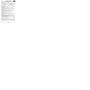
POWER-ASSISTED STEERING
EPASVdiag no.: 05, 09, 0D
Fault finding – Introduction 36B - 2
Fault finding – System operation 36B - 7
Fault finding – Allocation of computer tracks 36B - 9
Fault finding – Replacement of components 36B - 10
Fault finding – Configurations and programming 36B - 11
Fault finding – Fault summary table 36B - 13
Fault finding – Interpretation of faults 36B - 14
Fault finding – Conformity check 36B - 28
Fault finding – Status summary table 36B - 36
Fault finding – Interpretation of statuses 36B - 37
Fault finding – Parameter summary table 36B - 40
Fault finding – Interpretation of parameters 36B - 41
Fault finding – Customer complaints 36B - 47
Fault finding – Fault Finding Chart 36B - 48
Page 2 of 59

POWER-ASSISTED STEERING
Fault finding – Introduction
36B
36B-2V5 MR-372-J84-36B000$066_fra.mif
136B
EPAS
Vdiag no.: 05, 09,
0DPOWER-ASSISTED STEERING
Fault finding – Introduction
1. SCOPE OF THIS DOCUMENT
This document presents the fault finding procedure applicable to all computers with the following specifications:
2. PREREQUISITES FOR FAULT FINDING
Documentation type
Fault finding procedures (this manual):
–Assisted fault finding (integrated into the diagnostic tool), Dialogys.
Wiring Diagrams:
–Visu-Schéma (CD-ROM), paper.
Type of diagnostic tools
–CLIP
Special tooling required
3. REMINDER
Procedure
To run fault finding on the vehicle's computers, switch on the ignition in fault finding mode (forced + after ignition
feed).
Proceed as follows:
–vehicle card in reader,
–press and hold start button (longer than 5 seconds) with start-up conditions not fulfilled,
–connect the diagnostic tool and perform the required operations.
To cut off + after ignition feed, proceed as follows:
–disconnect the diagnostic tool,
–press the Start button twice briefly (less than 3 seconds),
–ensure that the + after ignition feed has been cut off by checking that the computer indicator lights on the instrument
panel have gone out. Vehicle(s): Scenic II
Function concerned: EPASComputer name: Electric power assisted steering
Vdiag no.: 05, 09, 0D
Special tooling required
Multimeter
Elé. 1681Universal bornier
DAE_V05_ PRELI/DAE_V09_ PRELI/DAE_V0D_ PRELI
MR-372-J84-36B000$066_fra.mif
Page 3 of 59

POWER-ASSISTED STEERING
Fault finding – Introduction
36B
36B-3V5 MR-372-J84-36B000$066_fra.mif
EPAS
Vdiag no.: 05, 09,
0D
Faults
Faults are declared present or stored (depending on whether they appeared in a certain context and have
disappeared since, or whether they remain present but are not diagnosed within the current context).
The present or stored status of faults should be taken into consideration when the diagnostic tool is switched on
after the + after ignition feed (without any system components being active).
For a present fault, apply the procedure described in the Interpretation of faults section.
For a stored fault, note the faults displayed and apply the instructions in the Notes section.
If the fault is confirmed when the instructions in the Notes section are applied, the fault is present. Deal with
the fault.
If the fault is not confirmed, check:
–the electrical lines which correspond to the fault,
–the connectors for these lines (for oxidation, bent pins, etc.),
–the resistance of the component detected as defective,
–the condition of the wires (melted or split insulation, wear).
Conformity check
The aim of the conformity check is to check data that does not produce a fault on the diagnostic tool because the
data is inconsistent. Therefore, this stage is used to:
–carry out fault finding on faults that do not have a fault display, and which may correspond to a customer complaint.
–check that the system is operating correctly and that there is no risk of a fault recurring after repairs.
This section gives the fault finding procedures for statuses and parameters and the conditions for checking them.
If a status is not behaving normally or a parameter is outside the permitted tolerance values, consult the
corresponding fault finding page.
Customer complaints - Fault finding chart
If the test with the diagnostic tool is OK but the customer complaint is still present, the fault should be processed by
customer complaints.
A synopsis of the general procedure to follow is provided on the following page in the form of a flow chart.
Page 4 of 59
POWER-ASSISTED STEERING
Fault finding – Introduction
36B-4
36B
V5 MR-372-J84-36B000$066_fra.mif
EPAS
Vdiag no.: 05, 09,
0D
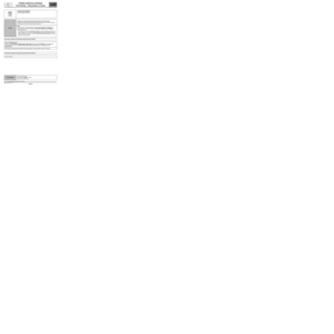
4. FAULT FINDING PROCEDURE
Perform a pre-diagnostic on the
system
Print the system fault finding log
(available on CLIP and in the
Workshop Repair Manual or
Technical Note)
Connect CLIP
no
Dialogue with
computer?
yes
Read the faults
no
Faults present
yes
Deal with present faults
Deal with stored faults
no
The cause is still
presentFault
solved
yes
Refer to ALP No. 1
Conformity check
no
The cause is still
presentFault
solved
Use fault finding charts (ALPs)
no
The cause is still
presentFault
solved
Contact the Techline with the
completed fault finding log
Page 5 of 59

Wiring check
Fault finding problems
Dis")
POWER-ASSISTED STEERING
Fault finding – Introduction
36B
36B-5V5 MR-372-J84-36B000$066_fra.mif
EPAS
Vdiag no.: 05, 09,
0D
FAULT FINDING PROCEDURE (continued)
Wiring check
Fault finding problems
Disconnecting the connectors and/or manipulating the wiring harness may temporarily remove the cause of a fault.
Electrical measurements of voltage, resistance and insulation are generally correct, especially if the fault is not
present when the analysis is made (stored fault).
Visual inspection
Look for damage under the bonnet and in the passenger compartment.
Carefully check the fuses, insulators and wiring harness routing.
Look for signs of oxidation.
Physical inspection
While manipulating the wiring harness, use the diagnostic tool to note any change in fault status from stored
to present.
Make sure that the connectors are properly locked.
Apply light pressure to the connectors.
Twist the wiring harness.
If there is a change in status, try to locate the source of the fault.
Inspection of each component
Disconnect the connectors and check the appearance of the clips and tabs, as well as the crimping (no crimping on
the insulating section).
Make sure that the clips and tabs are properly locked in the sockets.
Check that no clips or tabs have been dislodged during connection.
Check the clip contact pressure using an appropriate model of tab.
Resistance check
Check the continuity of entire lines, then section by section.
Look for a short circuit to earth, to + 12 V or to another wire.
If a fault is detected, repair or replace the wiring harness.
Page 6 of 59

POWER-ASSISTED STEERING
Fault finding – Introduction
36B
36B-6V5 MR-372-J84-36B000$066_fra.mif
EPAS
Vdiag no.: 05, 09,
0D
5. FAULT FINDING LOG
You will always be asked for this log:
–when requesting technical assistance from Techline,
–for approval requests when replacing parts for which approval is mandatory,
–to be attached to monitored parts for which reimbursement is requested. The log is needed for warranty
reimbursement, and enables better analysis of the parts removed.
6. SAFETY INSTRUCTIONS
Safety rules must be observed during any work on a component to prevent any damage or injury:
–check the battery voltage to avoid incorrect operation of computer functions,
–use the proper tools. IMPORTANTIMPORTANT
Any fault on a complex system requires thorough fault finding with the appropriate tools.
The FAULT FINDING LOG, which should be completed during the procedure, enables you to
keep track of the procedure which is carried out. It is an essential document when consulting the
manufacturer.
IT IS THEREFORE ESSENTIAL THAT THE FAULT FINDING LOG IS FILLED OUT EVERY TIME IT IS
REQUESTED BY TECHLINE OR THE WARRANTY RETURNS DEPARTMENT.
Page 7 of 59

POWER-ASSISTED STEERING
Fault finding – System operation
36B
36B-7V5 MR-372-J84-36B000$132_fra.mif
EPAS
Vdiag no.: 05, 09,
0DPOWER-ASSISTED STEERING
Fault finding – System operation
GENERAL OPERATION
On this vehicle, the steering system is power-assisted by an electric motor attached to the steering column.
The action of the driver is relayed by a torque sensor, which measures the force applied to the steering wheel,
and a steering column angle sensor (steering wheel angle sensor only on Vdiag 05 and 09). Assistance is given
by an electric motor which applies more or less torque to the steering column, in one direction or the other.
A computer controls this assistance according to several vehicle environment parameters, including the vehicle
speed.
EPAS ALSO OFFERS THE FOLLOWING:
Active recall:
This function is used to bring the steering wheel back to the straight-ahead position when driving at low speeds but
not when the vehicle is stationary. This function is normal on hydraulic power-assisted steering vehicles or vehicles
without assistance.
This function cannot be deactivated by the diagnostic tool.
For Vdiag 05 and 09 (columns with steering wheel angle sensor): this feature is inactive when the steering wheel
angle is not available (ET020 Programming steering wheel angle sensor for STATUS 1, STATUS 2, STATUS 3).
For Vdiag 0D (columns without steering wheel angle sensor): this feature is always inactive.
Lock torque limit:
This function limits the assistance torque when the steering wheel is held at full lock with considerable effort, when
the vehicle is stationary or travelling at a speed less than 3 mph (5 km/h). The purpose of this function is to limit
overheating of the electric power assisted steering motor.
Note:
When the computer detects a fault, the level of assistance can be modified depending on how serious the fault is.
An incorrect or absent vehicle speed signal results in assistance equal to that provided at 60 mph (100 km/h)
without active recall. The EPAS sends a steering wheel angle signal to the ESP computer (if fitted).
MR-372-J84-36B000$132_fra.mif
Page 8 of 59
POWER-ASSISTED STEERING
Fault finding – System operation
36B
36B-8V5 MR-372-J84-36B000$132_fra.mif
EPAS
Vdiag no.: 05, 09,
0D
SIGNALS RECEIVED AND SENT
Vehicle speed
Power-assisted
steering computerSteering wheel angle (Vdiag
05 and 09)
Engine status Column rotation speed
Power supply (permanent +)Instrument panel indicator
light on
Supply (+ after ignition feed) Diagnostic socket
Earth